1
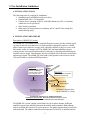
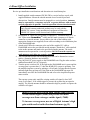
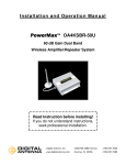
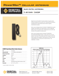
Installation and Operation Manual
PowerMaxTM 4KMR-30U
40dB Gain Dual Band
Wireless Amplifier/Repeater System
Read Instructions before installing!
If you do not understand instructions,
seek professional installation.
D IGITA L
AN TEN N A
>Digital Antenna, Inc.
>5325 NW 108th Avenue
>t 954.747.7022
>www.digitalantenna.com
>Sunrise, FL 33351
>f 954.747.7088
INSTALLATION AND OPERATION MANUAL Model #4KMR-30U
1. Package Contents……………………………………………………………….………3
2. Important Safety Information…………………………………………………………..3
a. Limited Warranty………………………………………………….……....4
b. Limitation on Liability…………………………………………….………4
c. FCC Regulations…………………………………………………………..4
3. Pre-installation Guidelines……………………………………………………………...5
a. Installation Tools…………………………………………………...……..5
b. Installation Procedure………………………………………….……..…...5
c. Electrical Power…………………………………….…………………......6
d. Amplifier/Repeater Status………………………….……………………...7
e. Interior Coverage Problems……..………………………………………...8
f. Coaxial Cable Recommendations…………………………………………9
4. Home/Office Installation……...………………………………………………...…….10
5. Marine Installation………………………………………………………………..…...11
6. RV Installation………………………………………………………………………...12
7. Specifications…………………………………………………………………….……13
8. Antenna & Accessory Options……………………………….………………………..15
9. Technical Support……………………………………………………………………..16
For answers to Frequently Asked Questions visit www.DigitalAntenna.com
2
IMPORTANT
Read instructions completely before attempting install!
1. Package Contents
Part Number
DA4000MR
288-PW
135-RD
DP515
DP255
240-30NM
DH288
Description
Dual Band Wireless Cellular Amplifier/Repeater
Outside omni-directional 9dB gain dual band cell antenna
Inside omni-directional dual band cell antenna with 6’ cable
Microprocessor controlled 12 VDC to 5 VDC power cable
110-240 VAC to 5 VDC power supply
30’ DA240 low loss cable
Stainless steel mounting hardware: qty 2 U-bolts, nuts, washers; qty 4
Phillips head screws
2. Important Safety Information
The 4KMR-30U system complies with all FCC, IC, UL rules, regulations and codes.
Follow all guidelines in the installation and instruction manual and read completely
before beginning the installation procedure. Do not deviate or disregard any of the safety
features included in the manual or with the equipment, nor operate the system in an
unintended manner.
WARNING!
Only Digital Antenna authorized products may be used with the 4KMR30U system. Using unauthorized equipment with the 4KMR-30U system
will harm the system, voids the warranty and can be detected in the event
of a failure.
WARNING!
Do not install antenna near power lines. Contact with any high voltage
power lines could result in shock or loss of life.
WARNING!
Handle all electronic parts with care. Dropping or mishandling the
DA4000MR amplifier/repeater, antennas or power supplies can damage
sensitive RF and electronic components.
DO NOT TURN AMPLIFIER ON
UNTIL ANTENNAS ARE SECURELY
ATTACHED TO AMPLIFIER AND
PROPERLY SEPARATED
3
a. LIMITED WARRANTY
Digital Antenna, Inc. warrants, to the original owner, marine antennas for five (5) years and cellular antennas and
amplifiers for one (1) year that its Products sold hereunder will at the time of shipment be free from defects in material
and workmanship and will conform to Digital Antenna’s applicable specifications or, if appropriate, to Customer’s
specifications previously accepted by Digital Antenna in writing.
If products sold hereunder are not as warranted, Digital Antenna shall, at its option repair or replace the product,
provided proof of purchase and written notice of nonconformance are received by Digital Antenna within five (5) or
one (1) years of date of purchase and provided said nonconforming Products are, with Digital Antenna’s written
authorization, returned in protected shipping containers. Customer is responsible for shipping the product to Digital
Antenna. Digital Antenna will pay for transporting via ground service only the repaired product to Customer. Express
service will incur a fee and must be paid by Customer prior to shipping.
This warranty shall not apply to any Products Digital Antenna determined to have been, by Customer or otherwise,
subjected to mishandling, misuse, neglect, improper testing, repair alteration, damage, assembly or processing that
alters physical or electrical properties.
b. LIMITATION ON LIABILITY
In no event shall Digital Antenna, Inc. Be liable for any direct, indirect, special, punitive, incidental, exemplary or
consequential damages, or any damages whatsoever, even if Digital Antenna, Inc. Has been previously advised of the
possibility of such damages, whether in an action under contract, negligence, or any other theory, arising out of or in
connection with the use, inability to use, or performance of the information, services, products, and materials available
from this manual. These limitations shall apply notwithstanding any failure of essential purpose of any limited remedy.
Because some jurisdictions do not allow limitations on how long an implied warranty lasts, or the exclusion or
limitation of liability for consequential or incidental damages, the above limitations may not apply to you.
c. FCC REGULATIONS
FCC ID: PZODA4000SBR
This equipment has been tested and found to comply with the limits for a class B device, pursuant to Part 15 of the FCC
rules. These limits are designed to provide reasonable protection against harmful interference. This equipment
generates, uses and can radiate radio frequency energy and if not installed and used in accordance with this instruction
manual, may cause harmful interference to radio communications, However, there is no guarantee that interference
will not occur in a particular installation. If this equipment does cause harmful interference to radio or other electronic
reception, which can be determined by turning the equipment off and on, the user is encouraged to try to correct the
interference by one of more of the following measures:
•
•
•
•
•
Reorient or relocate the receiving antenna
Increase the separation between the equipment and receiver
Connect to isolated power with a ground cable going directly to the battery, DC source or house ground
Repositioning of the coaxial cable may also eliminate interference
Consult the dealer or an experienced electronics technician for help.
Warning: Changes or modifications not expressly approved by Digital Antenna, Inc. could void the user's authority to
operate the equipment.
4
3. Pre-Installation Guidelines
a. INSTALLATION TOOLS
The following tools are required for installation:
• Standard wrench and Phillips head screwdriver
• Standard drill with ½” bit (optional)
• Cellular device operating on 800 or 1900 MHz bands (any USA or Canadian
cellular device except Nextel)
• Wire fasteners (optional)
• Multi-meter for testing electrical continuity and AC and DC line voltage (for
troubleshooting only)
b. INSTALLATION PROCEDURE
Description of 4KMR-30U system
The 4KMR-30U Dual Band Wireless Amplifier/Repeater system provides cellular signal
coverage to interior areas that have low signal strength to adequately operate a cellular
phone. In these poor interior coverage areas it becomes difficult to place or receive calls
and usually results in a dropped call. The 4KMR-30U dual band amplifier/repeater
system provides increased reception indoors by filtering, re-directing and amplifying the
available exterior signal. This translates into fewer dropped calls with clearer connections
and stronger signals. The 4KMR-30U dual band system operates with all carriers in the
USA and Canada except Nextel/iDEN providers.
P/N 288-PW
Outside
Antenna
R e qu ir ed
O u ts id e C ell S ig n a l
(-9 0 to -7 0d B m )
R e quir ed
m in. 20' plu s stru ctur e
be tw een a n ten nas
m us t be a ble to m a k e
a nd c om p lete c a lls
P/N 240-30NM
30' Cable
Cell Site
P/N 135-RD
Inside Antenna
P/N DA4000MR
Amplifier/Repeater Unit
C e ll Sig na l d e gr ad e d
b y e x te rio r w a ll, dis ta nc e
tre e s & fo lia ge , e tc....
E n h a nc e d S ig n a l A re a
u p to 1 0 0 0 S F (1 roo m )
Functional Operation of 4KMR-30U System
Installation requirement: Separation Distance of 20' or more
plus a structure between outside and inside antennas
The 4KMR-30U system contains a dual band low power indoor antenna, 40dB gain
amplifier/repeater unit and 9dB gain omni-directional outdoor antenna. Both antennas
must be installed and operate in a vertical position. The indoor antenna must be used with
cable and stand. The outdoor omni-directional antenna, PN 288-PW, is installed outside
5
of the building. (see specific section for Home/Office, marine and RV installations) The
omni-directional antenna should be installed on the side of the building with the
strongest cellular signal as indicated by the bars on the cell phone. The inside antenna
must be mounted in a central location in the building, RV or boat that is 20’ or greater
from the outside antenna with as much vertical separation as possible. Vertical
separation is better than horizontal. The inside and outside antennas also must be
separated by an exterior wall and roof. Two power supplies are included to maximize
installation flexibility.
Typical In-Building Coverage
The 4KMR-30U system is designed to provide optimal coverage for up to a 1,000 SF to
2,500 SF interior area (1 room). Interior coverage varies based upon the outside signal
strength and the interior building construction and materials. Typically the 4KMR-30U
system will NOT penetrate an interior wall or floor. To increase interior coverage area, use
one of Digital Antenna’s high gain outside and/or inside directional antennas. (pg 15).
Pre-installation Considerations
Establish a site installation plan based upon desired interior coverage area
• The inside and outside antenna must have a separation distance of 20 feet or
greater, the outside antenna must be outside and separated from the inside antenna
by an exterior wall and roof, and both antennas must be in a vertical position.
• Identify the outside antenna location. If the outdoor coverage area is very poor,
the outside antenna should be placed on the side of the building where the signal
is the strongest. If the signal is equally strong outdoors, the outside antenna
should be placed in a secure, unobstructed area. On an RV the antenna can be
attached to the back ladder. On a boat the outside antenna should be mounted
clear of metal objects, 3’ from other antennas and as high as possible.
• For maximum interior coverage the location of the indoor antenna should have a
direct line-of-site to as much of the coverage area as possible. Never turn the
repeater on without antennas and cables securely attached.
• Based upon the desired interior coverage area, choose a central location for the
DA4000MR repeater unit within 6’ of a 12VDC power receptacle. If the location
of the DA4000MR unit is not mounted within reach of the supplied 30’ cable, a
25’ extension cable and 75’ or 100’ replacement cables are available (sold
separately). The DA4000MR unit is not waterproof and must be mounted in a dry
location.
c. ELECTRICAL POWER
To maximize installation flexibility, the 4KMR-30U system includes 2 power cord
options.
WARNING!
Only the provided power cables are to be used with the 4KMR-30U
system. Using any other power cables will harm the DA4000MR
amplifier/repeater unit, can be detected and voids the warranty.
6
To plug into a standard 110 VAC receptacle use PN DP255, a 110 VAC to 5VDC Power
Supply.
For use on a boat or RV, plug PN DP515, a 12 VDC to 5 VDC Power Cable, into a 12
VDC cigarette style power receptacle. The 12 VDC power supply has a micro-processor
controller to turn the repeater off if not properly installed. If a red flashing light appears
on the power supply, relocate the inside and outside antennas until the power supply and
repeater have a constant green light. The power supply can be reset by unplugging the
cigarette adapter from the power source.
d. AMPLIFIER/REPEATER STATUS
The DA4000MR unit is designed with a status/fault indicator to indicate proper unit
functionality. The chart below details the different LED color indicators.
LED
Amplifier/Repeater Status
Green solid light
Normal Status
Yellow/orange flickering light Degree of cellular transmission activity
Solid Red light
TURN OFF, Fault needs immediate corrective
action
No light
No power to the DA4000MR amplifier/repeater
or unit is damaged
If a red flashing light appears on the DP515 power supply, relocate the inside and outside
antennas until the power supply has a constant green light. The power supply can be reset
by unplugging the cigarette adapter from the power source.
GREEN solid light
Normal status
Flashing RED light
Power supply stops power to repeater until
antennas are properly installed.
Green light on repeater – shows normal Status and DA4000MR is operating normally
unless coverage area is only 1-2’ from inside antenna. If coverage area is only 1-2’,
DA4000MR repeater has an extremely weak outside signal or is automatically powering
down to prevent an oscillation. Re-locate antennas until coverage area is greater.
Green/yellow/orange flickering light on repeater - shows that cellular activity is being
transmitted through the DA4000MR unit unless cell phone is operating on 1900 MHz.
The light will remain green with low levels of cellular transmission and change to
flickering yellow/orange as transmission increases. The light may remain green with low
levels of transmission. When a yellow/orange light is present, it must always go back to
green when call is finished. If it does not go back to green, re-locate antennas until light
goes back to green.
Solid Red light on Repeater – indicates a fault. Turn OFF power switch and proceed
with the following corrective actions:
• The red light indicates that the inside and outside antennas are located too close to
each other and need to be re-located. A typical installation requires that the inside
and outside antennas have a minimum separation distance of 20 feet and be
separated by an exterior wall and roof. If the inside and outside antennas are not
20 feet apart or more, re-locate the antennas.
7
•
If the outside and inside antennas are separated by 20’ or more and an exterior
wall, the red light may be indicating the use of analog phones. Contact Digital
Antenna if you are using an analog phone.
No light on Repeater – indicates improper installation and the power supply is stopping
power to the repeater or no power is available. Proceed with the following corrective
actions:
• Only after all cables and antennas are securely attached, verify that the power
switch on the DA4000MR unit is in the ON position.
• Unplug the 12VDC power supply from the repeater and the power source. Replug the 12VDC power supply into the power source and test for 5VDC power on
the output plug. 5VDC will only be available if the power supply light is green on
the black box and solid red on the cigarette adapter. 5VDC will not be available at
the plug if the LED on the power supply box is flashing red. The power supply
must be reset by unplugging it from the power source.
• If the red light continues to flash on the power supply box after reset (unplugging
from power source and plugging back in), the antennas need to be re-located until
the light on the power supply box and repeater remain green. If analog service is
being used, contact Digital Antenna.
e. INTERIOR COVERAGE PROBLEMS
If the DA4000MR unit does not indicate a red light and the coverage area appears to be
smaller than anticipated, one or more of the following may limit the signal strength to the
area.
• Cell Phone Bars - The bars on the cell phone do not indicate coverage area. One
bar may be adequate to successfully place and receive calls. Test coverage area by
successfully completing calls while disregarding bar indicator.
• Physical obstructions degrading the cell signal – the path of the cell signal is
weakened by objects. Large metal objects block or reflect the signal. Inspect the
coverage area, rearrange any objects in the path of the cell signal or relocate the
indoor antenna.
• Output Power Control – The DA4000MR has an internal output power control
circuit that automatically lowers the power when the inside and outside antenna
are located too close. Verify that inside and outside antennas are located at least
20’ apart or more and separated by an exterior wall.
• Weak Outside Signal – If the outside signal is very weak, the interior coverage
area will be small. To increase coverage area, use one of Digital Antenna’s high
gain outside and/or inside antennas (pg 15).
• Cabling – examine coaxial cable run and verify that the cable is not kinked,
coiled or damaged. Re-locate cable to avoid kinks or coils. The serial number on
the DA4000MR unit must be available.
The repeater system only amplifies existing outside cell signal; it does NOT create a cell
signal. If no outside signal is present, the repeater has no signal to amplify. The outside
antenna should be mounted as high as possible to capture the available cell signal.
8
f. COAXIAL CABLE RECOMMENDATIONS
The 4KMR-30U system includes 30’ of Digital Antenna’s PowerMaxTM low loss cable
and connectors for easy installation. If the installed application requires more than the
supplied cable, PowerMaxTM DA340 ULTRA low loss 25’ extension cable and 75’
replacement cable are available. Only Digital Antenna authorized cable can be used to
complete the installation. Unauthorized cable usage can be detected and voids the
warranty. Digital Antenna’s DA440 cable may be used for cable runs less than 150’,
LMR600 by Times Microwave may be used for runs less than 250’. For cable runs
greater than 250’, contact Digital Antenna to verify cable selection.
9
4. Home/Office Installation
Review pre-installation considerations and determine site installation plan.
1. Install supplied outside antenna (PN 288-PW) to vertical surface or pole with
supplied hardware. Mount the outside antenna clear of metal objects and
obstructions. Outside antenna must be mounted in a vertical position. Antennas
must be separated by a structure and a 20’ or greater distance with as much
vertical separation as possible. Vertical separation is better than horizontal.
WARNING!
Only Digital Antenna authorized products may be used with the
4KMR-30U system. Using unauthorized equipment will harm the
4KMR-30U system, can be detected and voids the warranty.
2. On supplied 30’ cable (PN 240-30NM) (or optional 25’ extension cable or 75’ or
100’ replacement PowerMaxTM cable) attach N male connector to N female
connector on outside antenna. Secure cable to the side of the building with
appropriate fasteners (not supplied). Route cable according to site installation plan
to the DA4000MR unit.
3. Attach mini-UHF male connector at the end of the supplied 30’ cable to
DA4000MR unit on the port labeled outside antenna. Attach the 6’ cable attached
to the inside antenna and stand to the port labeled inside antenna. The inside
antenna must be operated in a vertical position. DO NOT turn the repeater on
until antennas and cables are securely attached.
4. The DA4000MR unit has four mounting holes that can be fastened to a secure
surface. (fastening hardware not included)
5. Plug 100-240VAC power supply to the DA4000MR unit. Plug the other end into
standard household 110VAC receptacle.
6. Turn the power switch to ON. If the light on the DA4000MR unit is green and the
coverage area is greater than 1-2’ then the 4KMR-30U system is operating. Test
the amplifier/repeater system by making a cell call and verifying that the repeater
indicator light does not turn red. If the light on the DA4000MR unit turns red
immediately turn OFF the DA4000MR unit and refer to the Amplifier/Repeater
status section.
The repeater system only amplifies existing outside cell signal; it does NOT
create a cell signal. If no outside signal is present, the repeater has no signal to
amplify. The outside antenna should be mounted as high as possible to capture the
available cell signal.
Inside Coverage area is based upon outside signal strength.
A weak outside signal (-90dB) will provide less inside
coverage area than a stronger outside signal (-70dB).
To increase coverage area, use one of Digital Antenna’s high
gain outside and/or inside directional antennas (pg 15).
10
5. Marine Installation
Review pre-installation considerations and determine site installation plan.
1. Install supplied outside antenna (PN 288-PW) to vertical surface or pole with
supplied hardware. Mount the outside antenna clear of metal objects and
obstructions and as high as possible. Use PN F114 (sold separately) to mount 288PW to 1”-14 threaded base. Outside antenna must be mounted in a vertical
position. The 4KMR-30U system may also be used with one of Digital Antenna’s
marine 9dB gain dual band cellular antennas (pg 15). (Follow minimum 20’
inside and outside antenna separation guideline) Antennas must be separated by
a structure and a 20’ or greater distance with as much vertical separation as
possible. Vertical separation is better than horizontal.
WARNING! - Only Digital Antenna authorized products may be used
with the 4KMR-30U system. Using unauthorized equipment will harm the
4KMR-30U system, can be detected and voids the warranty.
2. On supplied 30’ cable (PN 240-30NM) (or optional 25’ extension cable or 75’ or
100’ replacement PowerMaxTM cable) attach N male connector to N female
connector on outside antenna. Route cable according to site installation plan to the
DA4000MR unit.
3. Attach mini-UHF male connector at the end of the supplied 30’ cable to
DA4000MR unit on the port labeled outside antenna. Attach the 6’ cable attached
to the inside antenna and stand to the port labeled inside antenna. The inside
antenna must be operated in a vertical position. DO NOT turn the repeater on
until antennas and cables are securely attached.
4. The DA4000MR unit has four mounting holes that can be fastened to a secure
surface in a dry location. (fastening hardware not included)
5. When using 110VAC - Plug 100-240VAC power supply to the DA4000MR unit.
Plug the other end into standard 110VAC receptacle.
When using 12VDC – Plug the 12 VDC to 5 VDC power cable (PN DP515) into
the DA4000MR unit. Plug the other end into a 12VDC cigarette style power
source.
The 12 VDC power supply, PN DP515, has a micro-processor controller to turn
the repeater off if not properly installed. If a red flashing light appears on the
power supply, relocate the inside and outside antennas until the power supply has
a constant green light. The power supply can be reset by unplugging the cigarette
adapter from the power source.
WARNING!
To have DC power hardwired consult a professional electronics technician.
6. Turn the power switch to ON. If the light on the DA4000MR unit is green and the
coverage area is greater than 1-2’ then the 4KMR-30U system is operating. Test
the amplifier/repeater system by making a cell call and verifying that the indicator
light does not turn red. If the light on the DA4000MR unit is red immediately turn
OFF the DA4000MR unit and refer to the Amplifier/Repeater status section.
11
6. RV Installation
Review pre-installation considerations and determine site installation plan.
1. Install supplied outside antenna (PN 288-PW) to vertical surface or pole with
supplied hardware. Outside antenna must be mounted in a vertical position.
Mount the outside antenna clear of metal objects and obstructions and as high as
possible but take care not to exceed height of other roof mounted items such as
A/C. The base of the antenna only can be attached or next to metal. The white
fiberglass portion should not be next to metal. Antennas must be separated by a
structure and a 20’ or greater distance with as much vertical separation as
possible. Vertical separation is better than horizontal.
WARNING! Only Digital Antenna authorized products may be used with the
4KMR-30U system. Using unauthorized equipment with the 4KMR-30U
system will harm the system, can be detected and voids the warranty.
2. On supplied 30’ cable (PN 240-30NM) (or optional 25’ extension cable or 75’ or
100’ replacement PowerMaxTM cable) attach N male connector to N female
connector on outside antenna. Secure cable to the side or top of the RV with
appropriate fasteners (not supplied). Route cable according to site installation plan
to the DA4000MR unit.
3. Attach mini-UHF male connector at the end of the supplied 30’ cable to
DA4000MR unit on the port labeled outside antenna. Attach the 6’ cable attached
to the inside antenna and stand to the port labeled inside antenna. The inside
antenna must be operated in a vertical position. DO NOT turn the repeater on
until antennas and cables are securely attached.
4. The DA4000MR unit has four mounting holes that can be fastened to a secure
surface. (fastening hardware not included)
5. When using 110VAC - Plug 100-240VAC power supply to the DA4000MR unit.
Plug the other end into standard 110VAC receptacle.
When using 12VDC – Plug the 12 VDC to 5 VDC power cable (PN DP515) into
the DA4000MR unit. Plug the other end into a 12VDC cigarette style power
source.
The 12 VDC power supply, PN DP515, has a micro-processor controller to turn
the repeater off if not properly installed. If a red flashing light appears on the
power supply, relocate the inside and outside antennas until the power supply has
a constant green light. The power supply can be reset by unplugging the cigarette
adapter from the power source.
WARNING!
To have DC power hardwired consult a professional electronics technician.
6. Turn the power switch to ON. If the light on the DA4000MR unit is green and the
coverage area is greater than 1-2’ then the 4KMR-30U system is operating. Test
the amplifier/repeater system by making a cell call and verifying that the indicator
light does not turn red. If the light on the DA4000MR unit is red immediately turn
OFF the DA4000MR unit and refer to the Amplifier/Repeater status section.
12
7. Specifications
Amplifier/Repeater Unit PN DA4000MR
• Frequency:
Uplink: 824-849 MHz and 1850-1910 MHz
Downlink: 869-895 MHz and 1930-1990 MHz
• Modulations: ALL
• Max Output Power: 3W (824-849 MHz), 2W (1850-1910 MHz)
• Dynamic Variable Gain: 44dB Max
• Impedance: 50 ohms
• Noise Figure: < 3dB
• Power Consumption: Standby 5 vdc/0.5A, Uplink 5 vdc/1.5A
• Internal Fuse: 3A
• FCC approved, FCC ID: PZODA4000SBR
• Industry Canada approved, IC ID: 4260A-DA4000SBR
• Dimensions: 4.5" l x 4.0" w x 1.25" h (114mm x 102mm x 32mm)
• Weight: 12 oz (.345 kg)
• RF Connections:
Outside Antenna Port: Mini-UHF Female
Inside Antenna Port: Mini-UHF Female
DC Power: Coaxial ID = 2.5mm, OD = 5.5mm (center positive)
• Indicator: Multi color status indicator
• Power Switch: Slide switch toward LED = ON
Outside Antenna PN 288-PW
• Radiation pattern: Omni-directional
• Gain: 9dBi
• Bandwidth VSWR: < 1.5:1 = 810-950 and 1800-1980 MHz
• Max input power: 250 watts
• Dimensions: 18" l x .75” OD ( 45.7 cm x .2 cm )
• Weight: 8 oz.
• RF connector: N female
• Wind rating: 121.8 mph
• Installation: supplied L-bracket and hardware for wall or pole
Inside Antenna PN 135-RD
• Radiation pattern: Omni-directional
• Gain: 3dB
• Bandwidth VSWR: < 1.5:1 = 810-950 and 1800-1980 MHz
• Max input power: 50 watts
• Dimensions: 3.5" l x .25” OD ( 45.7 cm x .2 cm )
• Weight: 2 oz.
• RF connector: mini-UHF male
• Installation: Freestanding swivel mount with 6’ cable
13
Cable
•
•
•
•
•
PN 240-30NM
Length: 30’
Impedance: 50 Ohm
RF connectors: Type N male and mini-UHF male factory attached
Attenuation at 800 MHz: 2.8dB per 30’
Attenuation at 1900 MHz: 4.4dB per 30’
Power Supply PN DP255
• Input: 100-240VAC 50/60 Hz
• Output: 5VDC 2.5A
• Mounting: Wall type
• Cord Length: 10’ (3m)
• Output plug: 5.5 x 2.5 x 11mm
Power Cable PN DP515
• Input: 9VDC to 24 VDC
• Output: 5VDC 2.5A
• Connector: Cigarette lighter style
• Internal fuse: 3A
• Cord Length: 76” (1.93m)
• Output plug: 5.5 x 2.5 x 11mm
14
8. Antenna & Accessory Options
For complete specifications
Visit www.DigitalAntenna.com
Omni-directional Cell Antennas (Outside)
White
PN
Black
PN
2.5' Dual Band 9dB Gain Cellular Antenna w/ male 1"-14
4' Dual Band 9dB Gain Cellular Antenna w/ male 1"-14
8' Dual Band 9dB Gain Cellular Antenna w/ male 1"-14
2.5' Dual Band 9dB Gain Cellular Antenna w/ wall-pole base
4' Dual Band 9dB Gain Cellular Antenna w/ wall-pole base
8' Dual Band 9dB Gain Cellular Antenna w/ wall-pole base
854-CW
883-CW
897-CW
996-CW
962-CW
967-CW
854-CB
883-CB
897-CB
996-CB
962-CB
967-CB
426-PW
N/A
N/A
N/A
N/A
489-DB
408-YB
419-YB
433-CM
426-PW
N/A
N/A
High Gain Directional Cell Antennas (Outside)
Multi-Band 9 dB gain Panel Antenna
Multi-Band 10 dB gain Directional Antenna
Low Band (800 MHz) 14 dB gain Yagi Cellular
High Band (1900 MHz) 14 dB Yagi Cellular
High Gain Cell Antennas (Inside)
Multi-band Ceiling Mount Antenna
Multi-Band 9 dB gain Directional Panel Antenna
Cables
25’ Extension Cable (for use with 30’ cable 240-30NM only)
50’ PowerMaxTM DA340 Cable Assembly (for outside antenna)
75’ PowerMaxTM DA340 Cable Assembly (for outside antenna)
100’ PowerMaxTM DA340 Cable Assembly (for outside antenna)
100’ up to 150’ DA440 Bulk Cable (for outside antenna)
10’ DA240 Cable Assembly (extends 135-RD inside antenna)
20’ DA340 Cable Assembly (extends 135-RD inside antenna)
25’ DA340 Cable Assembly (extends 135-RD inside antenna)
340-25NE
340-50NM
340-75NM
340-100NM
DA440
240-10FM
340-20FM
340-25FM
Connectors
Mini-UHF Male (RG174 cable)
Mini-UHF Male (DA340 cable)
Mini-UHF Male (DA440 cable)
Type N Female (DA340 cable)
Type N Female (DA440 cable)
Type N Male (DA340 cable)
Type N Male (DA440 cable)
DA274
DA434
DA442
DA371
DA390
DA445
DA473
Miscellaneous
Ferrule for mounting PN 288-PW on 1”x14 male threads
2-way Cellular Combiner w/ mini-UHF female connectors
F114
DA-2100
Digital Antenna manufactures cellular amplifiers, repeaters and antennas to enhance
communication on land or sea. All products are designed, engineered and manufactured
by Digital Antenna in the USA. Visit www.DigitalAntenna.com to view our complete
product line.
15
9. Technical Support
For answers to most questions access Digital Antenna’s knowledgebase and
Troubleshooter section on Digital Antenna’s website www.DigitalAntenna.com. When
contacting Digital Antenna regarding your repeater, locate the product’s serial number on
the DA4000MR unit before calling. The serial number is located on the bottom of the
DA4000MR unit. The DA4000MR serial number must be available to authorize technical
support and/or establish a return authorization.
For installation support contact your dealer. For system warranty issues contact Digital
Antenna Technical Support between the hours of 9:00 AM and 5:00 PM EST, at
954-747-7022 or e-mail [email protected]. The 4KMR-30U system must be
used with Digital Antenna authorized equipment. The technical support team will only
support Digital Antenna authorized equipment. Contact your dealer for installation
questions.
For answers to Frequently Asked Questions visit www.DigitalAntenna.com
16