1
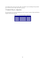
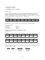
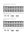
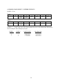
PCI-COM232 Series
User’s Manual
Revision 2
October, 2000
© Copyright 2000
LIFETIME WARRANTY
Every hardware product manufactured by Measurement Computing Corp. is warranted against defects in materials
or workmanship for the life of the product, to the original purchaser. Any products found to be defective will be
repaired or replaced promptly.
LIFETIME HARSH ENVIRONMENT WARRANTYTM
Any Measurement Computing Corp. product which is damaged due to misuse may be replaced for only 50% of the current price.
I/O boards face some harsh environments, some harsher than the boards are designed to withstand. When that happens, just return
the board with an order for its replacement at only 50% of the list price. Measurement Computing Corp. does not need to profit
from your misfortune. By the way, we will honor this warranty for any other manufacture’s board that we have a replacement
for!
30 DAY MONEY-BACK GUARANTEE
Any Measurement Computing Corp. product may be returned within 30 days of purchase for a full refund of the price paid for
the product being returned. If you are not satisfied, or chose the wrong product by mistake, you do not have to keep it. Please call
for a RMA number first. No credits or returns accepted without a copy of the original invoice. Some software products are
subject to a repackaging fee.
These warranties are in lieu of all other warranties, expressed or implied, including any implied warranty of
merchantability or fitness for a particular application. The remedies provided herein are the buyer’s sole and
exclusive remedies. Neither Measurement Computing Corp., nor its employees shall be liable for any direct or
indirect, special, incidental or consequential damage arising from the use of its products, even if Measurement
Computing Corp. has been notified in advance of the possibility of such damages.
MEGA-FIFO, the CIO prefix to data acquisition board model numbers, the PCM prefix to data acquisition board
model numbers, PCM-DAS08, PCM-D24C3, PCM-DAC02, PCM-COM422, PCM-COM485, PCM-DMM, PCMDAS16D/12, PCM-DAS16S/12, PCM-DAS16D/16, PCM-DAS16S/16, PCI-DAS6402/16, Universal Library,
InstaCal, Harsh Environment Warranty and Measurement Computing Corp. are registered trademarks of
Measurement Computing Corp.
IBM, PC, and PC/AT are trademarks of International Business Machines Corp. Windows is a trademark of
Microsoft Corp. All other trademarks are the property of their respective owners.
Information furnished by Measurement Computing Corp. is believed to be accurate and reliable. However, no
responsibility is assumed by Measurement Computing Corp. neither for its use; nor for any infringements of patents
or other rights of third parties, which may result from its use. No license is granted by implication or otherwise
under any patent or copyrights of Measurement Computing Corp.
All rights reserved. No part of this publication may be reproduced, stored in a retrieval system, or transmitted, in any form by any
means, electronic, mechanical, by photocopying, recording or otherwise without the prior written permission of Measurement
Computing Corp.
Notice
Measurement Computing Corp. does not authorize any Measurement Computing Corp. product
for use in life support systems and/or devices without the written approval of the President of
Measurement Computing Corp. Life support devices/systems are devices or systems which, a) are
intended for surgical implantation into the body, or b) support or sustain life and whose failure to
perform can be reasonably expected to result in injury. Measurement Computing Corp. products
are not designed with the components required, and are not subject to the testing required to
ensure a level of reliability suitable for the treatment and diagnosis of people.
HM PCI-COM232.doc
ii
TABLE OF CONTENTS
1.0 INTRODUCTION ............................................................................................................................1
2.0 INSTALLATION..............................................................................................................................2
2.1 Software Installation .....................................................................................................2
2.2 Hardware Installation....................................................................................................2
2.3 Set up the COM port parameters ..................................................................................3
2.4 Test the COM ports for proper operation (ComApp.exe).............................................3
2.5 Extended Baud Rate Operation.....................................................................................4
2.5.1 Windows 95/98 Specific Configuration.............................................................5
2.5.2 Windows NT/2000 Specific Configuration ......................................................5
2.5.3 Resetting Extended Baud Rate Selection on Power Up.....................................6
3.0 HARDWARE CONNECTIONS......................................................................................................7
3.1 Introduction...................................................................................................................7
3.2 DB9M Connections ......................................................................................................7
3.3 DB25M Connections ....................................................................................................7
3.4 PCI-COM232/4 Main DB37M Connector....................................................................8
3.5 Port Identification .........................................................................................................9
3.6 Changing the COM Port assignments...........................................................................9
3.7 Standard COM port configurations: .............................................................................10
4.0 REGISTER MAP..............................................................................................................................11
4.1 Register Map Overview ................................................................................................11
4.2 Register Descriptions....................................................................................................12
4.2.1 INTERRUPT STATUS/CONTROL..................................................................12
4.2.2 PORT 1 CLOCK SELECT / INTERRUPT STATUS .......................................12
4.2.3 PORT 2 CLOCK SELECT / INTERRUPT STATUS .......................................13
4.2.4 PORT 3 CLOCK SELECT / INTERRUPT STATUS .......................................13
4.2.5 PORT4 CLOCK SELECT / INTERRUPT STATUS ........................................14
5.0 SPECIFICATIONS ..........................................................................................................................15
6.0 TROUBLESHOOTING Q & A:......................................................................................................17
iii
This Page Intentionally Left Blank
iv
1.0 INTRODUCTION
The PCI-COM232 family consists of one, two and four port, RS-232 compatible, serial I/O boards
designed to operate in computers with PCI bus accessory slots. The package includes complete software
drivers for Windows 95, 98, NT and 2000 that allow the boards to be installed as standard “COM” ports
in your computer.
The boards are fully plug-and-play and provide an independent UART for each port. The boards provide
data and all standard RS-232 handshaking signals. They operate up to a maximum baud rate of 460.8
kbaud. All connections in the one and two port boards are made through standard DB9M connectors
while the four port board can be ordered with either DB9M or DB25M connectors.
The available models are shown in the table below.
Number
of Ports
1
1
On-Board Surge
Suppression
No
Yes
FIFO
Depth
16 bytes
16 bytes
PCI-COM232/2
PCI-COM232/2/S
2
2
No
Yes
16 bytes
16 bytes
PCI-COM232/4
PCI-COM232/4/S
4
4
No
Yes
16 bytes
16 bytes
Board
PCI-COM232
PCI-COM232/S
1
2.0 INSTALLATION
2.1 Software Installation
Insert the PCI-COM CD into your CD drive. If your systems auto-run feature is enabled the PCI-COM
Installation Wizard will automatically launch.
If the Installation Wizard does not auto-launch, you can initiate the software installation by running the
program SETUP.EXE on the CD. Do this by locating the CD’s SETUP.EXE file in your Windows
Explorer and double clicking on it. Assuming your CD drive is the E: drive, SETUP.EXE should be in E:\
Follow the Installation Wizard’s instructions and accept the default settings if possible.
2.2 Hardware Installation
The PCI-COM232 boards are completely plug-and-play. There are no switches or jumpers to set.
Configuration is controlled by your systems’ BIOS. To install the board, turn off your PC, unplug it, open
it, and insert your PCI-COM232 board into any available PCI slot.
The PCI-COM232 board is automatically assigned I/O addresses and Interrupts (IRQs) by your system
BIOS.
To check that all ports have been properly installed you may interrogate the COM port system with the
following sequence:
If you are using Windows 95 or 98
•
•
•
•
Right click on the “My Computer” Icon on your desktop
Click on “Properties”
Click on the “Device Manager” tab
Double click on the “Ports (COM & LPT)” Icon
If you are using Windows NT
•
•
•
Right click Start and then Settings on the Task Bar
Click on “Control Panel”
Click on the “Ports” icon
If you are using Windows 2000
•
•
•
•
Right click on the “My Computer” Icon on your desktop
Left click on “Manage”
Left click on “Device Manager”
Expand “Ports (COM & LPT)”
The new PCI-COM ports should be listed.
2
2.3 Set up the COM port p arameters
If you are using Windows 95, 98 or 2000
To set the com port parameters (e.g. standard baud rates, parity) follow the sequence listed above
for Windows 95, 98 and 2000, and then double click on the port you wish to configure. The
Communications Port (COM#) Properties sheet will appear. Click on the “Port Settings” tab and
change the port settings to match your applications requirements.
If you are using Windows NT
To set the com port parameters (e.g. standard baud rates, parity) use the Ports applet that can be
found in the Control Panel. Select the port you wish to configure and change the port settings to
match your applications requirements.
2.4 Test the COM ports for proper operation (ComApp.exe)
An application is provided that allows you to test your installation by communicating with another
RS-232 serial port. This test application is called ComApp.exe, and was installed during your driver
installation procedure. ComApp is a simple ASCII terminal emulator that automatically sends whatever
you type on the keyboard over the selected COM port, and automatically displays the data the COM port
receives.
You may use this application to test between two ports on the same PC, or install it on two PCs and test
communication between them. If you are installing a multi-port board, or you have a free RS-232 port in
addition to the one you are adding with the PCI–COM board, you can use the first method by running two
instances of ComApp on the same PC.
If your COM port is connected to a simple ASCII controlled device, use ComApp to test for proper
operation simply by typing one or more commands, and watching how the external device responds.
To launch ComApp.exe, you can find the file using your explorer and then double-click on it.
Alternatively, starting with your Windows Start button, follow this procedure:.
Start
Î Programs Î Measurement Computing Î ComApp
You can make a quick port communication test by connecting the PCI–COM board to another RS232
port, and sending/reading data between the two ports. You can use an RS-232 port on another PC or a free
RS-232 port on the same PC to which you are adding the PCI–COM board.
To do this test, install a null modem cable or adapter between the two ports. This serves to connect the
transmit pins from one port to the receive pins of the other and vice versa. Null modems adapters are
available at most computer stores or can be purchased from Measurement Computing Corp. (part #
SADP-25FM-NM for 25-pin, SADP-9FM-NM for 9-pin). To perform the test, follow the instructions
below:
1.
Connect the two ports via a null modem cable/adapter
2.
Launch the ComApp program (as described above)
3.
Select the Settings menu block and configure the first port.
3
Figure 2-1. TTY Settings
4.
Launch the ComApp again. You will get a second ComApp window. Go to the Settings
menu and configure the second port. Note that you must use the same settings on both ports
for this test to work properly.
5.
On both open ComApp windows, go to the Action menu and select Connect.
6.
Once connected, move the cursor to either ComApp window. Whatever is typed in that
window should be immediately displayed in the other. You may also test port operations by
selecting the Transfer menu and clicking on Send Data Block. A large block of ASCII
characters will automatically be sent, and should appear on the other ComApp window.
2.5 Extended Baud Rate O peration
Though it isn’t possible to set baud rates greater than 115.2 kbaud on the PCI-COM series using the
standard Windows Communications Port Properties dialog, the board and operating system are actually
capable of operating at transfer rates up to 460.8 kbaud. The PCI-COM series boards have a
programmable divider between the on-board system clock and the UART. This divider can be set using
the Advanced tab that was added to the Windows 95/98 Communications Port Properties dialog, or the
PCIcom applet added to the NT/2000 Control Panel during the PCI-COM software installation.
If the divider is set to divide-by-4 (the default setting) the board’s baud rate is exactly as Windows sets it.
If the divider is set to divide by two, all the actual board baud rates become double what Windows has set
them to, while if the divider is set to divide by one, the board’s baud rate is four times the baud rate set in
Windows. These selections are summarized in the table below. We have only shown the values for the
baud rates higher than normally supported by windows.
UART
Clock Rate
1.8432 MHz
3.6864 MHz
7.3728 MHz
Divider
4 (default)
2
1
Windows baud
rate setting
115.2 kbaud
115.2 kbaud
115.2 kbaud
4
Actual
baud rate
115.2 kbaud
230.4 kbaud
460.8 kbaud
Note: Please pay very close attention to your baud rate selections when using the extended baud rate
operating modes. The baud rate you select in windows will not be the actual baud rate setting of the PCICOM board, and it is easy to get confused regarding the speed at which the system is actually running.
2.5.1 Windows 95/98 Specific Co nfiguration
Extended baud rate operation is set on the COM port’s property page. To change to the enhanced baud
rate operating modes follow this procedure.
•
•
•
•
•
•
•
Right click on the “My Computer” Icon on your desktop
Click on “Properties”
Click on the “Device Manager” tab
Double click on the “Ports (COM & LPT)” Icon
Double click on the port you wish to configure
Click on the “Advanced” tab
Select the desired UART clock rate from the radio buttons as shown in Figure 2-2:
Figure 2-2. PCI-COM232 (Port1) (COM3) Properties Screen Display
2.5.2 Windows NT/2000 Specifi c Configuration
Under Windows NT the extended baud rate operation is set by the Control Panel Applet PciCom.cpl. To
change to the enhanced baud rate operating modes follow this procedure.
•
•
•
•
Click on the “Start” button on the left hand side of the task bar
Move the mouse to the “Settings” option and then click on “Control Panel”
Double click on the “PciCom” Icon
Select the desired UART clock rate from the radio buttons as shown in Figure 2-3:
5
Figure 2-3. PCI-COM232 Windows NT Control Panel Configuration
2.5.3 Resetting Extended Baud R ate Selection on Power Up
The PCI-COM232 board will power up with the UART Clock Rate set to 1.8432 MHz. If you change the
UART Clock Rate via the Device Manager Property Page (in Windows 95 or 98) or via the PCIcom
applet (in NT), you must execute the ComSet32.exe application to restore the settings after a reboot. The
Device Manager configuration dialog writes the chosen settings to the registry. The ComSet32.exe
application reads the settings from the registry and restores the PCI-COM232 hardware configuration.
During installation, the user has the option to install a shortcut to ComSet32.exe in the Startup folder. If
you select this option (YES), your PCI-COM232 hardware configuration is maintained across reboots. If
you select NO, at each reboot the PCI-COM232 board is restored to its default configuration.
Note: For most applications, the default settings for the hardware are adequate and allow the board to
operate at up to 115.2 kbaud.
If you selected NO during installation, when prompted about installing ComSet32.exe, then you can
manually create a shortcut and copy it to your Startup menu. The ComSet32.exe application is installed in
the directory specified during installation. The default installation directory is C:\cb. To create a shortcut,
do the following:
Start the “Windows Explorer” application and open the installation directory.
Right click on the “ComSet32.exe” entry.
Select the “Create Shortcut” option from the drop down menu.
Copy the shortcut to the Startup folder (C:\Windows\Start Menu\Programs\Startup).
To keep the ComSet32.exe window from popping up during execution, set the shortcut to execute
minimized. To set this option, do the following:
Right click on the shortcut icon and select Properties.
Select the shortcut tab.
Set the option labeled Run to “Minimized”.
6
3.0 HARDWARE CONN ECTIONS
3.1 Introduction
The PCI-COM232 and PCI-COM232/2 provide 9-pin male “D” (DB9M) connectors that extend through
the backplate of the board. There are two options for the PCI-COM232/4. The C37F-4X9M-1M is a cable
that splits the ports into separate DB9M connectors, while the C37F-4X25M-1M splits the 37-pin
connector into four ports with DB25M connectors.
3.2 DB9M Connections
The connectors on the PCI-COM232, PCI-COM232/2 boards and C37F-4X9M-1M cable all provide the
pin-out shown in Figure 3-1 below. The view shown is looking into the connector.
Figure 3-1. PCI-COM232 Board Connector Pinout
3.3 DB25M Connections
Cable C37F-4X25M-1M pinout is shown in Figure 3-2. The view is looking into the cable connector
13
25
12
24
11
23
10
22
RI
9
21
DCD
8
GND
7
DSR
6
CTS
5
RTS
4
RX
3
TX
2
20
DTR
19
18
17
16
15
14
1
Figure 3-2. Cable C37F-4X25M-1M Pinout
7
3.4 PCI-COM232/4 Main DB37M Connector
Although the PCI-COM232/4 boards provide a cable that brings the four ports out to standard 9- or 25pin serial connectors, customers wishing to wire directly to the board can refer to Figure 3-3. The view
shown is looking into the actual connector from outside the computer.
Figure 3-3. PCI-COM232/4 37-Pin Board-Connector Pinout
8
3.5 Port Identification
The PCI-COM232/4 ports are identified as Ports 1, 2, 3 or 4 directly on the RS-232 I/O connectors. The
PCI-COM232/2 port identities are shown in Figure 3-4 below:
Figure 3-4. PCI-COM232 Board Port Locations
3.6 Changing the COM Po rt assignments
In Windows 95/98, the PCI-COM ports are automatically installed, starting at COM5 if it is available, or
the next available port, if not. Other ports on multi-port boards will be assigned in numeric sequence after
the first port installed. If you wish to change the board’s initial COM Port number (e.g. from COM5: to
COM3), please follow the instruction provided below. Additional ports on the board will also be changed
so that the COM port assignments are sequential.
Right click on My Computer
Click on Properties
Click on the Device Manager tab
Click on MultiFunction.
Click on PCI-COM.
Click on Resources
Uncheck the Automatic Settings box
Note the I/O ranges listings. There will be one more range listed than the number of ports
provided on your board (e.g. the two port board will have three ranges listed). The first range +/10 is a shared interrupt status register and should not be changed. Subsequent ranges are the
actual COM port addresses.
Change the first port on your board to COM3: by following the instructions below.
Double click on the second I/O range listed. Highlight the complete listing type; 03e8-03ef and
click OK. Windows will then notify you that you have made changes that may affect other
devices. Click OK.
If you are installing a multi-port board, you will want to install the board’s second port as
COM4:. To do this double click on the third I/O range, highlight the complete listing type; 02e802ef and click OK. Once again windows will alert you that you have made modifications that
may affect other devices. Click OK.
9
Your COM ports have now been moved to COM3: and COM4:. If you are installing the four port board,
ports 3 and 4 now reside at COM5: and COM6: respectively.
3.7 Standard COM port c onfigurations:
The following table lists the standard configurations for PC serial ports. Typically, COM1 and COM2 are
assigned to the on-board serial ports.
Table 3-1. PC Serial Port Standard Configurations
Port Name
COM1
COM2
COM3
COM4
Address Range
0x3F8 – 0x3FF
0x2F8 – 0x2FF
0x3E8 – 0x3EF
0x2E8 – 0x2EF
10
Interrupt
4
3
4
3
4.0 REGISTER MAP
Although most users will take advantage of the COM driver supplied with the PCI-COM232 boards, the
following register map (Table 4-1) has information for users that may require it.
4.1 Register Map Overview
Table 4-1 Register Map
REGISTER
BADR1+4C h
READ FUNCTION
Interrupt Status
WRITE FUNCTION
Interrupt Control
Operations
32-bit dbl word
BADR2 + 0
BADR2 + 1
BADR2 + 2
BADR2 + 3
BADR2 + 4
BADR2 + 5
BADR2 + 6
BADR2 + 7
Port 1 UART
Port 1 UART
Port 1 UART
Port 1 UART
Port 1 UART
Port 1 UART
Port 1 UART
Port 1 Clock Sel Register
Port 1 UART
Port 1 UART
Port 1 UART
Port 1 UART
Port 1 UART
Port 1 UART
Port 1 UART
Interrupt Status Register
8-bit byte
8-bit byte
8-bit byte
8-bit byte
8-bit byte
8-bit byte
8-bit byte
8-bit byte
BADR3 + 0
BADR3 + 1
BADR3 + 2
BADR3 + 3
BADR3 + 4
BADR3 + 5
BADR3 + 6
BADR3 + 7
Port 2 UART
Port 2 UART
Port 2 UART
Port 2 UART
Port 2 UART
Port 2 UART
Port 2 UART
Port 2 Clock Sel Register
Port 2 UART
Port 2 UART
Port 2 UART
Port 2 UART
Port 2 UART
Port 2 UART
Port 2 UART
Interrupt Status Register
8-bit byte
8-bit byte
8-bit byte
8-bit byte
8-bit byte
8-bit byte
8-bit byte
8-bit byte
BADR4 + 0
BADR4 + 1
BADR4 + 2
BADR4 + 3
BADR4 + 4
BADR4 + 5
BADR4 + 6
BADR4 + 7
Port 3 UART
Port 3 UART
Port 3 UART
Port 3 UART
Port 3 UART
Port 3 UART
Port 3 UART
Port 3 Clock Sel Register
Port 3 UART
Port 3 UART
Port 3 UART
Port 3 UART
Port 3 UART
Port 3 UART
Port 3 UART
Interrupt Status Register
8-bit byte
8-bit byte
8-bit byte
8-bit byte
8-bit byte
8-bit byte
8-bit byte
8-bit byte
BADR5 + 0
BADR5 + 1
BADR5 + 2
BADR5 + 3
BADR5 + 4
BADR5 + 5
BADR5 + 6
BADR5 + 7
Port 4 UART
Port 4 UART
Port 4 UART
Port 4 UART
Port 4 UART
Port 4 UART
Port 4 UART
Port 4 Clock Sel Register
Port 4 UART
Port 4 UART
Port 4 UART
Port 4 UART
Port 4 UART
Port 4 UART
Port 4 UART
Interrupt Status Register
8-bit byte
8-bit byte
8-bit byte
8-bit byte
8-bit byte
8-bit byte
8-bit byte
8-bit byte
The single port PCI-COM232 board utilizes only Address range 1 and 2. The PCI-COM232/2 uses
Address range 1, 2 and 3 while the PCI-COM232/4 uses Address range 1 through 5.
11
4.2 Register Descriptions
4.2.1 INTERRUPT STATUS/CO NTROL
BADR1 + 4C hex
This register, and all 9052 registers, is 32 bits long. Since the rest of the register has specific control
functions, mask them off to access the interrupt control functions. INTE is the Interrupt Enable: 0 =
disabled, 1 = enabled (default). INTPOL is the Interrupt Polarity: 0 = active low (default), 1 = active high.
INT is the Interrupt Status: 0 = interrupt is not active, 1 = interrupt is active.
READ/WRITE
31:8
7
x
x
6
x
5
x
4
x
3
x
2
INT
1
INTPOL
0
INTE
The UART ports are 16C550 compatible. See any 16C550 data sheet for register functions.
AVAILABLE PORTS:
PCI-COM232:
PCI-COM232/2:
PCI-COM232/4:
PORT 1
PORTS 1-2
PORTS 1-4
4.2.2 PORT 1 CLOCK SELECT / INTERRUPT STATUS
BADR2 + 07 hex
READ
7
-
6
-
5
PORT1
CKSEL1
4
PORT1
CKSEL0
3
INT4
2
INT3
1
INT2
0
INT1
WRITE
7
-
6
-
5
PORT1
CKSEL1
4
PORT1
CKSEL0
3
-
2
-
1
-
0
-
INTx: Interrupt status for each port: the same signals are connected to this read register for all four ports.
CKSEL1:0 UART clock select. This allows transmission rates to 460.8 Kbaud and different rates on each
port. These settings are per port:
CKSEL1
0
0
1
CKSEL0
0
1
0
UART CLOCK
1.8432 MHz
3.6864 MHz
7.3728 MHz
12
Max Data Rate
115.2 kbaud
230.4 kbaud
460.8 kbaud
4.2.3 PORT 2 CLOCK SELECT / INTERRUPT STATUS
BADR3 + 07 hex
READ
7
-
6
-
5
PORT2
CKSEL1
4
PORT2
CKSEL0
3
INT4
2
INT3
1
INT2
0
INT1
WRITE
7
-
6
-
5
PORT2
CKSEL1
4
PORT2
CKSEL0
3
-
2
-
1
-
0
-
INTx Interrupt status for each port. The same signals are connected to this read register for all four
ports.
CKSEL1:0 UART clock select. This allows transmission rates up to 460.8 Kbaud and different data rates
on each port. These settings are per port:
CKSEL1
0
0
1
CKSEL0
0
1
0
UART CLOCK
1.8432 MHz
3.6864 MHz
7.3728 MHz
Max Data Rate
115.2 kbaud
230.4 kbaud
460.8 kbaud
4.2.4 PORT 3 CLOCK SELECT / INTERRUPT STATUS
BADR4 + 07 hex
READ
7
-
6
-
5
PORT3
CKSEL1
4
PORT3
CKSEL0
3
INT4
2
INT3
1
INT2
0
INT1
WRITE
7
-
6
-
5
PORT3
CKSEL1
4
PORT3
CKSEL0
3
-
2
-
1
-
0
-
INTx Interrupt status for each port. The same signals are connected to this read register for all four
ports.
CKSEL1:0
UART clock select. This allows for data rates to 460.8 Kbaud and different data rates on
each port. These settings are per port:
CKSEL1
0
0
1
CKSEL0
0
1
0
UART CLOCK
1.8432 MHz
3.6864 MHz
7.3728 MHz
13
Max Data Rate
115.2 kbaud
230.4 kbaud
460.8 kbaud
4.2.5 PORT4 CLOCK SELECT / INTERRUPT STATUS
BADR5 + 07 hex
READ
7
-
6
-
5
PORT4
CKSEL1
4
PORT4
CKSEL0
3
INT4
2
INT3
1
INT2
0
INT1
WRITE
7
-
6
-
5
PORT4
CKSEL1
4
PORT4
CKSEL0
3
-
2
-
1
-
0
-
CKSEL1:0
UART clock select. This allows transmission rates to 460.8 Kbaud and different data
rates on each port. These settings are per port:
CKSEL1
0
0
1
CKSEL0
0
1
0
UART CLOCK
1.8432 MHz
3.6864 MHz
7.3728 MHz
14
Max Data Rate
115.2 kbaud
230.4 kbaud
460.8 kbaud
5.0 SPECIFICATIONS
Typical for 25°C unless otherwise specified.
POWER CONSUMPTION
PCI-COM232
PCI-COM232/2
PCI-COM232/4
COMMUNICATIONS SPECIFICATIONS
UART Type
Baud Rate
INPUT/OUTPUT SECTION
Transceiver type
Transceiver Output Characteristics
Output Voltage Range
Short Circuit Current (infinite duration)
Propagation Delay (TTL to RS-232)
Output Enable
Output Disable
Transceiver Input Characteristics
Input Voltage Range
Propagation Delay (RS-232 to TTL)
Voltage Threshold
Vil
Vih
Hysteresis
+5V: 220 mA typical
+5V: 225 mA typical
+5V: 230 mA typical
16C550 with 16 byte FIFO
300 baud to 115.2 Kbaud standard mode
1200 baud to 460.8 Kbaud extended rate mode
SP211H
±5V min., ±7V typ
±25 mA
1 µs typ.
400 ns typ.
250 ns typ.
±15V
1.5 µs typ.
0.8V max
2.4V min
0.5V typ.
TRANSIENT VOLTAGE SUPPRESION OPTION (/S VERSION)
Board Description
PCI-COM232/S
PCI-COM232/2/S
PCI-COM232/4/S
Data Transceiver Input
Input Voltage Range (derated)
SP211H
±12V
TVS type
Working Peak Reverse Voltage
Breakdown Voltage
Peak Pulse Surge Current
Peak Pulse Power Dissipation
SMAJ12A
±12V
13.3V min., 14.7V max.
15.1 A max. (avalanche duration time = 10 µs)
300W max. (avalanche duration time = 10 µs)
Peak Pulse Power Dissipation is proportional to the
amount of time the TVS remains in the avalanche
mode. For specific power vs. avalanche timeduration information, consult the SMAJ12A
datasheet.
15
ENVIRONMENTAL
Operating temperature range
Storage temperature range
Humidity
0 to 70°C
−40 to 100°C
0 to 90% non-condensing
16
6.0 TROUBLESHOOTI NG Q & A:
The system does not recognize a mouse connected to the PCI-COM232 ports.
Some systems are not able to detect a mouse connected to ports on the PCI-COM232 board.
Future releases will address this problem. Therefore, currently it is best to assume that the mouse
will not work when connected to any of the PCI-COM232 ports.
The system was working before I rebooted and now no longer works.
The main issue with detecting the PCI-COM hardware involves the system-assigned base
address. The PCI-COM232 board relies on the Plug-n-Play capabilities of the system BIOS to
assign the base address for the COM ports. When new hardware is added to the machine, the
entire system is reconfigured. This might affect the addresses assigned to the PCI-COM232 board
and hence where the system detects the board. The easiest way to deal with this issue is to go into
the Device Manager and delete the “PCI-COM…” entry under the “Multi-Function” node. Now
reboot the system. This forces the system to reconfigure the PCI-COM232 board. After the
machine has rebooted, go back into the Ports entry under the Device Manager and configure the
Advanced settings. This forces the system to write the new settings to the registry. If you installed
the ComSet32.exe application in the Startup folder, the new configuration is restored after each
reboot.
I cannot configure an internal modem under Windows NT.
The PCI-COM installation replaces the standard Windows NT Serial.sys device driver with a
modified driver that supports the PCI-COM family of boards. The modified driver will work for
any of the boards in the PCI-COM family as well as the internal COM1 and COM2 ports.
However, there is an issue with the system being able to detect internal modems. This appears to
be a resource-related issue with the current implementation of the modified serial device driver.
Until this issue is resolved, internal modems are not supported on machines with PCI-COM
boards.
17
For your notes.
EC Declaration of Conformity
We, Measurement Computing Corp., declare under sole responsibility that the product:
PCI-COM232 series
Part Number
RS-232 interface for the PCI bus
Description
to which this declaration relates, meets the essential requirements, is in conformity with, and CE marking
has been applied according to the relevant EC Directives listed below using the relevant section of the
following EC standards and other informative documents:
EU EMC Directive 89/336/EEC: Essential requirements relating to electromagnetic compatibility.
EU 55022 Class B: Limits and methods of measurements of radio interference characteristics of
information technology equipment.
EN 50082-1: EC generic immunity requirements.
IEC 801-2: Electrostatic discharge requirements for industrial process measurement and control
equipment.
IEC 801-3: Radiated electromagnetic field requirements for industrial process measurements and control
equipment.
IEC 801-4: Electrically fast transients for industrial process measurement and control equipment.
Carl Haapaoja, Director of Quality Assurance
Measurement Computing Corporation
16 Commerce Boulevard,
Middleboro, Massachusetts 02346
(508) 946-5100
Fax: (508) 946-9500
E-mail: [email protected]
www. measurementcomputing.com