1
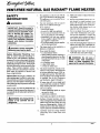
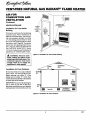
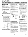
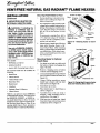
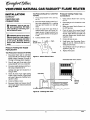
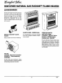
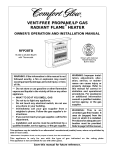
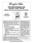
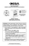
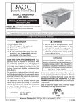
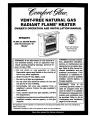
VENT-FREE
NATURAL GAS
RADIANT
FLAM
HEATER
OWNER'S
OPERATION
AND INSTALLATION
MANUAL
RFN28TC
14,000
with
to 28,000
Thermostat
Model
Btu/Hr
"C"
Shown with Optional
Mantel featuring
Built-in Base
not followed exactly, a fire or explosion may
result causing property damage, personal inI WARNING: If the information in this manual is
jury, or loss of life.
--Do
not store
or use gasoline
or other
flammable vapors and liquids in the vicinity of
this or any other appliance.
-- WHAT TO DO IF YOU SMELL GAS
•
•
•
Do not try to light any appliance.
Do not touch any electrical switch; do not use
any phone in your building.
Immediately
call your gas supplier
from a
neighbor's
phone. Follow the gas supplier's
instructions.
•
If you cannot reach your gas supplier,
fire department.
call the
m
Installation and service must be performed by a
qualified installer, service agency, or the gas
supplier.
WARNING: Improper installation, adjustment, alteration,
service, or maintenance can
cause injury or property damage. Refer to this manual for
correct installation and operational
procedures.
Fore
assistance or additional information consult a qualified
installer, service agency, or
the gas supplier.
WARNING:
This
is
an
unvented gas-fired heater. It
uses air (oxygen) from the
room in which it is installed.
Provisions for adequate combustion and ventilation must
be provided. Refer to Air for
Combustion and Ventilation,
page 6 of this manual.
This appliance may be Installed in an aftermarket* manufactured (mobile) home, where not prohibited by
state or local codes.
• Aftermarket: Completion of sale, not for purpose of resale, from the manufacturer
VENT-FREE NATURAL GAS RADIANT
SAFETY
INFORMATION
A,
WARNINGS
IMPORTANT: Read this owner's
manual carefully and completely
before trying to assemble, operate, or service this heater. Improper use of this heater can
cause serious injury or death from
burns, fire, explosion, electrical
shock, and carbon monoxide
poisoning.
This appliance is only for use with the
type of gas indicated on the rating plate.
This appliance is not convertible for use
with other gases.
Use only natural gas. Do not convert
heater to use different fuel type.
2.
3.
4.
_k DANGER: Carbon monoxide
poisoning may lead to death!
Carbon Monoxide Poisoning: Early
signs of carbon monoxide poisoningresemble the flu, with headaches, dizziness,
or nausea. If you have these signs, the heater
may not be working properly. Get fresh air
at onee! Have heater serviced. Some people
are more affected by carbon monoxide than
others. These include pregnant women,
people with heart or lung disease or anemia,
those under the influence of alcohol, and
those at high altitudes.
Natural Gas: Natural gas is odorless. An
odor-making agent is added to natural gas.
The odor helps you detect a natural gas leak.
However, the odor added to natural gas can
fade. Natural gas may be present even though
no odor exists.
Make certain you read and understand all
warnings. Keep this manual for reference. It
is your guide to safe and proper operation of
this heater.
5.
6.
7.
8.
9.
heater or Its controls can be
_kWARNING: Any changeto this
dangerous.
If you smell gas
• shut off gas supply
• do not try to light any appliance
• do not touch any electrical switch; do
not use any phone in your building.
• immediately call your gas supplier
from a neighbor's phone. Follow the
gas supplier's instructions
• if you cannot reach your gas supplier,
call the fire department
This heater shall not be installed in a
bedroom or bathroom.
Never install the heater
• in a recreational vehicle
• where curtains, furniture, clothing, or
other flammable objects are less than
36 inches from the front, top, or sides
of the heater
• asa fireplace insert
• in high traffic areas
• in windy or drafty areas
This heater needs fresh, outside air ventilation to run properly. This heater has
an oxygen depletion sensor (ODS) pilot light safety system. The ODS shuts
down the heater if not enough fresh air
is available. See Air for Combustion
and Ventilation, pages 6 through 8.
FLAME HEATER
12. Make sure screen is in place before running heater.
13. Before using furniture polish, wax, carpet cleaner, or similar products, turn
heater off. If heated, the vapors from
these products may create a white powder residue within burner box or on
adjacent walls or furniture.
14. Do not use heater if any part has been
under water. Immediately
call a qualified service technician to inspect the
room heater and to replace any part of
the control system and any gas control
which has been under water.
15. Turn off and unplug heater and let cool
before servicing. Only a qualified service person should service and repair
heater.
16. Operating heater above elevations of
4,500 feet may cause pilot outage.
_.
WARNING:
Do not use a I
blower insert, heat exchanger
insert, or other accessory not
approved for use with this heater.
If heater shuts off, do not relight until
you provide fresh, outside air. If heater
keeps shutting off, have it serviced.
Do not run heater
• where flammable liquids or vapors
are used or stored.
• under dusty conditions.
Never place any objects on the heater.
10. Surface of heater becomes very hot
when running heater. Keep children and
adults away from hot surface to avoid
burns or clothing ignition. Heater will
remain hot for a time after shutdown.
Allow surface to cool before touching.
ll. Carefully supervise young children
when they are in same room with
heater.
2
I035(_
OWNER'S
PRODUCT
IDENTIFICATION
PRODUCT
FEATURES
Control Knob
Ignitor Button
MANUAL
/
Operation
Lighting and
Warning
Plates
This heater is clean burning. It requires no
outside venting. This heater has been tested and
approved to ANS Z21.11.2 standard for
unvented heaters. State and local codes in some
areas prohibit the use of vent-free heaters.
Safety Pilot
Note: Do not
remove lighting
and warning
plates from
heater.
Heater
Cabinet
Screen
This heater has a pilot with an Oxygen
Depletion Sensor Shutoff System (ODS).
The ODS/pilot is a required feature for ventfree room heaters. The ODS/pilot shuts off
the heater if there is not enough fresh air.
Piezo Ignition
Front
Panel
Log
System
This heater has a piezo ignitor. This system
requires no matches, batteries, or other
sources to light heater.
Thermostatic
Heat Control
This heater has a thermostat sensing bulb
and a control valve. This results in the greatest heater comfort. This can also result in
Figure 1 - Vent*Free Gas Log Natural Gas Space Heater
LOCAL
CODES
UNPACKING
Install and use heater with care. Follow all
local codes. In the absence of local codes, use
the latest edition of The National Fuel Gas
Code ANS Z223, also known as NFPA 54*.
CAUTION: Do not remove the
metal data plates attached to the
heater. The data plates contain
important warranty information.
*Available from:
American National Standards Institute, Inc.
1430 Broadway
New York, NY 10018
National Fire Protection Association, Inc.
Batlerymarch Park
Quincy, MA 02269
_oo.._oe
lower gas bills.
1.
Remove
heater from carton.
2.
Remove all protective packaging applied to heater for shipment.
3.
Make sure your heater includes two
hardware packets.
4.
Check heater for any shipping damage.
If heater is damaged, promptly inform
dealer where you bought heater.
3
VENT-FREE NATURAL GAS RADIANT
ASSEMBLY
ASSEMBLING
HEATER
Tools Required:
• Phillips screwdriver
• 5116" hex wrench
• Slotted screwdriver
Removing Front Panel Of Heater
1. Remove two screws near bottom corners of front panel with Phillips screwdriver.
2.
_, WARNING:
Always have
burner shield and screen in place
before operating heater. This prevents excessive temperatures on
heater surfaces.
Failure to position the parts in
accordance with these diagrams
or failure to use only parts specifically approved with this heater
may result in property damage or
personal injury.
FLAME HEATER
Attaching Brass Front Trim to
Front Panel
1.
2.
3.
Locate brass front trim in brass trim
package.
Slide the head of two truss-head screws
from hardware packet into each end of
brass front trim (see Figure 5).
Line up screws with holes in front panel
(see Figure 4). Insert screws in holes.
Attach nuts from inside of front panel.
Tighten with wrench.
Piezo Ignitor
Pull bottom of front panel forward, then
down (see Figure 2).
Front
Panel
Brass Front
Screw
Nut
Figure 5 - Attaching Brass Front Trim to
Front Panel
Figure 2 . Removing Front Panel of Heater
Installing
Log
Note: For easier installation, lay heater on
its back.
1.
Remove log from inside top of heater.
Discard protective packaging.
2.
Attach ignitor cable to piezo ignitor
(see Figure 3).
3.
With Phillips screwdriver, remove four
screws holding screen in place. Remove screen.
4.
Gently slide log between log retaining
brackets on deflector assembly (see Figure 4). The log should fit firmly against
bottom of log retaining brackets.
Ignitor Cable
Figure 3 -Attaching Ignitor Cable to Plezo
Ignitor
Heater Cabinet
Log
I
5.
I
Log
Retaining
. Brackets
Front Panel
TrussHead
Screw
Reattach screen using four screws removed in step 3.
Screw
BurnerShield
Brass
Figure
4 - Assembling
Heater
4
1o35_
OWNER'S
MANUAL
ASSEMBLY
Continued
Assembling
Brass Trim
1.
2.
Top Brass Trim
Side Brass Trim
Set Screws
and Attaching
Adjusting
Plate
Remove packaging from remaining
three pieces of brass trim.
Locate four brass screws, two adjusting plates with set screws, and two
shims in the hardware packet.
3.
Align shim under adjusting plate as
shown in Figure 6.
Shi;
4.
Slide one end of adjusting plate/shim
in slot on mitered edge of top brass trim
(see Figure 6).
Mitered Edge
5.
6.
Slide other end of adjusting plate/shim
in slot on mitered edge of side brass
trim (see Figure 6).
While firmly holding edges of brass
trim together, tighten both set screws
on the adjusting plate with slotted
screwdriver.
7.
8.
Repeat steps I through 6 for other side.
Place the assembled trim on front of
heater cabinet. Attach on top and sides
with four brass screws included in hardware package (see Figure 7).
9.
Reattach front panel to heater if you are
going to mount the heater to the base.
Do not re,attach front panel at this time
if you are going to mount heater to wall.
Slot
Slot
Figure 6 - Assembling Brass Trim
Screws
Assembled
Brass Trim
Figure 7 - Attaching Brass Trim to Heater
10350S
5
VENT-FREE NATURAL GAS RADIAN'I
AIR FOR
COMBUSTION
VENTILATION
AND
WARNING: This heater shall
not be installed In a confined space
or unusually tight construction
unless provisions are provided
for adequate combustion and ventilation air. Read the following instructions to insure proper fresh
air for this and other fuel-burning
appliances in your home.
Today's homes are built more energy efficient than ever. New materials, increased
insulation, and new construction methods
help reduce heat loss in homes. Home owners
weather strip and caulk around windows and
doors to keep the cold air out and the warm air
in. During heating months, home owners
want their homes as airtight as possible.
While it is good to make your home energy
efficient, your home needs to breathe. Fresh
air must enter your home. All fuel-burning
appliances need fresh air for proper combustion and ventilation.
Exhaust fans, fireplaces, clothes dryers, and
fuel burning appliances draw air from the
house to operate. You must provide adequate fresh air for these appliances. This
will insure proper venting of vented fuelburning appliances.
PROVIDING ADEQUATE
VENTILATION
Confined
The following are excerpts from National
Fuel Gas Code. NFPA 54/ANS Z223.1, Section 5.3, Air for Combustion and Ventilation.
All spaces in homes fall into one of the three
following ventilation classifications:
1.
Unusually Tight Construction
2.
Unconfined Space
3.
Confined Space
The information on pages 6 through 8 will
help you classify your space and provide
adequate ventilation.
Unusually
Tight Construction
The air that leaks around doors and windows may provide enough fresh air for
combustion and ventilation. However, in
buildings of unusually tight construction,
you must provide additional fresh air.
Unusually tight construction
fined as construction where:
FLAME HEATER
is de-
a°
walls and ceilings exposed to the
outside atmosphere have a continuous water vapor retarder with
a rating of one perm (6x10 "11kg
per pa-sec-m =)or less with openings gasketed or sealed and
b.
weather
stripping
has been
added on openable windows and
doors and
g.
caulking or sealants are applied
to areas such as joints around
window and door frames, between sole plates and floors, between wall-ceiling
joints, between wall panels, at penetrations for plumbing, electrical, and
gas lines, and at other openings.
and Unconfined
Space
The National Fuel Gas Code (ANS Z223. l,
1992 Section 5.3) defines a confined space
as a space whose volume is less than 50
cubic feet per 1,000 Btu per hour (4.8 m 3per
kw) of the aggregate input rating of all
appliances installed in that space and an
unconfining space as a space whose volume
is not less than 50 cubic feet per 1,000 Btu
per hour (4.8 m 3per kw) of the aggregate
input rating of all appliances installed in that
space. Rooms communicating directly with
the space in which the appliances are installed*, through openings not furnished
with doors, are considered a part of the
unconfined space.
This heater shall not be installed in a confined space or unusually tight construction
unless provisions are provided for adequate
combustion and ventilation air.
* Adjoining rooms are communicating only
if there are doorless passageways or ventilation grills between them.
If your home meets all of the three
criteria above, you must provide additional fresh air° See Ventilation Air
From Outdoors, page 8.
If your home does not meet all of the
three criteria above, proceed to Determining Fresh-Air Flow for Heater
Location, page 7.
6
f_
OWNER'S
AIR FOR
COMBUSTION
VENTILATION
MANUAL
AND
Continued
DETERMINING
FRESH-AIR
FLOW FOR HEATER
LOCATION
Determining if You Have a Confined or Unconfined Space
Use this worksheet to determine if you have a confined or unconfined space.
Space: Includes the room in which you will install heater pl us any adjoining rooms with doorless passageways or ventilation grills between
the rooms.
1.
Determine the volume of the space (length x width x height).
Length x Width x Height =
2.
cu. ft. (volume of space)
Example: Space size 20 ft. (length) x 16 ft. (width) x 8 ft. (ceiling height) = 2560 cu. ft. (volume of space)
If additional ventilation to adjoining room is supplied with grills or openings, add the volume of these rooms to the total volume of
the space.
Divide the space volume by 50 cubic feet to determine the maximum Btu/Hr the space can support.
(volume of space) ÷ 50 cu. ft. = (Maximum Btu/Hr the space can support)
Example: 2560 cu. ft. (volume of space) ÷ 50 cu. ft. =51.2 or 51,200 (maximum Btu/Hr the space can support)
3.
Add the Btu/Hr of all fuel burning appliances in the space.
Vent-free heater
Btu/Hr
Gas water heater*
Gas furnace
Btu/Hr
Btu/FIr
Vented gas heater
Btu/Hr
Vent-free heater
+ 28,000 Btu/Hr
Gas fireplace logs
Btu/Hr
Total
= 58,000 Btu/Hr
Other gas appliances*
Total
+
=
Example:
Gas water heater
30,000 Btu/Hr
Btu/Hr
Btu/Hr
* Do not include direct-vent gas appliances. Direct-vent draws combustion air from the outdoors and vents to the outdoors.
4.
Compare the maximum Btu/Hr the space can support with the actual amount of Btu/Hr used.
Btu/Hr (maximum the space can support)
Btu/Hr (actual amount of Btu/l-lr used)
Example:
51,200 Btu/Hr (maximum the space can support)
58,000 Btu/Hr (actual amount of Btu/Hr used)
The space in the above example is a confined space because the actual Btu/Hr used is more than the maximum Btu/Hr the space can support.
You must provide additional fresh air. Your options are as follows:
A. Rework worksheet, adding the space of an adjoining room. If the extra space provides an unconfined space, remove door to adjoining room or add ventilation grills between rooms. See Ventilation Air From Inside Building, page 8.
B. Vent room directly to the outdoors. See Ventilation Air From Outdoors, page 8.
C. Install a lower Btu/Hr heater, if lower Btu/Hr size makes room unconfined.
If the actual Btu/Hr used is less than the maximum Btu/I-lr the space can support, the space is an unconfined space. You will need no
additional fresh air ventilation.
WARNING: If the area In which the heater may be operated Is smaller than that defined as an unconfined space
or If the building is of unusually tight construction,
provide adequate combustion and ventilation air by one of
the methods described in the National Fuel Gas Code, ANS Z223.1, 1992, Section 5.3, or applicable local codes.
Continued
103508
7
VENT-FREE NATURAL GAS RADIANT
AIR FOR
COMBUSTION
FLAME HEATER
AND
VENTILATION
Continued
VENTILATION
Ventilation
Ventilation Grills
Into Adjoining Room,
Option 2
AIR
Air From Inside
Building
Ventilation
Grills
into Adjoining
Room,
Option 1
This fresh air would come from an adjoining
unconfined space. When ventilating to an
adjoining unconfined space, you must provide two permanent openings: one within
12" of the ceiling and one within 12" of the
floor on the wall connecting the two spaces
(see options 1 and 2, Figure 8). You can also
remove door into adjoining room (see option 3, Figure 8). Follow the National Fuel
Gas Code NFPA 54/ANS Z223.1, Section
5.3, Air for Combustion and Ventilation for
required size of ventilation grills or ducts.
WARNING:
Rework
work-
Figure 8 - Ventilation Air from Inside Building
sheet, adding the space of the
adjoining unconfined space, The
combined spaces must have
enough fresh air to supply all
appliances in both spaces.
Ventilation
Air From Outdoors
Provide extra fresh air by using ventilation
grills or ducts. You must provide two permanent openings: one within 12" of the
ceiling and one within 12" of the floor.
Connect these items directly to the outdoors
or spaces open to the outdoors.
IMPORTANT:
inlet or outlet
Do not provide openings for
air into attic if attic has a
thermostat-controlled power vent. Heated air
entering the attic will activate the power vent.
Outlet
Air
To Attic
To
Crawl
Space
Inlet
Air
Inlet Air
Ventilated
Crawl Space
Figure 9 - Ventilation Air from Outdoors
8
1035t_
OWNER'S
INSTALLATION
NOTICE: This heater is intended
for use as supplemental heat. Use
this heater along with your primary heating system. Do not Install this heater as your primary
heat source. If you have a central
heating system, you may run
system's circulating blower while
using heater. This will help circulate the heat throughout
the
house. In the event of a power
outage, you can use this heater
as your primary heat source.
NOTICE: A qualified service person must install heater. Follow
all local codes.
CHECK
LOCATING
HEATER
WARNING: Maintain the minimum clearances shown in Figure
10. If you can, provide greater
clearances from floor, ceiling, and
joining wall.
You can locate heater on floor. The optional
hearth base is needed. You can also install
the optional decorative mantel on the heater
(some mantels require hearth base).
IMPORTANT" Only use optional mantel
and hearth base specified in this manual.
Purchase the optional mantel and hearth
base from your dealer. See Accessories,
pages 24 and 25.
The heater may also be mounted on a wall.
You cannot use optional mantel if mounting
heater on a wall.
MANUAL
_, CAUTION: If you install the
heater in a home garage
• heater pilot and burner must
be at least 18 inches above
floor.
• locate heater where moving vehicle will not hit it.
Forconvenience andefficiency, install heater
• where there is easy access for operation,
inspection, and service.
• in coldest part of room.
An optional fan kit is available from your
dealer. See Accessories, pages 24 and 25. If
planning to use fan, locate heater near an
electrical outlet.
CEIUNG
GAS TYPE
Use only natural gas. If your gas supply is
not natural gas, do not install heater. Call
dealer where you bought heater for proper
type heater.
INSTALLATION
ITEMS
Before in,tailing heater, make sure you have
the items listed below.
piping (check local codes)
sealant (resistant to propane/LP gas)
manual shutoff valve *
WARNING: Never install the
heater
• in a bedroom or bathroom
• in a recreational vehicle
• where curtains,
furniture,
clothing, or other flammable
objects are less than 36 inches
from the front, top, or sides of
the heater
• as a fireplace Insert
• in high traffic areas
• in windy or drafty areas
,36"
Minimum
Right
Side
S"
---L
FLOOR
Minimum to Top
Sudace of Carpeting,
Tile or Other
ground joint union
test gauge connection *
sediment trap
tee joint
pipe wrench
• An A.G.A. design-certified manual shutoff
valve with 1/8" NPT tap is an acceptable
alternative to test gauge connection. Purchase the optional A.G.A. design-certified
manual shutoff valve from your dealer. See
Accessories, pages 24 and 25.
Combustible Material
_1= CAUTION: This heater creates warm air currents. These
currents move heat to wall surfaces next to heater. Installing
heater next to vinyl or cloth wall
coverings or operating heater
where impurities (such as tobacco smoke, aromatic candles,
cleaning fluids, oil or kerosene
lamps, etc.) in the air exist, may
discolor walls.
IMPORTANT:
Vent-free
Figure 10 - Mounting Clearances
Viewed From Front of Heater
As
heaters add mois-
ture to the air. Although this is beneficial,
installing heater in rooms without enough
ventilation air may cause mildew to form
from too much moisture. See Air for Combustion and Ventilation, pages 6 through 8.
Continued
_a35o0
9
VENT-FREE NATURAL GAS RADIANT
iNSTALLATiON
INSTALLATION
Continued
There are three options
heater.
THERMOSTAT
BULB
SENSING
The thermostat sensing bulb has been placed
inside the heater for protection during shipping.
Locating
Bulb
1.
2.
Thermostat
Sensing
Remove front panel of heater (see Figure 2, page 4).
Locate thermostat sensing bulb just
under burner assembly.
IMPORTANT." Attach thermostat sensing
bulb to back of heater for proper operation.
Attaching
Bulb
Thermostat
for mounting
A. Mounting
heater to wall
B. Mounting
heater to optional
Mounting
this
1.
hearth base
C. Mounting heater with optional
base to optional mantel
A. MOUNTING
WALL
Marking
Tape mounting bracket to wall where
heater will be located. Make sure
mounting bracket is level.
_WARNING:
Maintain minimum
clearances shown In Figure 13. If
you can, provide greater clearances from floor and joining wall.
hearth
HEATER TO
2.
Bracket
The mounting bracket is located on back
panel of heater. It has been taped there for
shipping. Remove mounting bracket from
back panel.
Screw Locations
Mark screw locations on wall (see Figure 13).
Note: Only mark last hole on each end
of mounting bracket. Insert mounting
screws through these holes only.
3.
Remove tape and mounting bracket
from wall.
Sensing
1.
Remove thermostat sensing bulb from
holders inside heater. Route through
slot opening in bottom of heater.
2.
Place clamp on thermostat sensing bulb
as shown in Figure 11. Clamp is provided in hardware package.
3.
OPTIONS
FLAME HEATER
Snap clamp into upper mounting hole
as shown in Figure I 1. Mounting hole
is located on lower left edge on back
of heater. Make sure the thermostat
sensing bulb is pointing up.
Thermostat
Bulb
\
Figure 12 - Mounting Bracket Location
Methods For Attaching
Mounting Bracket To Wall
Only use last hole on each end of mounting
bracket to attach bracket to wall. These two
holes are 16 inches apart from their centers.
Attach mounting bracket to wall in one of
two ways.
2. Attaching to wallancbor
Attaching To Wall Stud This method
provides the strongest hold. Insert mounting
screws through mounting bracket and into
wall studs.
Figure 11 - Attachlng Thermostat Sensing
Bulb
I
20 3/4"
Min.
Mounting
Bracket
1. Attaching to wall stud
Clamp
/
Only Insert Mounting
Screws Through Last
Hole On Each End
Attaching To Wall Anchor This method
allows you to attach mounting bracket to
hollowwails (wall areasbetweenstuds)or
to solid walls(concreteor masonry).
Decide which method better suits your needs.
Either method will provide a secure hold for
the mounting bracket.
10
Figure 13. Mounting Bracket Clearances
Attaching
Wall
Mounting
Bracket To
Note: Wall anchors, mounting screws, and
spacers are in hardware package. The hardware package is provided with heater.
Attaching
To Wall Stud Method
For attaching mounting bracket to wall studs
1.
Drill holes at marked locations using
9/64" drill bit.
2.
Place mounting bracket onto wall. Line
up last hole on each end of bracket with
holes drilled in wall.
3.
Insert mounting screws through bracket
and into wall studs.
4.
Tighten screws until mounting bracket
is firmly fastened to wall studs.
t 03.,_a
OWNER'S
INSTALLATION
Continued
Placing Heater On Mounting
Bracket
1.
Attaching
To Wall Anchor Method
For attaching mounting bracket to hollow
wails (wall areas between studs) or solid
walls (concrete or masonry)
1.
Drill holes at marked locations using
5/16" drill bit. For solid wails (concrete
or masonry), drill at least 1" deep.
2.
Fold wall anchor as shown in Figure 14.
3.
Insert wall anchor (wings first) into
hole. Tap anchor flush to wall.
For thin walls (1/2" or less), insert
red key into wall anchor. Push red
key to "pop" open anchor wings.
IMPORTANT: Do not hammer key!
4.
Locate
Place mounting bracket onto wall. Line
up last hole on each end of bracket with
wall anchors.
6.
Insert mounting screws throughbracket
and into wall anchors.
7.
Tighten screws until mounting bracket
is firmly fastened to wall.
2.
Place heater onto mounting bracket.
Slide horizontal
slots onto stand-out
tabs on mounting
bracket.
Tighten both screws until heater is
firmly secured to wall. Do not over
tighten.
Note: Do not replace front panel at this
time. Replace front panel after making
gas connections and checking for leaks
(see pages 13 and 14).
Horizontal Slots
S
Stand-Out
Tab
Mounting Bracket
(attached to wall)
Figure 16 - Mounting
Mounting Bracket
Installing
Screws
1.
Bottom
Heater
Figure 17 - Installing Bottom Mounting
Screws
Onto
Mounting
Locate two bottom mounting
holes.
These holes are near bottom on back
2.
panel of heater (see Figure 17).
Mark screw locations on wall.
3.
Remove heater from mounting bracket.
4.
If installing bottom mounting screws
into hollow or solid wall, install wall
anchors. Follow steps 1 through 4 under Attaching To Wall Anchor Method.
If installing bottom mounting screw
into wall stud, drill holes at marked locations using 9/64" drill bit.
Figure 14 - Folding Anchor
5.
6.
7.
Figure 15- Popping Open Anchor Wings
For Thin Walls
slots on back
panel of heater.
For thick walls (over 1/2" thick) or solid
walls, do not pop open wings.
5.
two horizontal
8.
MANUAL
Replace heater onto mounting bracket.
Place spacers between bottom mounting holes and wall anchor or drilled hole.
Hold spacer in place with one hand.
With other hand, insert mounting screw
through bottom mounting hole and
spacer. Place tip of screw in opening
of wall anchor or drilled hole.
Continued
w3_a
11
VENT-FREE NATURAL GAS RADIANT a)FLAME HEATER
INSTALLATION
Securing
Continued
1.
Position hearth base in desired location.
Mark holes for drilling (See Figure 18).
Remove hearth base.
2.
For carpeted floor, make a small cut with
a sharp knife at marked locations before
drilling. If securing to a wood floor, drill
a 3/4" deep hole using a 1/8" diameter
drill bit. Do not use anchors in wood
floors.
B. MOUNTING HEATER ON
OPTIONAL HEARTH BASE
WARNING: If installing the
GHB802 or GHB802A base on
heater, and using with a GA series heater blower accessory
along with a GS601 surround or a
GM800 or GM900 series mantel,
the surround or mantel clearance
to back wall should be 3/4 inch.
This will improve flame appearance and combustion.
Hearth Base to Floor
If securing to a concrete floor, drill a
1 Vs" deep hole using a 1/4" diameter
concrete drill bit. Completely
insert
anchors into each hole.
3.
Use only s GHB802B, GHB802C,
or GHB38 series hearth base if
using a GA series heater blower
accessory with a GM700 series,
GMC32F series, or GMC33U series mantel.
Mount heater to hearth base following
steps under Mounting Heater to Optional Hearth Base. After mounting
heater, position heater and hearth base
over drilled holes. With slotted screwdriver, secure hearth base to floor with
four
wood
Tools needed:
• #2 Phillips screwdriver
• slotted screwdriver
h
The optional hearth base kit includes the
following:
Hearth Base
4 Wood Screws
4 Sheet Metal Screws
Brass Base Trim
Remove 2 shipping screws in bottom
of heater. Discard shipping screws.
3.
Line up mounting holes on top of hearth
base with holes in bottom of heater (see
Figure 18).
Hearth Insert
4 Anchors
Laminate Sheet & Adhesive
5.
6.
2 Brass Screw_;
Note: It is an option to secure GI-IB802A
model hearth base to floor. You must secure
the GHB802B, GItB802C, or GI-IB38 series model hearth base to floor. To secure
hearth base to floor, follow instructions under Securing Hearth Base to Floor If not
securing hearth base to floor, proceed to
Mounting Heater to Optional Hearth Base.
7.
8.
Figure 18 - Attaching
Base
Mounting
Holes
\ Sheet Metal
Screw
Heater to Hearth
LaminateSheet
\
Hearth
Insert
Lay heater on its back on a table with
the bottom of heater overhanging the
edge of the table.
2.
4.
Holes for
Securing
Heater to Floor
screws.
Mounting Heater to Optional
Hearth Base
• electric drill (if securing base to floor)
Bottom of Heater
Base
Shipping
Screw
Using a Phillips screwdriver, secure
hearth base to heater with four sheet
metal screws (see Figure 18).
Screw
_
Brass Base Trim
Figure 19- Placing Hearth Insert on Heater
Base and Attaching Brass Base Trim
Stand heater up on base.
Place hearth insert in hearth base as
shown in Figure 19.
Assemble brass trim (see steps 1
through 7 under Assembling and Attaching Brass Trim, page 5).
Slide base trim on heater base. Attach
brass trim to base with two brass screws
included as shown in Figure 19.
12
lo_oe
OWNER'S
INSTALLATION
Continued
C. MOUNTING HEATER WITH
OPTIONAL HEARTH BASE
TO OPTIONAL MANTEL See
instructions included with
mantel kit.
Assembling
Mantel
IMPORTANT:
Only use the optional mantels specified in this manual. See Accessories, pages 24 and 25 for proper mantel kits.
This heater is only approved for use with
models
GMF800(A,B
)/GMU801 (A,B),
GMg00F(A,B)/GM901U(A,B),
GM700F/
GM701U, GMC22F/GMC23U/GMC24U,
GMC32F(B)/GMC33U(B),
and GMC26F/
GMC27U/GMC28F
mantel kits. Using any
other mantel will void the A.G.A. approval
for this heater.
Do not use models
GMF800(A,B)/GMU80
1 (A,B),
GM900F(A,B)/GM901U(A,B),
and
GM70OF/GM701U,
GMC22F/GMC23U/
GMC24U, GMC32F(B)/GMC33U(B),
and
GMC26F/GMC27U/GMC28F
mantels with
any other product. Before installing mantel
to heater, the heater must be mounted on the
optional hearth base.
Installing
CONNECTING
SUPPLY
NOTICE: A qualified service person must connect heater to gas
supply. Follow all local codes.
WARNING: Never connect
heater to private (non-utility) gas
wells. This gas is commonly
known as wellhead gas.
IMPORTANT: Check gas line pressure before connecting heater to gas line. Gas line
pressure must be no greater than 14 inches
of water. If gas line pressure is higher,
heater regulator damage could occur.
CAUTION : Use only new,
black iron or steel pipe. Internally-tinned copper tubing may
be used in certain areas. Check
your local codes. Use pipe of 1/2"
or greater
diameter to allow
proper gas volume to heater. If
pipe is too small, undue loss of
pressure will occur.
Use only a GHB802B, GHB802C,
OR GHB38 series hearth base if
using a GA series heater blower
accessory with a GM70O series,
GMC32F series, or GMC33U series mantel.
Installation must include a manual shutoff
valve, union, and plugged 1/8" NPT tap.
Locate NPT tap within reach for test gauge
hook up. NPT tap must be upstream from
heater (see Figure 20).
Apply pipe joint sealant lightly to male
threads. This will prevent excess sealant
from going into pipe. Excess sealant in pipe
could result in clogged heater valves.
_k CAUTION: Use pipe ioint sealant that is resistant to liquid petroleum (LP) gas.
Install sediment trap in supply line as shown
in Figure 20. Locate sediment trap where it
is within reach for cleaning. Locate sediment trap where trapped matter is not likely
to freeze. A sediment trap traps moisture
and contaminants. This keeps them from
going into heater controls. If sediment trap
is not installed or is installed wrong, heater
may not run properly.
_k CAUTION: Avoid damage to
control. Hold gas fitting with
wrench when connecting it to gas
piping and/or fittings.
Pressure
Regulator _
Mantel to Heater
_k WARNING: If installing the
GHB802 or GHB802A base on
heater, and using with a GA series heater blower accessory
along with a GS601 surround or a
GM800 or GM900 series mantel,
the surround or mantel clearance
to back wall should be 3/4 inch.
This will improve flame appearance and combustion.
TO GAS
MANUAL
Note: Burner
bracket not
shown for clarity
3/8" NPT
Pipe
Cabinet
Joint
nual Shutoff Valve *
Test
Gauge
Connection *
(4" W.C. to 10.5° W.C.
Pressure)
Sediment
_;Minimum
Trap
-Cap
Figure 20 - Gas Connection
* An A.G.A. design-certified manual shutoff valve with !/8" NPT tap is an acceptable
alternative to test gauge connection. Purchase the optional A.G.A. design-certified
manual
shutoff valve from your dealer. See Accessories,
pages 24 and 25.
Continued
to35_e
13
VENT-FREE
NATURAL
INSTALLATION
Continued
2.
in_gWARNING:
Test allfor
gasleaks
pip"
and connections
after installing or servicing. Correct all leaks at once.
_I_WARNING: Never use an open
flame to check for a leak. Apply a
mixture of liquid soap and water
to all joints. Bubbles forming
show a leak. Correct all leaks at
once.
3.
4.
5,
6.
3.
4.
Pressurize supply piping system by either using compressed air or opening
main gas valve located on or near gas
meter.
Check all joints from gas meter to
manual shutoff valve (see Figure 22).
Apply mixture of liquid soap and water to gas joints. Bubbles forming show
a leak.
FLAME HEATER
Pressure Testing
Connections
Open manual shutoff valve (see Figure 21).
2.
Open main gas valve located on or near
gas meter.
Make sure control knob of heater is in
the OFF position.
3.
4.
5.
Manual
_
Open
Heater Gas
1.
Correct all leaks at once.
6.
7.
Gas Supply
Test Pressures In Excess Of 1/2 PSIG
Disconnect heater and its individual
1.
manual shutoff valve from gas supply
piping system. Pressures in excess of
1/2 psig will damage heater regulator.
2.
Test Pressures Equal To or Less Than
1/2 PSIG
Close manual shutoff valve (see Figure 2l).
CHECKING GAS
CONNECTIONS
Pressure Testing
Piping System
GAS RADIANT
Shutoff ________
8.
Check all joints from manual shutoff
valve to thermostat gas valve (see Figure 22). Apply mixture of liquid soap
and water to gas joints. Bubbles forming show a leak.
Correct all leaks at once.
Light heater (see Operating Heater,
pages 15 and 16). Check all other internal joints for leaks.
Turn off heater (see To Turn Off Gas to
Appliance, page 15).
Replace front panel.
Closed
Figure 21 - Manual Shutoff Valve
Thermostat Gas Valve Location
Cap off open end of gas pipe where
manual shutoff valve was connected.
Pressurize supply piping system by either using compressed air or
opening main gas valve located on or
near gas meter.
Check all joints of gas supply piping
system. Apply mixture of liquid soap
and water to gas joints. Bubbles forming show a leak.
Correct all leaks at once.
Gas Meter
Manual
Shutoff
Valve
Reconnect heater and manual shutoff
valve to gas supply. Check reconnected
fittings for leaks.
Figure 22. Checking Gas Joints
14
_0_5_
OWNER'S
7.
OPERATING
HEATER
READ BEFORE
FOR YOUR
SAFETY
LIGHTING
I
l
l
WARNING: If you do not follow these instructions exactly, a
fire or explosion may result causing property damage, personal
injury or loss of life.
This appliance has a pilot which mnst
be lighted by hand. When lighting the
pilot, follow these instructions exactly.
B. BEFORE LIGHTING smell all
around the appliance area for gas. Be
sure to smell next to the floor because
some gas is heavier than air and will
settle on the floor.
WHAT TO DO IF YOU SMELL
GAS
• Do not try to light any appliance.
• Do not touch any electric switch; do
not use any phone in your building.
• Immediately call your gas supplier
from a neighbor's phone. Follow
the gas supplier's instructions.
• If you cannot reach your gas supplier, call the fire departmenL
C. Use only your hand to pash in or turn
the gas control knob. Never use tools.
If the knob will not push in or turn
by hand, don't try to repair it, call a
qualified service technician or gas
supplier. Force or attempted repair
may result in a fire or explosion.
INSTRUCTIONS
LIGHTING
STOP! Read the safety information
above.
1.
2. Make sure manual shutoff valve is
fully open.
3.
Turn control knob clockwise F-_
to the OFF position.
4.
Wait five (5) minutes to clear out any
gas. Then smell for gas, including
near the floor. If you smell gas,
STOP! Follow "B" in the safety information. If you don't smell gas, go
to the next step.
Turn control knob counterclockwise
A.
D.
Do not nse this appliance if any part
has been under water. Immediately
call a qualified service technician to
inspect the appliance and to replace
any part of the control system and
any gas control which has been under water.
5.
8.
MANUAL
Keep control knob pressed in for 30
seconds after lighting pilot. After 30
seconds, release control knob.
• If control knob does not pop up
when released, contact a qualified
service person or gas supplier for
repairs.
Note: If pilot goes out, repeat steps
3 through 7. This heater has a safety
interlock system. Wait one (1) minute
before lighting pilot again.
Turn control knob counterclockwise
to desired heating level. The
main burner should light. Set control
knob to any heat level between HI
and LO.
Thermocouple
f'_"'_
to the PILOT position. Press
in control knob for five (5) seconds
(see Figure 23).
Ignitor Electrode
Pilot Burner
Note: You may be running this
heater for the first time after hooking up to gas supply. If so, the control knob may need to be pressed in
for 30 seconds. This will allow air to
bleed from the gas system.
6.
With control knob pressed in, push
down and release ignitor button. This
will light pilot. The pilot is attached
to the front of burner. If needed, keep
pressing ignitor button until pilot
lights.
Note: If pilot does not stay lit, refer
to Troubleshooting, pages 17 through
19. Also contact a qualified service
person or gas supplier for repairs.
Until repairs are made, light pilot with
match. To light pilot with match, see
ManualLighting Procedure , page 16.
Ignitor
Button
Controi
Knob
Figure 24 - Pilot
heating levels by using the
_,CAUTION:
manual
shutoffDonottrytoadjust
valve.
TOTOTURN
OFF GAS
APPLIANCE
1
Shutting Off Heater
1.
2.
Turn control knob clockwise
to the OFF position.
Turn off all electric power to the appliance if service is to be performed.
Shutting Off Burner Only (pilot
stays lit)
1.
Turn controlknob clockwise
to the PILOT position.
Figure 23 - Control Knob In The OFF
Position
Continued
_035_
15
I
VENT-FREE NATURAL GAS RADIAN'IP
Continued
I
BURNER
INSPECTING
BURNER
OPERATING
HEATER
Check pilot flame pattern and burner flame
pattern often.
THERMOSTAT
CONTROL
OPERATION
I
The thermostatic control used on this
heater differs from standard thermostats.
Standard thermostats simply turn on and
off the burner. The thermostat used on
this heater senses the room temperature.
The thermostat adjusts the amount of gas
flow to the burner. This increases or decreases the burner flame height. At times
the room may exceed the set temperature. If so, the burner will shut off. The
burner will cycle back on when room
temperature drops below the set temperature. The control knob can be set to
any heat level between HI and LO.
Note:. The thermostat sensing bulb measures the temperature of air near the
heater cabinet. This may not always agree
with room temperature (depending on
housing construction, installation location, room size, open air temperatures,
etc.). Frequent use of your heater will let
you determine your own comfort levels.
FLAME HEATER
PILOT FLAME PATTERN
Figure 25 shows a correct pilot flame pattern. Figure 26 shows an incorrect pilot
flame pattern. The incorrect pilot flame is
not touching the thermocouple. This will
cause the thermocouple to cool. When the
thermocouple cools, the heater will shut
down.
If pilot flame pattern is incorrect,
in Figure 26
Figure 27 shows a correct burner flame
pattern. Figure 28 shows an incorrect burner
flame pattern. The incorrect burner flame
pattern shows yellow tipping of the flame. It
also shows the flame higher than one inch
above the tog.
Note: When using the heater the first time,
the flame will be yellow for approximately
one hour until the log cures.
_i, WARNING: If yellow tipping
occurs, your heater could produce Increased levels of carbon
monoxide. If burner flame pattern shows yellow tipping, follow
instructions at bottom of this
page.
as shown
•
turn heater off (see To Turn OffGas
Appliance, page 15)
•
seeTmubleshooting,
FLAME PATTERN
to
pagesl7throughl9
NOTICE: Do not mistake orange
flames with yellow tipping. Dirt
or other fine particles enter the
heater and burn causing brief
patches of orange flame.
Top of Flame About One
Inch Above Logs
Thermoc_
Figure 25 - Correct Pilot Flame Pattern
MANUAL
LIGHTING
PROCEDURE
1.
2.
1
Remove front panel (see Figure 2,
page 4).
Follow steps 1 through 5 under Lighting Instructions, page 15.
3.
With control knob pressed in, strike
match. Hold match to pilot until pilot lights.
4.
Keep control knob pressed in for 30
seconds after lighting pilot. After 30
seconds, release control knob.
5.
6.
Replace front panel.
Turn control knob counterclockwise
to desired heating level. The
main burner should light. Set control
knob to any heat level between HI
and LO.
Figure 27 - Correct Burner Flame Pattern
Thermocouple
Pilot Burner
Figure28- Incorrect Burner Flame Pattern
Figure 26 - Incorrect Pilot Flame Pattern
If burner flame pattern is incorrect, as shown
in Figure 28
16
•
turn heater off (see To Turn Off Gas to
Appliance, page 15)
•
seeTmubleshooting,
pagesl7throughl9
_o3s_
OWNER'S
TROUBLESHOOTING
Note: All troubleshooting items are listed in
order of operation.
plug heater and let cool before
servicing. Only a qualified serperson should
l vice
_ WARNING:
Turn service
off and and
unrepair heater.
OBSERVED
POSSIBLE
PROBLEM
When ignitor button is pressed,
spark at ODS/pilot
there is no
CAUSE
1. Ignitor cable pinched or wet
2. Ignitor electrode not connected to ignitor cable
3. Piezo ignitor nut is loose
4.
5.
6.
7.
When ignitor button is pressed, there is
spark at ODS/pilot but no ignition
Broken ignitor cable
Ignitor electrode broken
Bad piezo ignitor
Ignitor electrode positioned wrong
1. Gas supply turned off or manual shutoff
valve closed
2. Control knob not in PILOT position
3. Control knob not pressed in while in
PILOT position
4. Air in gas lines when installed
5. ODS/pilot is clogged
6. Gas regulator setting is not correct
ODS/pilot lights but flame goes out when
control knob is released
1. Control knob not fully pressed in
2. Control knob not pressed in long enough
3. Safety
interlock
system
has been
triggered
4. Manual shutoff valve not fully open
5. Thermocouple
connection loose at control valve
6. Pilot flame not touching thermocouple,
which allows thermocouple
to cool,
causing pilot flame to go out. This problem could be caused by one or both of
the following:
A) Low gas pressure
B) Dirty or partially clogged ODS/pilot
7. Thermocouple
damaged
8. Control valve damaged
MANUAL
_IL CAUTION: Never use a wire,
needle, or similar object to clean
ODS/pilot. Th is can damage ODS/
pilot unit.
REMEDY
1. Free ignitor cable if pinched by any
metal or tubing. Keep ignitor cable dry
2. Reconnect ignitor cable
3. Tighten nut holding piezo ignitor to base
panel of log set. Nut is located behind
base panel
4. Replace
5. Replace
6. Replace
7. Replace
ignitor cable
ignitor
piezo ignitor
ignitor
1. Turn on gas supply or open manual
shutoff valve
2. Turn control knob to PILOT position
3. Press in control knob while in PILOT
position
4. Continue holding down control knob.
Repeat igniting operation until air is
removed
5. Clean ODS/pilot (see Cleaning and
Maintenance, page 20) or replace ODS/
pilot assembly
6. Replace gas regulator
1. Press in control knob fully
2. After ODS/pilot lights, keep control
knob pressed in 30 seconds
3. Wait one minute for safety interlock system to reset. Repeat ignition operation
4. Fully open manual shut-off valve
5. Hand tighten until snug, then tighten
1/4 turn more
6. A) Contact local natural gas company
B) Clean ODS/pilot (see Cleaning and
Maintenance,
page 20) or replace ODS/
pilot assembly
7. Replace thermocouple
8. Replace control valve
Continued
1O35OB
17
VENT-FREE NATURAL GAS RADIAN'I
FLAME HEATER
TROUBLESHOOTING
Continued
OBSERVED
PROBLEM
Burner does not light after ODS/pilot is lit
POSSIBLE
CAUSE
1. Burner orifice is clogged
2. Burner orifice diameter is too small
3. Inlet gas pressure is too low
REMEDY
1. Clean burner (see Cleaning and Maintenance, page 20) or replace burner orifice
2. Replace burner orifice
3. Contact local natural gas company
Delayed ignition of burner
1. Manifold pressure is too low
2. Burner orifice is clogged
1. Contact local natural gas company
2. Clean burner (see Cleaning and Maintenance, page 20) or replace burner orifice
Burner backfiring during combustion
1. Burner orifice is clogged or damaged
1. Clean burner (see Cleaning and Maintenance, page 20) or replace burner orifice
2. Replace burner
3. Replace gas regulator
2. Burnerdamaged
3. Gas regulator defective
Yellow flame during burner combustion
1. Not enough air
2. Gas regulator defective
1. Check burner for dirt and debris. If
found, clean burner (see Cleaning and
Maintenance, page 20)
2. Replace gas regulator
Slightsmokeorodorduringinitialoperation
1. Residues from manufacturing processes
1. Problem will stop after a few hours of
operation
Heater produces a whistling noise when
burner is lit
1. Turning control knob to HI position
when burner is cold
2. Air in gas line
1. Turn control knob to LO position and
let warm up for a minute
2. Operate burner until air is removed from
line. Have gas line checked by local
natural gas company
3. Observe minimum installation clearances (see Figure 10, page 9)
4. Cleanburner(seeCleaningandMaintenance, page 20) or replace burner orifice
3. Air passageways on heater blocked
4. Dirty or partially clogged burner orifice
White powder residue forming within burner
box or on adjacent walls or furniture
I. When heated vapors from furniture polish, wax, carpet cleaners, etc. turn into
white powder residue
18
1. Turn heater off when using furniture polish, wax, carpet cleaners, or similar products
ro3s_
OWNER'S
MANUAL
TROUBLESHOOTING
Continued
,_
WARNING: If you smell gas
•
•
•
•
Shut off gas supply.
Do not try to light any appliance.
Do not touch any electrical switch; do not use any phone in your building.
Immediately call your gas supplier from a neighbor's phone. Follow the gas
supplier's instructions.
• If you cannot reach your gas supplier, call the fire department.
IMPORTANT: Operating heater where impurities in air exist may create odors. Cleaning supplies, paint, paint
remover, cigarette smoke, cements and glues, new carpet or textiles, etc., create fumes. These fumes may mix
with combustion air and create odors.
OBSERVED
PROBLEM
Heater produces a clicking/ticking
just after burner is lit or shut off
POSSIBLE
noise
Heater produces unwanted odors
CAUSE
REMEDY
1. Metal expanding while heating or contracting while cooling
1. This is common with most heaters. If
noise is excessive, contact qualified service person
1. Heater burning vapors from paint, hair
spray, glues, etc. (see IMPORTANT
statement above)
2. Gasleak. SeeWarningstatementat
top of page
1. Ventilate room. Stop using odor causing products while heater is running
2. Locate and correct all leaks (see Checking Gas Connections, page 14)
Heater shuts off in use (ODS operates)
1. Not enough fresh air is available
2. Low line pressure
3. ODS/pilot is partially clogged
Gas odor even when control knob is in OFF
position
1. Gas leak. See Warning statement
top of page
2. Control valve defective
at
1. Locate and correct all leaks (see Checking Gas Connections, page 14)
2. Replace control valve
Gas odor during combustion
1. Foreign matter between control valve
and burner
2. Gasleak. SeeWarning statement at
top of page
1. Take apart gas tubing and remove foreign matter
2. Locate and correct all leaks (see Checking Gas Connections, page 14)
Moisture/condensation noticodonwindows
1. Not enough combustion/ventilation
1. Refer to Air for Combustion and Ventilation requirements (page 6)
_0osoa
19
1. Open window and/or door for ventilation
2. Contact local natural gas company
3. Clean ODS/pilot (see Cleaning and
Maintenance, page 20)
air.
VENT-FREE NATURAL GAS RADIAN'IP
CLEANING
AND
MAINTENANCE
WARNING: Turn off heater
and let cool before cleaning.
,_ CAUTION : You must keep
control areas, burner, and circulating air passageways of heater
clean. Inspect these areas of
heater before each use. Have
heater in spected yearly by a qualified service person. Heater may
need more frequent cleaning due
to excessive lint from carpeting,
pet hair, etc.
ODS/PILOT
AND BURNER
• Use a vacuum cleaner, pressurized air,
or small, soft bristled brush to clean.
CABINET
SPECIFICATIONS
BTU (Variable)
Type Gas
Ignition
Pressure Regulator Setting
Inlet Gas Pressure (in. of water) *
Maximum
Minimum
Exterior
• Use a soft cloth dampened with a mild
soap and water mixture. Wipe the cabinet to remove dust.
14,000/28,000
Natural Only
Piezo
3" W.C.
10.5"
5"
Dimensions, Inches (H x W x D)
Heater
Carton
23.75 x 25.9 x 8.5
26 x 27.75 x 10.25
Weight (pounds)
Heater
29
Shipping
35
• For purposes of input adjustment
SERVICE
HINTS
When Gas Pressure
Is Too Low
TECHNICAL
SERVICE
• pilot will not stay lit
• burner will have delayed ignition
You may have further questions about installation, operation, or troubleshooting.
• heater will not produce specified heat
If so, contact DESA International's Technical Service Department at 1-800-323-5190.
Air Passageways
• Use a vacuum cleaner or pressurized air
to clean.
FLAME HEATER
When Gas Quality
Is Bad
• pilot will not stay lit
• burner will produce flames and soot
• heater will backfire when lit
You may feel your gas pressure is too low or
gas quality is bad. If so, contact your local
natural gas supplier.
20
Io_soe
OWNER'S
PARTS
REPLACEMENT
PARTS
UNDER WARRANTY
Contact authorized dealers of this product.
If they can't supply original replacement
part(s), either contact your nearest Parts
Central or call DESA International's Technical Service Department at 1-800-3235190.
When calling DESA International,
ready
CENTRALS
These Parts Centrals are privately-owned businesses. They have agreed to support our
customer's needs by providing original replacement parts and accessories.
Note: Use only original replacement parts.
This will protect your warranty coverage for
parts replaced under warranty.
PARTS
MANUAL
have
• your name
• your address
• model number of your heater
• how heater was malfunctioning
Baltimore Electric
1348 Dixwell Avenue
Hamden, CT 06514
1-800-397-7553
203-248-7553
Parts Department
Tarantin Tank Co.
P.O. Box 6129
Freehold, NJ 07728
908-780-9340
1-890-922-0724
Portable Heater Parts
342 N. County Rd. 400 East
Valparaiso, IN 46383
All States
219-462-7441
1-800-362-6951
Dayton Hardware
P.O. Box 275
North Dayton Station
Dayton, OH 45404
All States
513-258-3721
OH 1-800-762-3426
FBD
1349 Adams St.
Bowling Green, KY 42103
502-846-1199
1-800-654-8534
Halco Enterprises
208 Carter Drive, Unit 21
West Chester, PA 19382
610-430-7717
1-800-368-0803
Four Flags Power Products
1115 Stateline Road
Niles, MI 49120
616-684-2697
1-800-268-4983
Parts Only
LA Porte's Parts & Service
2444 North 5th Street
Hartsville SC 29550
803-332-0191
Parts Department
• type of gas used
(propane/LP or natural gas)
• purchase date
Usually, we will ask you to return the defective part to the factory.
PARTS NOT UNDER
WARRANTY
Contact authorized dealers of this product.
If they can't supply original replacement
part(s), either contact your nearest Parts
Central or call DESA International's Parts
Department at 1-800-972-7879 for referral
information.
When calling DESA International,
ready
• model number of your heater
• the replacement part number
_03._
have
Master Parts Distributors
1251 Mound Ave. NW
Grand Rapids, MI 49504
616-791-0505
1-800-446-1446
Washer Equipment Co.
1715 Main Street
Kansas City, MO 64108
KS, MO, AR
816-842-3911
East Coast Energy Products
707 Broadway
W. Long Branch, NJ 07764
908-870-8809
1-800-755-8809
21
Cans Unlimited, Inc.
P.O. Box 645
Taylor, SC 29687
All States
803-879-3009
1-800-845-5301
Heater & Fireplace Store
1922 N Route 5
Cape May Court, NJ 08210-1110
609-624-0678
VENT-FREE NATURAL GAS RADIANT _ FLAME HEATER
ILLUSTRATED
PARTS
BREAKDOWN
RFN28TC
24
21
23
13
22
_o35_
OWNER'S
PARTS
LIST
MANUAL
This list contains replaceable parts used in your heater. When ordering parts, follow the instructions
listed under Replacement Parts on page 21 of this manual.
RFN28TC
KEY
NO.
PART
NUMBER
1
2
3
4
5
6
7
8
9
10
11
12
12-1
12-2
13
14
15
16
17
18
19
20
21
22
23
24
25
26
27
098304-01
100566-01CK
100573-01BR
100568-02BR
100903-04
Ml1084-38
099066-01
Ml1084-26
100571-01BR
098271-03
098249-01
099440-05
098514-01
098594-01
099126-02
098517-01
098251-04
098250-01
099415-07
099553-01
103255-01
103256-01
103837-03
098275-01
098522-12
105556-01
097159-04
098304-03
101046-01
DESCRIPTION
QTY.
Screw, #10 x 3/8"
Front Panel
Screen Assembly
Burner Shield
6
1
1
1
Log
Screw, #8 x 3/8"
Mounting Bracket
Screw, #10 x 3/8"
Deflector Unit
1
2
1
8
1
Ignitor Cable
Nut, M5
ODS/Pilot Assembly
Thermocouple
Ignitor Electrode
Burner
1
2
1
1
1
1
3/16" Pilot Tubing
Injector
Injector Holder
Pressure Regulator
Pilot Shield
1
1
1
1
1
3/8" Outlet (Burner) Tubing
3/8" inlet Tubing
Bracket Support
3/8" NPT Plug
Thermostat Gas Valve
Cabinet
1
1
1
1
1
1
Piezo Ignitor
Screw, #8 x 3/8"
Log Strap
1
5
2
PARTS AVAILABLE -- NOT SHOWN
100562-01
100563-01
101899-01
100642-01
100769-02
100565-01
101416-29
103S_
Lighting Instructions PLate
Warning Plate
Brass Trim Assembly
Hardware Package
Brass Trim Hardware
Warning Plate Fastener Kit
Instructional Video
23
1
1
1
1
1
1
1
VENT-FREE NATURAL GAS RADIANT
FLAME HEATER
ACCESSORIES
Purchase these heater accessories from your
local dealer. If they can not supply these
accessories, either contact your nearest Parts
Central (see page 21) or call DESA
International's Sales Department at 1-800458-2472 for information. You can also
write to the address listed on the back page
of this manual.
_ _H ._
HEARTH
MANUAL
GA5010
Manual
SHUTOFF
VALVE -
_1111
BASE - GHB38 Series
For locating heater on the floor. Includes
brass trim. Complete installation instructions included.
shutoff valve with 1/8" NPT tap.
PRESTIGE MANTEL
with Built-in Base
Unfinished - GMC27U Series
Finished - GMC26F Series
Finished Oak - GMC28F
For use with heater. Features built-in base,
sturdy hardwood construction with classic
styling and attractive molding. Available in
light oak finish, walnut finish, or an unfinished hardwood, ready to stain or paint.
Complete assembly and installation instructions included.
FAN KIT
GA3100A - Manually Controlled
GA3200TA - Thermostatically
Controlled
Provides better heat distribution. Makes
heatermore efficient. Complete installation
and operating instructions included.
24
l_soe
OWNER'S
ACCESSORIES
Continued
CORNER MANTEL
Unfinished - GMC33U Series
Finished - GMC32F Series
PRESTIGE MANTEL
Unfinished - GMC23U Series
Finished - GMC22F Series
For use with heater and hearth base. Sturdy
hardwood
construction
embellished
with
fluted sides and bullet medallions. Available in a walnut finish or an unfinished
For use with heater and hearth base. Spacesaving comer design featuring clean, classic
lines. Available in a walnut finish or an
unfinished hardwood, ready to stain or paint.
Complete assembly and installation instructions included.
hardwood, ready to stain or paint. Complete
assembly and installation
instructions
included.
1o3,_e
25
MANUAL
WARRANTY
INFORMATION
KEEP THIS WARRANTY
Model
Serial No.
Date Purchased
Always
specify
model and serial numbers
We reserve the right to amend
no other warranty, expressed
COMFORT
when communicating
these specifications
or implied.
with the factory.
at any ti me without notice. The only warranty
applicable
is our standard written
LIMITED WARRANTY
GLOW VENT-FREE NATURAL GAS COMPACT
DESA International
warrants tiffs product to be free from defects in materials and components
provided that the product has been properly installed, operated and maintained
in accordance
under this warranty the Bill of Sale or cancelled
check must be presented.
warranty.
We make
FIREPLACE
for two (2) years from the date of first purchase,
with all applicable
instructions.
To make a claim
Thi_ warra.qty is extended only to the original retail porchaser. This warranty covers only the cost of part(s) required to restore this heater to proper
operating condition. Warranty
part(s) MUST be obtained through authorized dealers of this product and/or DESA lntematic*nal who will provide
original factory replacement
parts. Failure to use original factory replacement
parts voids this warranty.
The heater MUST be installed by a
qualified installer in accordance
with all local codes and instructions
furnished
with the unit.
This warranty
does not apply
to parts that are not in original
condition
because
of normal
wear and tear, or parts that fail or become
as a result of misuse, accidents,
lack of proper maintenance
or defects caused by impropor
installation.
transportation and any and all such other costs related to repairing a defective
heater will be the responsibility
Travel, diagnostic
of the owner.
damaged
cost,
labor,
TO THE FULL EXTENT ALLOWED BY THE LAW OF THE JURISDICTION THAT GOVERNS THE SALE OF THE PRODUCT; THIS
EXPRESS WARRANTY EXCLUDES ANY AND ALL OTHER EXPRESSED WARRANTIES AND LIMITS THE DURATION OF ANY
AND ALL IMPLIED WARRANTIES, INCLUDING WARRANTIES OF MERCHANTABILITY
AND FITNESS FOR A PARTICULAR
PURPOSE TO TWO (2) YEARS FROM THE DATE OF FIRST PURCHASE; AND DESA INTERNATIONAL'S LIABILITY IS HEREBY
LIMITEDTOTHE PURCHASE pRICEOFTHE PRODUCT AND DESA INTERNATIONAL SHALLNOTBE LIABLE FOR ANY OTHER
DAMAGES WHATSOEVER INCLUDING INDIRECT, INCIDENTAL OR CONSEQUENTIAL
DAMAGES.
Some states do not allow a limitation on how long an implied
so the above limitation on implied warranties,
or exclusion
This warranty
gives
you specific
warranty lasts or an exclusthn or limitation of incidental
or limitation on damages
may not apply to you.
legal rights, and you may also have other rights that
For information about this warranty write:
or consequential
damages,
vary from state to state.
DESA
INTERNATIONAL
2701 Industrial Drive
P.O. Box 90004
Bowling Green, KY 42102-9004
ilIllllllilllli
llli
103508 01
NOT A UPC
103508-01
REV. B
12/98