1
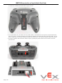
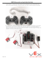
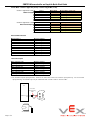
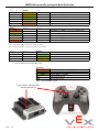
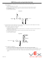
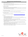
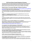
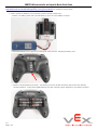
CORTEX Microcontroller and Joystick Quick Start Guide
This is a Quick Start Guide for using the VEX CORTEX Microcontroller and VEX Joystick. Refer to the VEX Wiki
(http://www.vexforum.com/wiki/index.php/VEX_Cortex_Microcontroller) for updates to this document.
1. Basic connections; batteries, microcontroller, joysticks and (2) VEXnet keys.
a. Attach 7.2v battery power and a VEXnet 802.11g key to the VEX CORTEX as shown.
b. Add AAA batteries to the Joystick by loosening the screw as shown. Remove the battery cover.
c. Install six identical batteries as shown. Use Alkaline, Ni-Cad or Ni-MH chemistries, but DO NOT mix different
chemistry batteries. Charge rechargeable batteries only with a quality charger designed for your battery chemistry.
0510
Page 1 of 9
CORTEX Microcontroller and Joystick Quick Start Guide
d. Reinstall the battery cover (insert the two tabs of the battery cover first along the back edge of the battery cover to aid
in installation) and add the VEXnet 802.11g key as shown.
e. For longest battery life, turn ON the units only when needed. Fresh batteries in the Joystick will provide about two
hours of run time. If wireless operation is not required, substitute the VEXnet keys with a USB A-A cable. For this
tether configuration, turn ON the CORTEX but leave the Joystick OFF. The USB A-A cable will power the Joystick.
f. Turn ON the CORTEX Microcontroller and the Joystick by setting the power switches to ON as shown in the two
pictures below.
Page 2 of 9
CORTEX Microcontroller and Joystick Quick Start Guide
g. A valid link is as shown. The VEXnet light will be blinking a fast green on both units. The Robot light will wink green
(be mostly on) on both units and when using fully charged batteries. It will take about 10 to 15 seconds for a link to
be established. The Joystick light will be solid green when using fully charged batteries.
h. If the units fail to link up, turn them both OFF and back ON. If they still fail to link up, tethering may be required.
Refer to the Tethering document for tethering instructions.
2. Basic Configuration
A few examples of the Default Code that is pre-programmed into the Cortex Microcontroller are shown below. For
complete details on the Default Code, refer to Section 3.
a.Add motors and test. The following picture shows 276-2163 VEX Motors plugged into Motor Port 2 and Motor Port
5. With default code, pushing Joystick Channel 3 up will cause Motor 2 to turn clockwise. Pushing Joystick Channel
2 up will cause Motor 5 to turn counterclockwise.
3
2
b.Motor Reversing: The default code allows jumpers or switches to be installed in the Digital Ports to invert the motor
direction. This is useful to correct the direction of motors without changing code, or when using a switch to reverse a
motor if the robot hits an object. The following picture shows motor reversing jumpers installed in Digital Ports 2 and
5 to reverse Motor Ports 2 and 5.
Page 3 of 9
CORTEX Microcontroller and Joystick Quick Start Guide
c. Two Joystick Operation: The default code allows two Joysticks to control motors when a jumper is installed in CORTEX
location Digital 11. Connect the two Joysticks together using the PARTNER Ports with a coiled handset cord as
shown. Only one Joystick should have a VEXnet key installed. The Joystick to Joystick connection is shown below.
d.Limit Switch Inputs: The default code allows jumpers or switches to be installed in the Analog Ports to limit certain
motor directions. These are useful for stopping a motor when an arm bottoms out. A limit switch plugged in to
Analog 1 will stop Motor 6 from turning counterclockwise when activated. A limit switch plugged in to Analog 2 will
stop Motor 6 from turning clockwise when activated.
Page 4 of 9
CORTEX Microcontroller and Joystick Quick Start Guide
3. Default Operation: Refer to the attached figures for details and options of Joystick input to Motor response. These motor
directions will make a Protobot robot go forward when the sticks are pushed “up”. Robots that do not have an idler
gear will go in the opposite direction until a reversing jumper is installed or custom code is created. Note the Jumper
variations for each section.
Page 5 of 9
CORTEX Microcontroller and Joystick Quick Start Guide
Arcade Mode - Channel 1 (right stick, X-axis) + Channel 2 (right stick, Y-axis)
Channel 1 (right stick, X-axis)
Robot Turn Rate
Motor 1
Motor 2
Motor 3
Motor 4
Motor 5
Motor 10
LEFT DRIVE
LEFT DRIVE
LEFT DRIVE
RIGHT DRIVE
RIGHT DRIVE
RIGHT DRIVE
Joystick Right = Motor CW
Joystick Right = Motor CW
Joystick Right = Motor CW
Joystick Right = Motor CW
Joystick Right = Motor CW
Joystick Right = Motor CW
Channel 2 (right stick, Y-axis)
Robot Forward Speed
Motor 1
Motor 2
Motor 3
Motor 4
Motor 5
Motor 10
LEFT DRIVE
LEFT DRIVE
LEFT DRIVE
RIGHT DRIVE
RIGHT DRIVE
RIGHT DRIVE
Joystick Up = Motor CW
Joystick Up = Motor CW
Joystick Up = Motor CW
Joystick Up = Motor CCW
Joystick Up = Motor CCW
Joystick Up = Motor CCW
Reverse Motor Direction
Reverse Motor 1
Reverse Motor 2
Reverse Motor 3
Reverse Motor 4
Reverse Motor 5
Reverse Motor 6
Reverse Motor 7
Reverse Motor 8
Reverse Motor 9
Reverse Motor 10
Jumper in Digital 1
Jumper in Digital 2
Jumper in Digital 3
Jumper in Digital 4
Jumper in Digital 5
Jumper in Digital 6
Jumper in Digital 7
Jumper in Digital 8
Jumper in Digital 9
Jumper in Digital 10
Limit Switch Inputs
Motor 6 ignores CCW
Motor 6 ignores CW
Motor 7 ignores CCW
Motor 7 ignores CW
Motor 8 ignores CCW
Motor 8 ignores CW
Motor 9 ignores CCW
Motor 9 ignores CW
Jumper in Analog 1
Jumper in Analog 2
Jumper in Analog 3
Jumper in Analog 4
Jumper in Analog 5
Jumper in Analog 6
Jumper in Analog 7
Jumper in Analog 8
a. The CORTEX may be reprogrammed. Shown is the interconnect sketch for wireless reprogramming. For non-wireless
reprogramming, the VEXnet keys may be substituted with a USB A-male to A-male cable.
PC
276-2186
Programming
Cable
USB Port
Program
Port
Microcontroller
Page 6 of 9
Joystick
CORTEX Microcontroller and Joystick Quick Start Guide
4. Diagnostics Information: refer to the following chart for Joystick and CORTEX light patterns and meanings.
Robot
Robot [1]
(red)
VEXnet
Blip (yellow)
Fast (yellow)
Fast (green)
Slow (yellow)
Solid (green)
Slow (red)
Game
VEXnet
Game
Startup - looking for USB device
Linking - Searching for VEXnet mate
Linked
Linked - Data quality reduced
Tethered
Fault: Lost Link - Searching for VEXnet mate
Main Battery = Dead (<5.5v) or CORTEX Off [2]
Main Battery = Low (<6.5v) [2]
Main Battery = Good
All Good: Both Joysticks connected
All Good: Tx1 Joystick connected
Fault: Low Backup Battery (0v-8v)
(yellow)
(green)
Solid
Solid + 1 Blink
Fast (red) [3]
Note 1: Robot LED only works on Joystick when Linked
Note 2: Lowest CORTEX battery color latched at Joystick and CORTEX
Note 3: No Backup Battery only indicated if competition cable is connected.
Robot
VEXnet
Game [4]
Off
Solid (green)
Fast (green)
Fast (yellow)
Note 4 : Game LED only used when the competition cable is connected.
No Competition connection
Driver
Autonomous
Disabled
Game LED only works on the Robot when Linked.
Joystick [5]
(red)
(yellow)
Fast
Solid
(green)
Joystick Battery = Dead (<5.5v)
Joystick Battery = Low (<6.5v)
Joystick Battery = Good
Two Joysticks in use
One Joystick in use
Note 5 : Joystick LED only on Joystick.
Robot, VEXnet, and Game LED’s
show the same data [2]
Page 7 of 9
CORTEX Microcontroller and Joystick Quick Start Guide
5. Analog Information: Analog lines are input only and read about 62 (0.2 volts) when open. When connected to a 0 to 5v
source, such as the VEX Potentiometer, you will read from near 0 (0 volts) to near 1023 (5 volts).
a. Circuit details:
i.Analog input range is 0 to +5 volts.
ii.Analog circuit has a 470k pull-up to +5 volts, a series 10k resistor and a 20k resistor to ground.
iii.Analog inputs also have a 1000 pF capacitor to ground on the processor side of the 10k resistor.
iv.3 dB bandwidth: 16 kHz.
v.Circuit connections as shown.
Analog Port
+5 V
470 K
10 K
Analog Input
(Typical)
To Processor
1000 PF
20K
6. Digital Information: When configured as an input, digital lines have a weak pull-up. When configured as an output,
digital lines drive 0 volts for a low and 3.3 volts for a high.
a. Circuit details, Digital Ports 1 through 12:
i.Digital input range is 0 to +5 volts.
ii.Digital drive is primarily limited by the 1k series resistor, so it can output a 2v high into 2k-ohms to ground or a
0.8v low into 7k-ohms to 3.3v.
iii.Digital inputs also have a 1000 pF capacitor to ground on the processor side of the 1k resistor.
iv.3 dB input bandwidth: 16 kHz.
v.Circuit connections as shown.
Digital Port
3.3 V
Weak Pull-up
In Processor
1K
Digital Input Output
1000 PF
b. Circuit details, SP Digital Port
i.Circuit SP is connected to the Digital-to-Analog-Converter (DAC) output of the User Processor.
ii.Factory default Hex file does not support the DAC output. Check your compiler for availability and use.
iii.SP is an Analog Output when configured by compiler. Drive is primarily limited by a 5 kilo-ohm internal processor
resistance and by the 100 ohm series resistor. Output swing of the processor into an open load is 0.2v to 3.1v,
typical.
Page 8 of 9
CORTEX Microcontroller and Joystick Quick Start Guide
7. 2-Wire Motor Port outputs:
a. Motor Port 1 and Motor Port 10.
b. Maximum motor stall current: 3.0 amps at 8.5 volts.
c. Motor chop rate: determined by the compiler. Default code chop rate: 1 kHz.
d. Overcurrent protection: Motor Port 1 through Motor Port 5 shares one 4 amp circuit breaker. Motor Port 6 through
Motor Port 10 shares a second 4 amp circuit breaker.
8. 3-Wire Motor Port outputs:
a. Motor Ports 2 through 9.
b. Maximum motor stall current: internally limited by motor assembly.
c. Motor PWM output: determined by the compiler. Default is 1 to 2 milliseconds high time and a 17 millisecond period.
d. Overcurrent protection: Motor Port 1 through Motor Port 5 shares one 4 amp circuit breaker. Motor Port 6 through
Motor Port 10 shares a second 4 amp circuit breaker.
9. UART Connections: Ground, Power (+5v), RX data in, TX data out. Data rate, byte width, (transmit) stop bits, parity,
etc. are determined by the compiler.
a. Default for LCD data: 19,200 baud, 8 data bits, 1 stop bit, no parity and no flow control.
10. I2C Connections: Ground, Power (+5v), Clock, Data. Data rate, byte width, (transmit) stop bits, parity, etc. are
determined by the compiler.
a. The factory default Hex file does not support I2C.
11. Joystick Calibration (optional): Refer to the VEX Wiki (http://www.vexforum.com/wiki/index.php/VEXnet_Joystick).
12. Debugging:
a.Slow blinking green Robot light on CORTEX.
Solution: Try VEXnet Upgrade Utility. If Master Code 4 or earlier, call or e-mail in to VEX Robotics.
b.Slow blinking Robot green light on Joystick.
Solution: Push and hold config button about 5 seconds until light starts flashing green. Release, wait about 5 seconds,
then turn Joystick OFF and then back ON.
c,Yellow or Red Robot light on the CORTEX. Solution: used fully charged Robot battery.
d. Yellow or Red Robot light on the Joystick, even though the CORTEX is green. Solution: Joystick latches CORTEX’s
lowest battery level. Power cycle both Joystick and CORTEX.
e. Fast red blinking Robot light when plugged in to a competition field. Solution: Use a fully charged 9v back-up battery
plugged in to the CORTEX.
f. Robot does not shut off when turned OFF. Solution: At the end of the match, remove the Ethernet cable from the
Competition Port of the Joystick. The CORTEX and Joystick will change to non-competition mode. Power off the
Joystick and CORTEX. The CORTEX will shut off in about 5 seconds.
g. Robot does not do what you want it to do. Solution: Download the default code and test to isolate hardware problems.
Then make small program changes testing after each change.
h. Robot still does not link up, even after tethering. Solution: Debug using a friends system to narrow down the problem,
check the VEX Forum or contact VEX Robotics for assistance.
Page 9 of 9