1
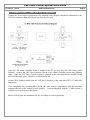
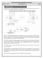
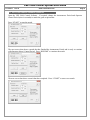
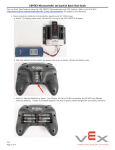
VEX Field Control System User Guide
11.13.2013
Rev B
www.vexrobotics.com
VEX Robotics, Inc.
VEX Field Control System
User Guide
Page 1
VEX Field Control System User Guide
11.13.2013
Rev B
www.vexrobotics.com
Page 2
Table of Contents
1.
2.
3.
4.
5.
6.
7.
8.
9.
10.
11.
VEX Field Control System Overview..................................................................................... 2
Software Installation ............................................................................................................... 2
Equipment Setup – VEXnet only Configuration .................................................................... 3
Equipment Setup – 75MHz VEX only Configuration ............................................................ 4
Equipment Setup – combined VEXnet and 75 MHz VEX Configuration .............................. 5
VEX Field Control Software Operation .................................................................................. 6
Theory of Operation ................................................................................................................ 7
Normal Operation.................................................................................................................... 8
Debugging – General .............................................................................................................. 9
Debugging – VEXnet robots ................................................................................................... 9
Debugging – 75 MHz robots ................................................................................................... 9
1. VEX Field Control System Overview
The VEX Field Control System is used to control multiple VEX teams during a match at a competition
or scrimmage. It can control both 75 MHz transmitters and VEXnet transmitters (Joysticks) in any
combination.
2. Software Installation
DO NOT attach the Match Controller Board to the PC unless you have first installed the VEX Field
Control Software and USB Driver per the Installation documentation. Currently the software is written
for PC compatible machines running Microsoft Windows: XP, Vista, and Windows 7 operating
systems.
VEX Field Control System User Guide
11.13.2013
Rev B
www.vexrobotics.com
Page 3
3. Equipment Setup – VEXnet only Configuration
Connect the Field Control equipment per the attached block diagram. Maximum connections to the
VEX Driver Interface Board are shown, not all need to be used.
After the VEX Match Controller Board is attached to the PC you may open the VEX Field Control
Software. Connect the VEX Driver Interface Boards to the Match Controller Board using Ethernet
cables. When the VEX Driver Interface Board is plugged in, the associated Match Controller Board
LED will illuminate green. Otherwise it will illuminate red.
Connect Ethernet cables from the associated VEX Driver Interface to the VEXnet transmitter
(Joysticks) COMPETITION ports. A second transmitter may be connected to the primary transmitter
using a 4-wire-4-contact (4P4C) handset cable. Only the primary VEXnet transmitter can have a
VEXnet Key installed.
If the competition has an autonomous period, the robot must be programmed with the associated
template/software for the control to work properly. To prevent frequency interference, all WIFI on
Channel 1 must be turned OFF.
Refer to official game documentation for any over-riding or extra requirements.
VEX Field Control System User Guide
11.13.2013
Rev B
www.vexrobotics.com
Page 4
4. Equipment Setup – 75MHz VEX only Configuration
Connect the Field Control equipment per the attached block diagram. Maximum connections to the
VEX Driver Interface Board are shown, not all need to be used.
After the VEX Match Controller Board is attached to the PC you may open the VEX Field Control
Software. Connect the VEX Driver Interface Boards to the Match Controller Board using Ethernet
cables. When the VEX Driver Interface Board is plugged in, the associated Match Controller Board
LED will illuminate green. Otherwise it will illuminate red.
Connect 4P4C handset cables from the VEX Driver Interface to the associated VEX (75 MHz) FM
transmitters.
If the competition has an autonomous period, the robot must be programmed with the associated
template/software for the control to work properly. Crystal management with the 75 MHz system is
required to prevent frequency interference.
Refer to official game documentation for any over-riding or extra requirements.
VEX Field Control System User Guide
11.13.2013
Rev B
www.vexrobotics.com
Page 5
5. Equipment Setup – combined VEXnet and 75 MHz
VEX Configuration
Connect the Field Control equipment per the attached block diagram. Maximum connections to the
VEX Driver Interface Board are shown, not all need to be used.
After the VEX Match Controller Board is attached to the PC you may open the VEX Field Control
Software. Connect the VEX Driver Interface Boards to the Match Controller Board using Ethernet
cables. When the VEX Driver Interface Board is plugged in, the associated Match Controller Board
LED will illuminate green. Otherwise it will illuminate red.
For VEXnet transmitters (Joysticks), connect an Ethernet cable from the associated VEX Driver
Interface to the transmitter COMPETITION Port. A second transmitter may be connected to the
primary transmitter using a 4-wire-4-contact (4P4C) handset cable. Only the primary VEXnet
transmitter can have a VEXnet Key installed.
For 75 MHz transmitters, connect 4P4C handset cables from the VEX Driver Interface to the associated
VEX FM transmitters.
If the competition has an autonomous period, the robot must be programmed with the associated
template/software. 75 MHz and VEXnet systems can be used concurrently. To prevent frequency
interference, crystal management with the 75 MHz system is required and all WIFI on Channel 1 must
be turned OFF.
Refer to official game documentation for any over-riding or extra requirements.
VEX Field Control System User Guide
11.13.2013
Rev B
www.vexrobotics.com
Page 6
6. VEX Field Control Software Operation
Open the VEX Field Control Software. If required, change the Autonomous Period and Operator
Control Period (time in seconds) to match the game requirements.
Press “START” to start the match.
The next screen shot shows a match that has finished the Autonomous Period and is ready to continue
with Operator (driver) Control Period. Press “RESUME” to continue the match.
The next screen shot shows a match that has completed. Press “START” to start a new match.
VEX Field Control System User Guide
11.13.2013
Rev B
www.vexrobotics.com
Page 7
7. Theory of Operation
The VEX Field Control System typically sequences through the game in five states; Disabled,
Autonomous Period, Disabled (for autonomous scoring), Driver Control Period, and Disabled (end of
match).
The 75 MHz VEX robots must have a special software template to allow for this sequencing. The
software template will put the VEX robots into autonomous mode for the first xx seconds after
powering ON and a valid transmitter output is received. The value xx is determined by the game
requirement. After xx seconds has elapsed, the VEX robot software automatically goes into driver
control mode. The VEX Field Control Software turns on the 75 MHz VEX transmitter outputs during
the Autonomous and Driver Control times. It disables the VEX transmitter outputs at all other times.
Note that once autonomous starts, the robot does not receive the transmitter output until the autonomous
template has finished. This means that robots running in autonomous can not be stopped by the Field
Control System.
The VEXnet robots accept an Autonomous/Driver Signal and an Enable/Disable Signal from the VEX
Field Control System. They do require a special competition template for proper operation of the
Autonomous and Driver Modes , but they do not need special templates to determine the run time of the
Autonomous Mode like the 75 MHz VEX robots. The VEXnet robots can be halted by the VEX Field
Control System at any time.
VEX Field Control System User Guide
11.13.2013
Rev B
www.vexrobotics.com
Page 8
8. Normal Operation
Verify all robots are TURNED OFF.
Verify all transmitters are TURNED OFF.
Connect the VEX transmitters to the Driver Interface Boards with the provided cables.
Verify the VEX Field Control Software Timer is not running, or click STOP to turn OFF the timer.
TURN ON all robots. Place them in the starting position and configuration.
TURN ON all transmitters. If a robot moves, verify the 4P4C handset cable or Ethernet cable is
properly attached to the transmitter.
VEXnet NOTE: It does not matter whether the robot (Cortex) or VEXnet transmitter (Joystick) is
turned ON first. However, it saves “Link Time” if the VEXnet transmitter (Joystick) is connected to
the Driver Interface Board before being turned ON.
Click on “START” on the VEX Field Control Software to start the game.
Click on “RESUME” on the VEX Field Control Software to resume the game after the Autonomous
Period.
The software will Auto Reset at the end of the Driver Period and it will be ready for the next match.
Disconnect all transmitters from the Driver Interface Boards.
TURN OFF all transmitters.
TURN OFF all robots.
VEXnet NOTE: The VEXnet transmitter (Joystick) must be disconnected from the Driver Interface
Board first and then turned OFF. This will allow the robot (Cortex) to turn OFF 3-5 seconds after its
Power Switch is turned OFF. Otherwise, the robot (Cortex) will continue to stay ON using Back-up
Battery Power if available.
VEX Field Control System User Guide
11.13.2013
Rev B
www.vexrobotics.com
Page 9
9. Debugging – General
Verify that the transmitter and robot batteries are fully charged.
Close the VEX Field Control Software and reopen it if you have disconnected/reconnected the USB
cable or if you started the software before connecting the VEX Match Controller Board to the PC.
Make sure that no interfering tasks are running, such as the VEX Tournament Manager Software.
10. Debugging – VEXnet robots
First, disconnect the VEXnet transmitter (Joystick) from the VEX Driver Interface. Turn on the robot
and transmitter. Verify they link up by flashing green VEXnet lights on both the robot and transmitter.
If not, perform the “Pairing” operation with a USB-A to USB-A cable between the robot and
transmitter. Then connect the VEXnet transmitter competition port to the VEX Driver Interface using
an Ethernet cable. The Robot and Transmitter GAME lights will show the state of the game: blinking
yellow for Disabled, blinking green for Autonomous and solid green for Driver mode. If the ROBOT
light is blinking fast red, a charged backup battery needs to be attached. The no-backup-battery
indication is not displayed if the transmitter is not attached to a VEX Driver Interface Board via the
COMPETITION Port.
If robot action is erratic:
Verify that the transmitter and robot batteries are fully charged.
Verify the transmitter and robot will link together if not attached via the VEX Field Control System.
11. Debugging – 75 MHz robots
To check for a valid Autonomous / Driver Mode Template in the 75 MHz VEX robots, start with the
robot turned OFF. Do not connect the VEX transmitter to the Driver Interface Board. Turn on the VEX
(75MHz) transmitter. Turn on the Robot. Try to drive the robot within the first xx seconds. If it moves
via your transmitter instructions, then the template has not been programmed into the VEX
microcontroller. Reprogram the robot with the valid template.
If robot action is erratic
Verify that the transmitter and robot batteries are fully charged.
Verify that no two transmitters or receivers have the same crystal frequency.
Verify the transmitter and respective receiver have the same crystal frequency.
Verify that the competition crystals are being used and that proper channel spacing is being used.
(Someone in the pits may be using the default or Set A or Set B crystals.)
Verify that the (75 MHz) transmitter and receiver antennas are fully extended.
Appendix A: Document Version History
Date Code
Changes
2009-08-14
Initial document release.
Nov 30, 2011
Rev A - Corrected various areas and changed board names.
Nov 13, 2013
Rev B - Added VEXnet notes in Section 8.