1
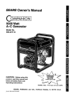
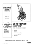
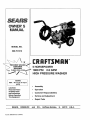
OWNER'S
MANUAL
MODEL NO.
580.751510
®
5 HORSEPOWER
1800 PSi 2.5 GPM
HiGH PRESSURE WASHER
HOURS:
Mort.- Fri. 8 a.m. to 5 p.m
(CST)
CAUTION:
Read and Follow
all Safety Rules
and Instructions
Before Operating
This Equipment
SEARS,
ROEBUCK
Part No 96596 Revision 3 (6/20195)
o
Assembly
o
Operation
°
Customer
o
Service and Adjustment
°
Repair Parts
and
CO.,
Responsibilities
Hoffman
Estates,
IL
60179
U.S.A.
SAFETY
_
TACT SPARK PLUG, TO PREVENT ACCIDENTAL STARTING WHEN SETTING UP, TRANSPORTING,
AUTION: ALWAYS DISCONNECT SPARK PLUG WIRE AND PLACE WIRE WHERE IT CANNOT CON_ _,
ADJUSTING OR MAKING REPAIRS TO YOUR HIGH PRESSURE WASHER.
TRAINING:
e Engine exhaust gasescontain DEADLY carbon monoxIde gas_ This dangerous gas, if breathed in sufficient
concentrations,can cause unconsciousness or even
death. Operate this equipment onlyin the open airwhere
adequate ventilation is available.
® Gasoline is highly FLAMMABLE and its vapors are EXPLOSIVE. Do not permit smoking, open flames, sparks
or heat in the vicinity while handling gasoline° Avoid
spilling gasoline on a hot engtne_Allow unit to coolfor 2
minutes before refueling. Comply with all laws regulating
storage and handling of gasoline°
•
Locate this pressure washer in areas away from combustible materials, combustible fumes or dust.
•
The high pressure equipment is designed to be used with
Sears authorized parts onlyo If you use this equipment
withpartsthatdonotcomplywithminimumspecifications,
the user assumes all risksand liabilities°
e Some chemicalsor detergentsmay be harmful if inhaled
or ingested,causingseverenausea,fainting or poisoning
The harmfu!elements may cause propertydamage or
severe injury_
•
Do notallowCHILDREN tooperatethe PressureWasher
at any time_
PREPARATION:
e Operate engine only at governedspeed Runningthe
engine at excessive speeds increases the hazard of
personalinjury° Do not tamper with parts which may
increaseor decrease the governedspeed.
o Do not wear looseclothing,jewelryor anything that may
be caughtin the starteror otherrotating parts.
•
Before startingthe PressureWasher in cold weather,
checkall partsof the equipment and be sure ice has not
formed there.
e Unitswith broken or missing parts,or withoutprotective
housingor coversshouldNEVER be operated°
= The mufflerand air cleanermust be installedand in good
condtflonbefore operatingthe PressureWasher. These
componentsact as sparkarrestorsif theenginebackfires
e Check the fuel systemfor leaksor signsof deterioration
suchas chafedor spongy hose, loose or missingclamps
or damagedtank or cap. Correctall defects before operatingthe Pressure Washer.
OPERATION:
•
,,
=
=
•
RULES
Do not spray flammableliquids.
Never aim the gun at people,animals or plants.
Never allow any part of the bodyto come incontactwith
the fluid stream. DO NOT come in contactwith a fluid
streamcreated by a leak in the high pressurehose
High pressure stream of fluid that this equipment can
producecan piema skinand itsunderlyingtissues,leading to sedous injuryand possibleamputation
High pressurespraycan cause paintchipsor other particlesto become airborneand fly at high speeds=
•
Always wear eye protection when you use this equipment
or when you are in the vicinity where the equipment is in
use.
e
Operate the pressure at no more than the PSI fluid
pressure rated for your pressure washer.
Never move the machine by pulling on the high pressure
hose. Use the handle provided on the top of the uniL
Always be certain the spray gun, nozzles and accessories
are correctly attached.
Never use a spray gun which does not have a trigger lock
or trigger guard in place and in working order:
Use a respirator or mask whenever there is a chance that
vapors may be inhaled. Read al! instructions with the
mask so you are certain the mask will provide the necessary protection against inhaling harmful vapors
High pressure spray may damage fragile items including
glass Do not point spray gun at glass when in the jet
spray mode
Keep the hose connected to machine or the spray gun
while the system is pressurized Disconnecting the hose
while the unit is pressurized is dangerous°
Hold the spray gun firmly in your hand before you start
the unit, Failure to do so could result in an injury from a
whipping spray gun Do not leave the spray gun unattended while the machine is running.
•
=
®
®
o
e
o
,D
The cleaning area should have adequate slopes and
drainage to reduce the possibility of a fall due to slippery
surfaces.,
e
Keep waterspray away from electric wiring or fatal electdc
shock may resulL
e
=
Do not adjust unloader valve to a pressure in excess of
machine rating_
Do not secure trigger gun in the pull-back (open) position.
=
Do not by-pass any safety device on this machine
o
Do not leave tngger closed for more than 5 minutes with
engine running This could damage the pump.
The muffler and engine heat up during operation and
remain hot immediately after shutting it down. Avoid
contact with a hot muffler or engine or you could be
severefy bumed
=
MAINTENANCE
AND STORAGE:
e
Operate and store this unit on a stable sudace,
=,
High pressure hose can develop leaks from wear, kinking,
abuse, etc, Water spraying from a leak is capable of
injecting material into skin, Inspect hose each time before
using it. Check all hoses for cuts, leaks, abrasions ol
bulging of cover, or damage or movement of couplings. If
any of these conditions exist, replace hose immediately.
Never repair high pressure hose Replace it with another
hose that meets minimum pressure rating of your pros=
sure washer
SAFETY
PRECAUTIONS.
MEANS
BELOOK FOR
THIS SYMBOL IT TO
POINT "ATTENTION!It
OUT IMPORTANT
COME ALERTH!
YOUR SAFETY IS INVOLVED."
i
CONGRATULATIONS on your purchase of a Sears Craftsman high pressure washer, it has been designed, engineered and manufactured to give you the best possible
dependability and performance.
Should you experience any problem you cannot easily
remedy, please contact your nearest Sears Service Center/Department or call the 1-800 number listed on the front
of this manual We have competent, well*trained technicians and the proper tools to service or repair this uniL
Please read and retain this manual° The instructions will
enable you to assemble and maintain your high pressure
washer properly. Always observe the "SAFETY RULES."
MODEL
NUMBER
580,751510
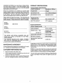
PRODUCT
SPECIFICATIONS
Pressure Washer Specifications
PUMP PRESSURE
Adjustable to 1800 psi .......
FLOW RATE
2.5 gpm
DETERGENT
MIX
Use undiluted detergent
DETERGENT
RATIO
Adjustable to 66:1
WATER SUPPLY
TEMPERATURE
Not to exceed 140°F
SUCTION HEIGHT
3 FT° maximum
Engine Specifications
SERIAL
RATED HORSEPOWER
5
NUMBER
DISPLACEMENT
12,6 cu. inches
SPARK PLUG:
DATE OF
PURCHASE
Type:
Set Gap To.
GASOLINE CAPACITY
THE MODEL AND SERIAL NUMBERS WILL BE
FOUND ON A DECAL ATTACHED TO THE PRESSURE WASHER,
YOU SHOULD RECORD BOTH SERIAL NUMBER
AND DATE OF PURCHASE AND KEEP IN A SAFE
PLACE FOR FUTURE REFERENCE.
MAINTENANCE
AGREEMENT
A Sears Maintenance Agreement is available on this product, Contact your nearest Sears store for details,
CUSTOMER
RESPONSIBILITIES
=
Read and observe the safety rules,
=
Follow regular schedule in maintaining, caring for and
using your high pressure washer,
•
Follow the instructions under "Customer Responsibilities" and "Storage" sections of this Owner's Manual,,
OIL (20 oz. capacity)
Champion RCJ8
or equivalent
0.030 inch (0,76mm)
.....
2 U.S. quarts
..........
SOLID STATE IGNITION
AIR GAP
SAE 30 weight
0o0125 inch
in the State of California a spark arrestor is required by law
(Section 4442 of the California Public Resources Code),
Other states may have similar laws. Federal laws apply on
federal lands,
NOTE: If you equip the engine of your pressure washer with
a spark arrestor muffler, the spark arrestor must be maintained in effective working order by the owner operator.
You can order a spark arrestor through your Sears Service
Center, See Repair Parts section of engine for part numbers,
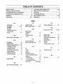
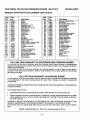
TABLE OF CONTENTS
SAFETY RULES .............................................................
2
CUSTOMER
PRODUCT SPECIFICATIONS
.......................................
3
SERVICE AND ADJUSTMENTS
AND ATTACHMENTS .........................
5
STORAGE ....................................................................
6
TROUBLESHOOTING
ACCESSORIES
CONTENTS OF HARDWARE PACK .............................
ASSEMBLY ..................................................................
7-8
OPERATION ..............................................................
9-13
RESPONSIBILITIES
REPLACEMENT
WARRANTY
..........................
14-15
..................................
...................................................
PARTS .........................................
16
17
18
t 9-27
.................................................................
25
INDEX
-AAccessories ..............
Air Cleaner .............
Assembly
Checklist ....................
Removingfrom Carton .........
Tools Required...............
Set Up ..........................
H
5
9,15
-p-
Hardware Pack ............
High Pressure Hose .......
6
7
7
7-8
-M-
Replacement
Agreement ......................
Engine ....................
Pressure Washer ...............
Pump .....................
3
15
14
16
N
-C16
Cleaning Tips ............
13
Customer Responsibilities _ 3,14
Changing Otl, engine ...........
t5
Changing Oil, pump ............
16
Checking Oil Level ...............
15
General Recommendations .... 14
Pressure Washer ............
14
ReplaceSpark Plug ............
15
ServiceAir Cleaner...........
15
-E16
Parts ......
19-29
Maintenance
Before Starting the Engine =. 11
Engine Speed .............
10
-R8
-B-
Carburetor ...............
PressureRegulator........
8, 9
Nozzle, Adjustable .........
Nozzle, Optional Turbo .......
10
11
-SSafety Latch .............
Safety Rules ..............
Service and Adjustments...
Siphoning ................
Specifications .............
Storage
Engine....................
Pressure Washer Pump ......
13
2
16
13
3
17
17
-O-T-
O_1
Engine ....................
Pump .......................
Operation
Detergent Application ........
Know Your Pressure Washer ....
12
16
11
9
Stopping ..........................
10
To Start Engine .............
13
To Turn on Washer ...........
12
Using Adjustable Nozzle .......
10
Order Parts .......
back page
-GGun and Wand Assembly o. 8, 9
4
Troubleshooting
..........
18
-WWarranty ................
25
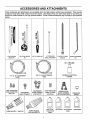
ACCESSORIES AND ATTACHMENTS
These accessories and attachments were available when the high pressure washer was purchased. They are also
available at most Sears retail outlets and service centers, Most Sears stores can order these items for you when you
provide the model number of your high pressure washer, Some of these accessories may not apply to your pressure
washer°
i
!=
i
i
FLOOR/SIDING
BRUSH KIT
ROTATING BRUSH
KIT
,
,
UTILITY BRUSH KIT
, ...............
18" STAINLESS
STEEL EXTENSION
,
,,
,
ELECTRIC TURBO
NOZZLE
ANGLE EXTENSION
KIT
,
T
HIGH PRESSURE
HOSE QUICK CONNECT KIT
CHEMICAL INJECTION
FOAMER
3/8" I,D, 50 ft. EXTENSION
HOSE
1/4" I,D 25 ft. EXTENSION
HOSE
ACCESSORY
QUICK CONNECT
ACCESSORY
QUICK CONNECT
STARTER KIT
HIGH PRESSURE
HOSE TO HOSE
COUPLING
GARDEN HOSE
QUICK CONNECT
WITH 2 ADAPTORS
PRESSURE
GAUGE
I
L___..J
TURBO NOZZLE - 1800 PSI
TURBO NOZZLE
2200 and 2500 PSI
MULTI-PUR*
POSE/HOUSE
WASH
DECK WASH
VEHICLE/BOAT
WASH
DEGREASER
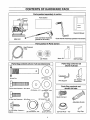
CONTENTS
OF HARDWARE
Parts packed
separately
PACK
in carton
Parts Carton
l
Owners Manual
,_r.__f
Main Unit
Gun and Wand Assembly
(packed in flat carton)
Parts packed
Guide Handle Assembly (packed in flat carton
in Parts Carton
High Pressure
Hose
Motor Oil
(2) Wheels
Parts Bag contents
shown full size (fasteners)
(3)Parts Bags
Parts Bag contents not
shown full size
(2) Washers - M8
(2) Axle Pins
(2) Support
Wire Support
Leg
Assemblies
Parts Bag contents not
shown full size
(2) Hex Head Capscrews - M8 x 40mm
(2) Washers - #10
(2) Washers
- M t2
©
Quick Connect
(6) Flange Nuts - M8
Adjustable Nozzle
U
(2) Self-drilling Capscrews
#10-16
(2) Lock Washers - 5/8"
(2) 5/8" JAM Nuts
(2) Push Nuts-
1/2"
Vinyl Cap
ASSEMBLY
Read these instructions and Operator's Manual in its entirety before you attempt to assemble or operate your new
high pressure washer. Your high pressure washer has, for
the most part, been assembled at the factory, except those
parts left unassembled. Before you can operate your new
high pressure washer, you must assemble the wheel kit and
properly connect the high pressure hose.
HOW
REQUIRED
•
Mallet
=
2 adjustable wrenches OR the following wrenches:
•
5/t6" (Smm) combination wrench
=
1/2" (13ram) combination wrench
=
5/8" (16mm) combination wrench
I1/16" (18ram) combination wrench
7/8" (22ram) combination wrench
=
I5/16" (24ram) combination wrench
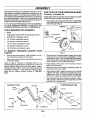
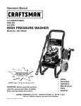
TO REMOVE
CARTON
JAM NUT
AXLE
•
=
PRESSURE
WASHER
Prop up the engine end of the main unit, This wilt allow
you to slip each axle pin into the holes provided on the
side of the base (Fig. 1).
FOR ASSEMBLY
,,
PRESSURE
Installing the wheel kit requires the tools listed, the guide
handle and items included in the parts carton.
IF YOU HAVE ANY PROBLEMS WITH THE ASSEMBLY
OF YOUR PRESSURE WASHER, PLEASE CALL THE
PRESSURE WASHER HELPLINE AT 1-800-222-3136,
TOOLS
TO SET UP YOUR
TO INSTALL THE WHEEL KIT
LOCKWASHER
JAM NUT
REVERSE ANGLE
FLAT WASHER
PUSH NUT
WASHER
WHEEL
FROM
FIG. 1
o
Remove two boxes marked "PARTS INSIDE" and remove the parts contained in both boxes.
,,
Remove unit with one hand under pump and one hand
under recoil starter.
Refer to Page 6, "Contents of Hardware Pack" for an
illustrated listing of all the items included with your pressure
washer. Become familiar with each piece before assembling the pressure washer. Check all contents against the
illustrations on Page 6. If any parts are missing or damaged, call the Pressure Washer Helpline at 1-800_2223136.
o
With the axle pin inserted inside the base, grip the end
of the axle pin as shown with an adjustable or 15/16
combination wrench. This will keep axle from spinning
as you fasten axle to the base with a 5/8" lock washer,
a 5/8"-18 JAM nut, and an M12 flat washer.
•
Place wheels on the axles so the rib side of hub is
against mounting base.
o
Retain each wheel to its axle pin by tapping a push nut
onto end of axle with a malleL
o
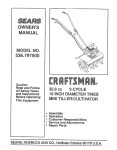
Attach support legs to base as shown in Fig. 2 with M8
x 20mm hex head capscrews and flange lock nuts.
Tighten with 13mm or lt2-inch wrench on each fastener. Be sure legs are straight when you are finished.
Attach the guide handle to the base as shown in Fig. 2
with two M8 x 40mm hex head capscrews, two M8
washers and two flange nuts_
Installing the Handle
Installing Support Legs
CAPSCREW
GUIDE
HE.XNUT
HANDLE
WASHER
WASHER
\
WiRE SUPPORT
CAPSCREW
CAPSCREW
FIG. 2
ASSEMBLY
=
Using a 5/16" (8mm) wrench, attach wire support to top
two holes of guide handle with #10 self-drilling screws
and #10 flat washers (Fig. 3), The hose minder should
be to the left and _unholder to the right° Be sure loop
of support is pointing upward. Place vinyl cap onto gun
holder.
connector. Reattach male connector to water inlet and
attach female connector to garden hose.
Q
WIRE SUPPORT
J
Unravel high pressure hose, remove plastic cap on end
of hose and check other end of |lose to see that threads
are properly covered with teflon tape. If tape is not
properly applied, reapply it so threads are fully covered.
The tape seals the connection from hose to gun and
wand assembly°
Attach fitting with teflon tape to gun and wand assembly
(Fig. 6). You may want to sp=n gun or spin hose to
secure connection. Tighten hose using 11/16" and 7/8"
wrenches.
VINYL CAP
FASTENERS
• !\
FIG. 3
FIG. 6
TO ASSEMBLE REMAINING COMPONENTS
IMPORTANT: YOU MUST ASSEMBLE WAND AND ATTACH ALL HOSES BEFORE YOU START ENGINE.
STARTING
ENGINE WITHOUT ALL HOSES CONNECTED AND WATER SUPPLIED WILL DAMAGE
PUMP.
,=
Attach the other end of the high pressure hose to high
pressure fitting on pump (Fig° 7)° Tighten with 15t16
(24mm) wrench.
I
.laHPR SSd
PUMP
j
DIPSTICK
Remove the red cap
from the oil fill hole on
thepump and insert Oil
Fill Cap (Fig. 4),
FIG. 4
Included with this unit is a Quick-Connect fitting you
attach to Water Inlet. The quick-connect includes two
parts -- a Male Connector factory-installed on water
infet and a Female Connector (Fig. 5). Remove male
connector to inspect Intake Supply Screen in water inlet
for cleanliness and inspect Inlet Screen on female
NLET
FEMALE
CONNECTOR
INLET SCREEN
FIG. 5
HIGH PRESSURE
HOSE
FIG. 7
o
To attach the adjustable
section, Fig_ 10,,
nozzle refer to Operation
CHECKLIST
°
Check that fasteners you used to install wheel kit and
handles are tighL Vibration during operation may
loosen fasteners that are not tight enough.
•
Check for proper hose connections (high pressure and
water supply) and for tight connections and that there
are no kinks, cuts, or damage to high pressure hose.
•
Provide proper water supply (not to exceed t40°F)o
o
Be sure to read "Safety Rules" and "Operation"
tions before using the pressure washer.
sec-
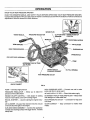
OPERATION
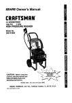
KNOW YOLIR HIGH PRESSURE WASHER
READ THIS OWNER'S MANUAL AND SAFETY RULES BEFORE OPERATING YOUR HIGH PRESSURE WASHER.
Compare the illustrations with your high pressure washer to familiarize yourself with the locations of various controls and
adjustment& Save this manual for future reference.
SPARK PLUG
GUIDE HANDLE
PRESSURE REGULATOR
CUP FOR WAND
STORAGE
ENGINE RUN/STOP
CONTROL
MUFFLER
NOZZLE
WIRE SUPPORT
]CLEANER
HIGH PRESSURE HOSE
CARBURETOR
GUN AND WAND ASSEMBL_
DETERGENTPICK UPTUBE
ANDFILTER
SPARE NOZZLE
STORAGE GROMMET
CONNECTOR
OIL FILL OPENING
HIGH PRESSURE OUTLET
MALE
INLET
:
QUICK CONNECT
FIG. 8
PUMP -- Develops high pressure°
PRESSURE REGULATOR -- Allows you to adjust the
pressure of the outlet stream
HIGH PRESSURE HOSE -- Connect one end to water
pump and other to spray wand.
INTAKE SUPPLY FILTER -- Filters inlet water supply,
ENGINE ON-OFF CONTROL -- Sets engine in starting
mode for recoil starter; turns OFF running engine,
DETERGENT PICKUP TUBE AND FILTER -- Mixes water
and detergent in outlet water flowo
RECOIL STARTER -ally,
HIGH PRESSURE OUTLET -- Connection for high pressure hose_
Used for starting the engine manu-
AIR CLEANER - Dry type filter element limits the amount
of dirt and dust that gets in the engine,
GUN AND WAND ASSEMBLY-- Controls the application
of water onto cleaning surface with trigger device. Includes
safety latch_
QUICK-CONNECT
supply°
--
Easy connection
for intake water
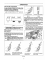
OPERATION
HOW TO USE YOUR WASHER
IF YOU HAVE ANY PROBLEMS OPERATING YOUR
PRESSURE WASHER. PLEASE CALL THE PRESSURE
WASHER HELPLINE AT 1-800-222-3136.
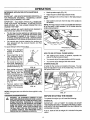
STOPPING YOUR PRESSURE WASHER
o
First, move engine throttle lever to"OFF" position (Fig.
9).
ADJUSTABLE NOZZLE
OPTIONAL TURBO NOZZLE
FIG. 10
I OFF,
IDLE
FAST
With the adjustable nozzle you can adjust the spray pattern
to be either high pressure or low pressure. You can also
adjust the spray so it is concentrated in a stream pattern or
expanded into a fan pattern. Use this nozzle to apply
detergent°
l
=
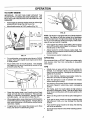
Push the nozzle attachment forward when you wish to
adjust the spray to low pressure mode (Fig, 12). Push
the nozzle backward to achieve high pressure.
•
Twisting the nozzle adjusts the spray pattern from a
narrow stream to an expanded stream,
•
You can also adjust the pressure by turning the pressure control knob (Fig, 13) to the desired pressure
setting. Turning this knob all the way clockwise produces the highest pressure Do not unscrew the pressure control valve more than 3 turns, tt will come off.
FIG. 9
o
FIG, U
Simply shutting OFF engine will not release pressure In the system. Pull the trigger on the spray wand
assembly to relieve the pressure in the hose.
NOTE: A small amount of water will squirt out when you
release the pressure.
SPRAY NOZZLES
PRESSURE
CONTROL
KNOB
Your high pressure washer comes equipped with an adjustable nozzle (Fig. t2)o Attach nozzle as shown in Fig. 10
and HAND TIGHTEN the plastic knob. Figure 12 shows the
optional turbo nozzle.
HOW TO USE ADJUSTABLE
A
NOZZLE
WARNING:
NEVER ADJUST SPRAY PATTERN
WHENSPRAYING.
NEVERPUTHANDSINFRONT
OF SPRAY NOZZLE TO ADJUST SPRAY PAT_
TERN.
NOZZLE IN HIGH
PRESSURE MODE
FIG. 13
PUSH NOZZLE FORWARD FOR
LOW PRESSURE MODE AND DETERGENT APPLICATION
TWIST NOZZLE TO
EXPAND SPRAY
FIG. 12
10
TWIST NOZZLE TO NARROW
SPRAY STEAM
OPERATION
DETERGENT APPUCATION
NOZZLE
WITH ADJUSTABLE
IMPORTANT: USE SOAPS DESIGNED SPECIFICALLY
FOR PRESSURE WASHERS.
HOUSEHOLD DETERGENTS COULD DAMAGE THE PUMP.
IMPORTANT:
YOU MUST ATTACH ALL HOSES BEFORE YOU START THE ENGINE. STARTING THE EN_
GINE WITHOUT ALL THE HOSES CONNECTED WILL
DAMAGE THE PUMP_
Pressure washers are useful cleaning tools designed to
clean almost any surface in two easy steps.
=
o
o
Hook up water supply (Fig° 16).
o
Adjust nozzle to select high pressure mode,
NOTE:
mode,
o
Detergent will not flow when in the high pressure
Start washer and work from the top of the surface to
the bottom_
NOTE: The high pressure mode is most effective when the
tip of the wand is held between 8 to 24 inches from the
surface being cleaned.
The first step involves applying an appropriate detergent/solvent solution to penetrate and loosen grime.
The detergent is applied at low pressure to avoid
splashing overspraying and waste. Leave the solution
on surface for 3 to 5 minutes to a ow so ution to work.
FEMALE CONNECTOR
The second step involves cleaning the surface you
have prepared with the pressure washer and then
rinsing it clean,
To apply detergent follow these steps:
•
o
o
WATER SUPPLY
Prepare your detergent
solution as required by
yourjobo
Place small filter of the
clear, detergent siphoning tube into the detergent container (Fig, 14)o
Set nozzle to low pressure mode, Detergent is
not siphoned in the high
pressure mode (Fig, 12)_
•
Start washer and apply
detergent to a dry surface. starting from the
bottom and working up.
You can adjust the concentration of detergent
by turning the knob on
the detergent
injector
(Fig, 15)_
o
Remove siphon from
bottle to stop flow of detergent in low pressure
mode,
FIG. 16
HOW TO USE OPTIONAL TURBO NOZZLE
=
The rotating turbo nozzle, in essence, expands the
area of the high pressure stream.
,,
You cannot adjust the spray pattern with this nozzle.
•
You cannot apply detergent with this nozzle.
STORING NOZZLES
FIG. 14
A holder for the nozzles is included on the base. You can
keep the adjustable nozzle in this holder (Fig, 17) or even
the optional turbo nozzle,
FIG, 15
OPT!ONAL TURBO NOZZLE
NOTE: Detergents are most effective when applied to a dry
surface.
PRESSURE
FIG. 17
WASHING/RINSING
WARNING:
BE EXTREMELY
IF YOU
MUST USE PRESSURE
WASHERCAREFUL
FROM LADDER,
SCAFFOLDING OR ANY OTHER RELATIVELY UNSTABLE LOCATION. PRESSURE IN A RUNNING
WASHER BUILDS IN THE WAND AS YOU CLIMB.
WHEN YOU PRESS THE TRIGGER, THE RECOIL
FROM THE INITIAL SPRAY COULD FORCE YOU
TO FALL, OR IF YOU ARE TOO CLOSE TO THE
CLEANING SURFACE, HIGH PRESSURE COULD
FORCE YOU OFF CLIMBING APPARATUS.
BEFORE
STARTING
THE
ENGINE
To operate the engine you will need the following:
ENGINE OIL
IMPORTANT:
ANY ATTEMPT TO CRANK OR START
THE ENGINE BEFORE IT HAS BEEN PROPERLY SERVICED WITH THE RECOMMENDED OIL MAY RESULT IN
AN ENGINE FAILURE,
A 27 oz. bottle of SAE 30 weight oil is included in the parts
carton,
11
OPERATION
GAS
NOTE: When adding oil to the engine crankcase in the
future, use only high quality detergent oil rated with API
service classification SF, SG or SH rated SAE 30 weight°
Use no special additives. Select the oil's viscosity grade
according to your expected operating temperature.
f
colder
32°F
5W30
_
WARNING: NEVER FILL FUEL TANK INDOORS.
NEVER RLL FUEL TANK WHEN ENGINE IS RUNNING OR HOT, DO NOT SMOKE WHEN FILLING
FUEL TANK.
WARNING:
NEVER
FILL FUEL TANK COMPLETELY FULL. FILL TANK TO ABOUT 1/2" BELOW THE BOTTOM OF FILLER NECK TO PROVIDE
SPACE FOR FUEL EXPANSION. WIPE AWAY ANY
FUEL SPILLAGE FROM ENGINE AND EQUIPMENT
BEFORE STARTING.
warmer
SAE30
Although multi-viscosity oils (5W30, 10W30, etc.) improve
starting in cold weather, these multi-viscosity oils will result
in increased oil consumption when used above 32°F.
Check your engine oil level more frequently to avoid possible damage from running low on oil. Oil sump capacity is
20 ounces.
•
Position pressure washer so engine is level.
o
Clean area around oil fill plug and remove oil fill plug
(Fig. 18).
The manufacturer recommends fresh, clean, unleaded
regular automotive gasoline with a minimum of 77 octane
(Leaded regular grade is an acceptable substitute). Tank
capacity is 2 UoS. quarts.
,=
Use clean fuel and store in approved, clean covered
containers. Use clean fill funnels. Never use "stale"
]oaSOlineleft over from last season or gasoline stored
r long periods.
IMPORTANT:
IT IS IMPORTANT TO PREVENT GUM
DEPOSITS FROM FORMING tN ESSENTIAL FUEL SYSTEM PARTS SUCH AS THE CARBURETOR, FUEL FILTER, FUEL HOSE OR TANK DURING STORAGE° ALSO,
EXPERIENCE INDICATES THAT ALCOHOL-BLENDED
FUELS (CALLED GASOHOL OR USING ETHANOL OR
METHANOL) CAN ATTRACT MOISTURE WHICH LEADS
TO SEPARATION AND FORMATION OF ACIDS DURING
STORAGE. ACIDIC GAS CAN DAMAGE THE FUEL SYSTEM OF AN ENGINE WHILE IN STORAGE. TO AVOID
ENGINE PROBLEMS, THE FUEL SYSTEM SHOULD BE
EMPTIED
BEFORE
STORAGE
OF 30 DAYS OR
LONGER. SEE "STORAGE" ON PAGE 17. NEVER USE
ENGINE OR CARBURETOR CLEANER PRODUCTS IN
THE FUEL TANK OR PERMANENT DAMAGE MAY OC CUR
o
Clean area around fuel fill cap, remove cap.
,,
Add "UNLEADED"
tank.
FIG. 18
o
Fill oil crankcase to point of overflowing.
capacity is 20 U.S. ounces_
regular gasoline,
slowly, to fuel
o
Install fuel cap and wipe up any spilled gasoline.
TO TURN ON WASHER
Oil sump
IMPORTANT: OIL IS PROVIDED IN 27 OZ CONTAINER.
YOU DO NOT NEED TO USE THE ENTIRE CONTENTS
OF THE CONTAINER TO FILL THE OIL CRANKCASE.
o
Attach one end of a garden hose to a cold water source.
Water supply should not exceed 140°F (55°C)v
,,
Check that high pressure hose is attached to pump
outlet and that water supply is attached to water inlet.
Turn ON water.
o
]2
,=
Press trigger on gun and wand assembly to force air
from high pressure hose.
,=
Start engine according to "TO START ENGINE."
OPERATION
TO START
ENGINE
iMPORTANT:
DO NOT RUN PUMP WITHOUT THE
WATER SUPPLY CONNECTED AND TURNED ON, YOU
MUST FOLLOW THIS CAUTION OR THE PUMP WILL BE
DAMAGED.
=
Press trigger on pressure washer wand to relieve high
pressure and/or purge the inlet hose of air.
•
Move throttle control to FAST position (Fig. 19).
FIG. 21
NOTE: The engine is equipped with low oil level shutdown
system. The engine will not start unless the oil crankcase
is filled to proper level. If engine shuts down during operation or you have difficulty starting the engine, check crankcase oil level and add oil if required°
FIG. 19
o
o
For a cold engine, move engine control lever to CHOKE
position. For a warm engine move engine control lever
to RUN position,
Adjust safety latch to the ON position. This disables
the trigger so you cannot inadvertently actuate a high
pressure spray (Fig, 20).
o
Once engine has started, move Safety Latch on spray
gun to OFF position, press trigger on spray gun. Water
should spray out the nozzle.
=
Adjust nozzle for correct pressure, spray angle. You
can also turn the pressure control knob to your desired
pressure setting.
o
Your pressure washer is ready to use.
SIPHONING
We recommend that you DO NOT siphon your water supply
from sources other than from connecting to household
water suppty_
TIPS
o
Initially clean an area and then check the surface for
damage. If no damage is found, you can assume it is
okay to continue cleaning. Detergents work best when
applied to dry surface.
°
For most effective cleaning, keep spray nozzle between 8 to 24 inches of cleaning surface,
.
Allow the detergent to soak in between 3-5 minutes
before washing and rinsing,
o
For cleaning, start at lower portion of area to be washed
and work upward, using long, even overlapping
strokes,
o
For rinsing, push the nozzle sleeve to high pressure
and wait for detergent to clear. Start at the top of area
to be rinsed, working down with the same action as for
cleaning.
OFF
FIG. 20
o
Grasp the engine starter recoil handle and pull back
slowly until you feel some resistance, Then pull rope
rapidly to overcome compression, prevent kickback
and start engine_ Let rope return slowly (Fig, 21)_
o
When engine starts, move choke lever to RUN position
and throttle control to FAST position, if engine fails to
start, move choke lever to RUN position and pull starter
rope (max. 2 pulls).
°
If engine fails to start, repeat the process up to three
times, then check Troubleshooting Chart.
•
Never use the garden hose inlet to siphon detergent or
wax°
°
If you get the spray nozzle too close, especially using
high pressure mode, you may damage the cleaning
surface°
-
If you have the spray nozzle too far away, the cleaning
will not be as effective.
o
Do not get closer than 6 inches when cleaning automobile tires,
13
CUSTOMER
RESPONSIBJLITIIES
iii
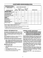
MAINTENANCE SCHEDULE
HOURLY OPERATING
FiLL IN DATES AS YOU COMPLETE
REGULAR SERVICE
MAINTENANCE TASK
PRESSURE WASHER
Chock/clean inletfilter and screen
Every25
Every100
Before
Hours or After First Hours or
Each Use Yearly
50 Hours
Yearly
SERVICE DATES
xt
Chock high pressurehose.
X
Check detergent hose.
X
X
Check gun and wand for leaks.
x$
Chock pump oil.
ENGINE
Chock oil level.
X
Change engine oil. _,
X_
Service air'cleaner.
X*_
Replace/clean spark plug.
Prepare for storage.
INTERVAL
X
Prepare unitfor storage if it isto remain idle
longerthan 30 days
1"Clean if clogged. Replace if perforated or tom
I: Change oil after first 50 operating hours, then after every 500 hours or yearly.
Change oil after first 5 hours, then after every 25 hours°
* Change sooner when operating under heavy load or high ambient temperature°
GENERAL
RECOMMENDATIONS
PRESSURE
Check Inlet Filter and Screen: Remove quick-connect and
examine inlet screen on the female connector and filter on pump
inlet fitting.Clean if either is dogged or replace if either is tom.
to
All adjustments in the Service and Adjustments section of
this manual should be made at least once each season.
Check High Pressure Hose: High pressure hose can
develop leaks from wear, kinking, abuse_ Inspect hose
each time before using it. Check for cuts, leaks, abrasions
or bulging of cover, or damage or movement of couplings.
If any of these conditions exist, replace hose immediately.
Once a year you should replace the spark plug and
clean or replace the air filter and check the gun and
wand assembly for wear° A new spark plug and clean
air filter assure proper fuel-air mixture and help your
engine run better and last longer.
BEFORE
Check Detergent Hose: Examine the filter' on the detergent hose and clean if clogged_ Hose should fit tightly on
barbed fitting. Examine hose for leaks or tears. Replace
the filter or hose if either is damaged.
EACH USE
,,
Check engine oil level.
•
Check water inlet filter and quick-connect
damage.
,,
Check high pressure hose for leaks.
•
Check detergent inlet hose and filter for damage.
,,
Check gun and wand assembly for leaks.
MAINTENANCE
DANGER: WATER SPRAYING FROM A LEAK iS t
CAPABLE OF INJEC_NG MATERIAL INTO SKIN.
NEVER REPAIR HIGH PRESSURE HOSE. RE-t
PLACE WITH HOSE THAT MEETS MINIMUM PRES- t
SURE RATING OF YOUR PRESSURE WASHER, J
The warranty of the high pressure washer does not cover
items that have been subjected to operator abuse or negligence. To receive full value from the warranty, operator
must maintain high pressure washer as instructed in this
manual.
Some adjustments will need to be made periodically
properly maintain your high pressure washer.
WASHER
screen for
Check Gun and Wand: Examine hose connection to gun
and make sure it is secure. Test trigger by pressing it and
making sure it springs back into place when you release it.
Put safety latch in ON position and test trigger. You should
not be able to press trigger.
Check Pump
information.
]4
Oil: Refer to PUMP MAINTENANCE
for
CUSTOMER
RESPONSIBILITY
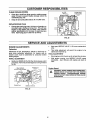
PUMP MAINTENANCE
Pump OI1: Change pump oil after first 50 hours of operation, then every 500 hours thereafter° To change pump oil,
follows these steps:
=
Place a proper container beneath the pump. You will
only need a small one because capacity is only 5
ounces,
=
Remove the Oil Drain Plug on bottom of pump and
drain oil into the container (Fig_ 22)°
FIG.
=
When engine crankcase is filled to proper level, install
and tighten oil fill plug.
SERVICE AIR CLEANER
Your engine will not run properly and may be damaged if
you run it using a dirty air cleaner°
OIL DRAIN PLUG
FIG. 22
•
When oil has drained completely,
plugo
o
Remove pump's oil fill plug, insert funnel and add
recommendedSAE
20W-40 oil until level reaches full
mark on gauge located on side of the pump_
o
Clean or replace the air cleaner paper filter once every 100
hours of operation or once a year, whichever comes first.
Clean or replace more often if operating under dusty or dirty
conditions. Replacements are available at your local Sears
Authorized Service Center_
reinstall oil drain
To clean or replace air cleaner (Fig. 24), follow these steps:
Reinstall the pump's oil fill plug.
ENGINE
---\
MAINTENANCE
CHECKING OIL LEVEL
See "PREPARATION BEFORE USE" for information on
checking oil level Oil level should be checked prior to each
use or at least every 5 hours of operation. Keep oil level
maintained.
CHANGING
AIR CLEANER
OIL
Change oil after first 5 hours of operation. Change oil
every 25 hours thereafter. If you are using your pressure washer under extremely dirty or dusty conditions,
or in extremely hot weather, change oil more often.
o
l
Change oil while engine is still warm from running, as
follows:
,_
FIG.
=
Loosen cover screws (these need not be removed) and
remove cover. Thoroughly clean inside of base and
cover.
=
Service cartridge by tapping gently on a flat surface,
Replace if dirty. Do not oil cartridge.
°
insert cartridge (new or used) and reassemble cover to
base as it was removed before. Tighten cover screws
securely.
CAUTION:
DISCONNECT
SPARK
PLUG FROM
WIRE
FROM
SPARK
PLUG AND KEEP
IT AWAY
SPARK PLUG.
I
Clean area around oildrain plug, remove plug and drain
oil completely into a suitable container (Fig. 23).
o
When all oil has drained, install and tighten oil plug.
o
Clean area around oil fill plug and remove oil fil! plug.
o
Fill engine crankcase with recommended oil until oil
level is at point of overflowing° About 20 ounces is
required° POUR SLOWLY.
15
CUSTOMER
CLEAN COOUNG
RESPONSiBILITiES
SYSTEM
•
Clean dirt or chaff from finger 0uard or rotating screen
even] 8 hours to prevent engine damage caused by
ovedleating (Fig. 25),
=
Keep dirt and combustible debris off of muffler area.
CLEAN OUT
CHAFFAND
DIRT
REPLACE SPARK PLUG
Change the spark plug every 100 hou rs of operation or'
once each year, whichever comes first, This will help
engine to start easier and run better. See pressure
washer specifications for the type of spark plug you
need. Spark plug gap is 0.030 inch (0.76mm).
FIG.
SERVICE AND ADJUSTMENTS
°
ENGINE ADJUSTMENTS
Carburetor:
=
This initial adjustment will permit the engine to be
started and warmed up.
FINAL ADJUSTMENT
Differences in fuel, temperature, altitude or load may require minor carburetor adjustment. Air cleaner and air
cleaner cover must be assembled to carburetor before
starting engine.
INITIAL ADJUSTMENT
•
Gently turn NEEDLE VALVE (Fig 26) clockwise until it
just closes_ Valve may be damaged by turning it inward
too far,
IDLE SPEED
ADJUSTING
SCREW
THROTTLE
STOP
o
Start engine and let itwarm up for at least five minutes.
°
With engine running, turn NEEDLE VALVE inward
(clockwise - lean mixture) until engine just starts to
slow=
Engine
\
Speed:
WARNING:
NEVER
TAMPER WITH
ENGINE
GOVERNOR WHICH
IS FACTORY
SET FOR
PROPER
ENGINE
SPEED.
OVERSPEEDING
ENGINE
ABOVE FACTORY HIGH SPEED SETTING CAN BE
DANGEROUS.
\
THROTTLE
Next open NEEDLE VALVE 1.1/2 turns counterclockwise.
NEEDLE
VALVE
FIG. 26
]6
STORAGE
AFTER
It is important to prevent gum deposits from forming in
essential fuel system parts such as the carburetor, fuel
filter, fuel hose or tank during storage_ Also, experience
indicates that alcohol-blended fuels (called "gasohot" or
using ethanol or methanol) can attract moisture which leads
to separation and formation of acids during storage. Acidic
gas can damage the fuel system of an engine while in
storage°
EACH USE
Water should not remain in the unit for long periods of time.
Sediments of minerals can deposit on pump parts and
"freeze" pump action. Follow these procedures after every
use:
Flush detergent
hose by placing the injector filter into
a pail of clear water while running Pressure Washer
with no771e in low pressure mode.
Flush for five minuteso
Shut off the engine
hoses.
and
let it cool, then
remove
To avoid engine problems, the fuel system should be
emptied before storage of 30 days or Ionger_ Follow these
instructions:
all
Protect Fuel System: Engines stored over 30 days need
to be protected or drained of fuel to prevent gum deposits
from forming in fuel system or on essential carburetor parts.
CAUTION:
BE SUREBEFORE
THE THROTTLE
LEVER IS iN
"STOP" POSITION
YOU CONTINUE.
tF
YOU START THE ENGINE WITHOUT THE PROPER
WATER SUPPLY CONNECTED, YOU CAN DAMAGE THE PUMP.
•
o
•
Empty the pump of all pumped liquids by pulling recoil
handte about 6 times. This should remove most of the
liquid in the pump.
Coil the high pressure hose and inspect it for damage.
Cuts in the hose or fraying of it could result in leaks and
loss of pressured Should any damage be found, replace
the hose. DO NOT attempt to repair a damaged hose
and use it, Replace the hose with the genuine Craftsman part.
For en_i_e protection use a fuel stabilizer (such as
STA-BIL . Mix stabilizer with fuel in fuel tank and run
engine for short time to circulate stabilizer through
carburetor.
-
If you did use "gasohol", run engine until engine stops
from lack of fuel. Make sure you have water supply to
pump inlet connected and turned ONo
Change Oi1: While engine is still warm, drain oil from
crankcase. Refill with recommended grade_
Oil Cyllnder Bore: Remove spark plug and pour about 1/2
ounce (15ml) of engine oil into the cylinder. Cover spark
plug hole with rag. Crank slowly to distribute oil
Drain water from hose and properly hang it on the wire
support provided on the guide handle
I .,_
NOTE: To protect the unit from freezing temperatures, you
can draw windshield washer fluid into the pump by pouring
the washer fluid into a 3-foot section of garden hose corn
nected to the inlet adapter and pulling the recoil handle
twice_
o
°
o
CAUTION'
HOLE WHENAVOIDSPRAYFROMSPARKPLUG
CRANKING ENG,NE SLOWLY.
Install spark plug.. Do not connect spark plug wire.
OTHER
Store in a clean, dr,/area.
LONG TERM STORAGE
WARNING: NEVER STORE ENGINE WITH FUEL iN
TANK INDOORS OR IN ENCLOSED, POORLY VENTILATED AREAS WHERE FUMES MAY REACH AN
OPEN FLAME, SPARK OR PILOT LIGHT AS ON A
FURNACE, WATER HEATER, CLOTHES DRYER
OR OTHER GAS APPLIANCE,
If you do not plan to use the Pressure Washer for more than
30 days, you must prepare the engine for long term storage.
o
Do not store gasoline from one season to another.
°
Replace your gasoline can if your can starts to rusL
Rust and/or dirt in your gasoline will cause problems.
o
tf possible, store your unit indoors and cover it to give
protection from dust and dirt,
o
Cover your unit with a suitable protective cover that
does not retain moisture.
IMPORTANT:
NEVER COVER YOUR PRESSURE
WASHER WHILE ENGINE AND EXHAUST AREAS ARE
WARM,
NOTE: As always, prepare the pressure washer pump as
you would after each use°
/7
TROUBLESHOOTING
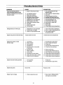
PROBLEM
Pump has following problems:
failure to produce pressure, erratic
pressure, chattering, loss of pressure,
low water volume.
CORRECTION
CAUSE
t.
Nozzle in low pressure mode.
2.
3
4o
5.
6.
7o
8.
Low regulator pressure
Water inlet is bIocked,
t. Pull nozzle backwardfor high
pressuremode°
2= Adjust regulator to desired setting.
3,, Clear'inlet
Inadequate water supply
Inlet hose is kinked or leaking
Clogged inlet hose strainer:
4o Provide adequate water flow.
5. Straighten inlet hose, patch leak,.
6. Check and clean inlethose strainer.
Detergent line is not submerged.
Water supply is over 140°F,
9. Outlet hose is blocked or leaks,
10. Gun leaks.
11. Nozzle is obstructed,
12, Pump is faulty°
7_ Submerge detergent line.
8o Provide cooler water supply,
9. Clear blocks in outlet hose,
10,, Replace gun,
1to Clear no.leo
12o Contact Sears Service Department.
Detergent fails to mix with spray_
1_ Detergent line is not submerged.
2
Chemical filter is clogged°
3o Nozzle is in high pressure mode_
1. Insertchemical line intodetergent.
2° Clean or replace fitter/detergent line.
3 Push nozzle forward for
low pressure mode°
Engine runsgood at no-load but "bogs
Enginespeed is too slow.
Contact Sears Service Department
Enginewill not start;or starts
and runsrough
1. Low oil level
2, Dirty air cleaner
3 Out of gasoline,
1.. Fill crankcase to proper level,
2, Clean or replace air cleaner,
3, Fill fuel tank,
4_ Stale gasoline_
5,, Spark plug wire not connected
to spark plug
6 Bad spark plug,
4,. Drain gas tank; fill with fresh fuel,
5, Connect wire to spark plug
7, Water in gasoline
8, Overchokh]go
7o Drain gas tank; fill with fresh fuel
8,. Open choke fully and crank engine,
Engine shutsdown during operation
Engine lacks power=
Engine "hunts" or falters.
6, Replace spark plug
9, Excessively rich fuel mixture
10, Intake valve stuck open or closed
11, Engine has lost compression,,
9. Contact Sears Service Department.
10r Contact Sears Service Department,
11_ Contact Sears Service Department
1_
2.
1,
Fill fuel tank,
2.
Fill crankcase to proper level.
Out of gasoline
Low oil level,,
Dirty air filter-,
Replace air filter
1_ Choke is opened too soon
]8
1, Move choke to halfway position
until engine runs smoothly.
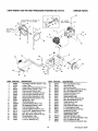
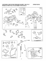
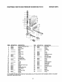
CRAFTSMAN
1800 PSI HIGH PRESSURE
WASHER
REPAIR
580.751510
PARTS
i,
Gu,BARREL
I
I°
40
6
3F z j
°G"
34
ITEM
PART NO.
1
2
3
4
5
6
7
8
9
10
11
12
13
14
15
16
17
18
19
20
21
95998
87628
89647
96016
95456
92479
22336
95567
92661
65852
22471
91842A
23365
88977
91841
32713
89314
39414
95902
75402
91094
DESCRIPTION
5 hp Briggs & Straiten Engine (1 req,)
Pump (1 req,)
Brass Water Hose Connector (t req,)
Quick-connect, Female (1 req,)
Quick-connect, Male (1 req.)
5/16" Conical Lock Washer (4 req,)
5/16"-24 x 3/4" Capscrew (4 req)
Gun And Wand Assembly (1 req)
Replacement Nozzle [blue] (1 req)
Spring Clip (1 req°)
#8-32 Nut (2 req)
Low Oil Shutdown Wire (1 req°)
#8 Shakaproof Washer (1 req,)
Low Oil Shutdown (1 req.)
Low Oil Shutdown Gasket (1 req.)
#10-32 x 5/8" Taptite Screw (2 req.)
3/16" Sq, x1.7/8" Key (1 req.)
M8-1,25 x 35ram Capscrew (4 req)
Mounting Base (I req,)
1/2" Dia, Push Nut (2 req )
2-1/4" x 8" Wheel (2 req,)
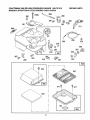
ITEM
PART NO,
22
23
24
25
26
27
28
29
30
31
32
33
34
35
36
37
38
22246
25391
93728
39253
52858
92235
91092
87841
57821
50190
91093
92067
95908
96633
86292
77584
89800
39
40
41
--
19
95587A
91630
49808
96596
D_ESCRIPTION
5/8" Lock Washer (2 req,)
Jam Nut (2 mq.)
Wheel Axle (2 mq,)
M8d 25 x 20mm Capscrew (6 req,)
M8-1.25 Flange Nut (12 mqo)
Rubber Grommet(1 req,)
Support Leg (2 req,)
Shock Mount(2 req,)
M8-125 x 40ramScrew (2 req,)
M8 x 25 Flat Washer (2 reqo)
Guide Handle (1 req3
Vinyl Cap (1 mq.)
Gun And Hose Holder (1 reqo)
#10 Flat Washer (2 reqo)
#10 Self-drilling Screw (3 req)
Handle Grip (1 req_)
Replacement Chemical
Injector Hose (1 req_)
Adjustable Nozzle (1 req,)
3/8" LD. x 25' Hose Assembly (1 req)
M12 Flat Washer (2 _'eq.)
Owner's Manual [notshown](1 req.)
Drawing No, 96597
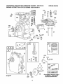
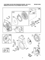
CRAFTSMAN
1800 PSi HIGH PRESSURE
BRIGGS & STRATTON 4-CYCLE ENGINE
WASHER
580.751510
133212-0159-01
REPAIR
PARTS
346
36 35
40
357
41
17
9
7
8
10
33
34
!
26
27
615
616
45
,f' 0
22
_"( _
\%.
--
220
219
20
592
X_
__,
_
J'-&_
1_o_9
LABEL
K_TI
_ REQUIRES SPECIAL TOOLS
wu
TO INSTALL. SEE REPAIR
INSTRUCTION MANUAL°
CRAFTSMAN
1800 PSI HIGH PRESSURE
BRIGGS & STRATTON 4-CYCLE ENGINE
WASHER
580.751510
133212-0159-01
REPAIR
PARTS
L90
634
'
97
202
_'
152
154
987
394
,4
392
203
432
435
205
127
433
187
127A
149
/
118
/
611 !
256
257
124
153
II_°/F/_
1012
217
_
"__
542
779
414
153
121 CARBURETOR KIT
_ 414A
_
_)3
_78
163
524
9
206A
7
216
201
232
!
621
191
467
358 GASKET
SET
2]
CRAFTSMAN 1800 PSi HIGH PRESSURE WASHER 580.751510
BRIGGS & STRATTON 4-CYCLE ENGINE 133212-0159-01
190
190A
208
REPAIR PARTS
280
271
209
181
268
269
_
270
985
224
204
520
223
267
526
265
916_
_;_62!
353
(_
354
969
967
971
535
l
966
22
_
CRAFTSMAN
1800 PSI HIGH PRESSURE WASHER
580.751510
BRIGGS & STRATTON 4-CYCLE ENGINE 133212-0159-01
REPAIR
PARTS
®
57
373
1016
85 ®
461
55
69A
515
69
456
59
58
w
23
305
73
%o_=o,
_81
613A
670
3_
O
304
334
346
455
_305
346A
i
i
335
356
23
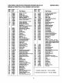
CRAFTSMAN 1800 PSi HIGH PRESSUREWASHER 580.751510
BRIGGS & STRATTON4-CYCLE ENGINE 133212-0159-01
Ref.
NO.
1
3
5
7
8
9
10
11
12
13
13A
14
15
16
17
18
19
20
21
22
23
24
25
26
27
28
29
30
32
33
34
35
36
37
40
41
45
45
52
55
56
57
56
59
60
65
69
69A
73
75
8I
9O
95
95
97
106
116
121
124
127
127A
149
152
153
154
Part
No.
495133
*299819
214040
*272157
294178
*27459
04621
66576
*270080
04221
94733
94679
04387
495645
494874
495641
495660
*495307
55768
94682
297229
222698
393819
399067
26026
268909
299430
221890
94745
262464
261044
268552
262750
222443
93312
491442
268642
212733
* _271936
494846
493824
262594
280406
396892
393152
04686
280973
224322
224533
224951
222263
495426
93499
225793
495046
491177
231533
495606
94616
220352
223789
26336
260575
490589
93527
Part Name
Cyilnder Assembly
Oil Seal
Cylinder Head
Cylinder Head Gask,_t
Breather - Valve Chamber
Valve Cover Gasket
Screw. Breather Mounting Sam
Breather Tube Grommet
Cylinder Head Screw _ 2-3/32"
Cylinder Heed Stud
Cylinder Heed Screw
Olt Drain Plug (magnetic)
Crankshaft
NOTE: To replace crankshaft pin,
order Part No. 230978
Ball Bearing (PTO side)
Crankcase Cover Assembly
Bushing -- Oil Seal
OII Seal
OII Filler Plug
Hex Head Screw
Flywheel
Flywheel Key
Piston Assembly
Ring Set
Piston Pin Lock
Piston Pin Assembly
Connecting Rod Assembly
Connecting Rod Dipper
Connecting Rod Screw
Exhaust Valve
Intake Valve
Intake Valve Spring
Exhaust Valve Spring
Flywheel Guard
Valve Spring Retainer
Retainer Valve
Valve Tappet
Cam Gear
Carburetor Mounting Gasket
Rewind Starting Housing
Rewind Starter Pulley
Rewind Starter Spring
Rewind Starter Rope (cut to length)
Starter Handle Insert
Rewind Starter Handle
Housing Mounting Screw
Washer
Washer
Rotating Screen
Flywheel Washer
Screw Lock
Carburetor Assembly
Throttle,Valve_to-Shaft
Screw
Carburetor Throttle
Throttle Shaft and Lever
Choke Valve Group
Needle Valve
Carburetor Kit
Hsx Head Screw
Welch Plug
Welch Plug (Mixing Chamber)
Needle Valve Spring
Throttle Adjustment Spring
Screw and Collar
Round Head Screw 5-A0 x 5/8"
Ref.
No.
Part
NO.
163
180
181
187
190
190A
191
201
202
2O3
204
2O5
295
207
208
209
216
2t7
2t9
220
222
223
224
227
230
232
256
295
267
268
.271935
495405
494559
231068
94712
94677
269
270
271
280
300A
304
395
306
308
332
333
334
335
337
346
346A
353
354
356
358
353
373
392
394
26099
63426
290568
223798
393615
495795
94619
224820
224738
92254
397358
93613
93414
492167
94680
93705
92791
90576
398808
495603
19069
92987
262328
$272538
¥272489
25228O
25227O
28O720
222962
23152O
94081
25655
262323
262262
262359
262281
391737
221551
490649
223455
93491
490374
222450
262310
223813
221535
93496
66986
REPAIR PARTS
Part Name
Air Cleaner Mounting Gasket
Fuel Tank Assembly
Fuel Tank Cap
Fuel Pipe
Screw - Sam
Screw - Sam
Fuel Tank Mounting Gasket
Governor Link
Throttle Link
Bell Crank
Control Lever Bushing
Shoulder Screw
Stop Nut
Control Rod Spring
Speed Control Rod
Governor Spring
Choke LIInk
Choke Spdng
Governor Gear
Thrust Washer
Control Bracket
Governor Control Lever
Governor Control Lever Rivet
Governor Lever Assembly
Governor Lever Washer
Return Spring
Bell Crank
Casing Clamp
Screw
Control WILe Casing _ 48" long
If longer casing Is needed, specify
lenght In Inches; If shorter casing IJ
needed, order No, 66986 and cut to
required length.
Control Wire
Casing Locknut
Control Lever
Control Rod Bracket
Exhaust Muffler.
Blower Housing
Blower Housing Mounting Screw
Cylinder Shield
Cylinder Head Cover
Flywheel Nut
Armature Assembly
Sam Screw
Armature Mounting Screw
Spark Plug -- 1-718" high, 48ram
Screw
Screw
Lock W_eher
Hex Nut
Ground Wire
Gasket Set
Flywheel Puller
Hex Nut
Diaphragm
Diaphragm
Spdng
* Included in Gasket Set -- Part No, 495603
Included in Carburetor Kit -- Part Noo 495606
24
CRAFTSMAN
BRIGGS
& STRATTON
Ref,
Part
NO.
NO.
220082
221198
221377
93265
214021
93141
494770
224321
492883
262626
280715
262625
93722
94659
223786
231550
432
433
434
435
455
456
459
461
467
515
520
626
527
528
529
535
535
542
552
562
592
608
613A
614
615
67838
491435
494279
93572
231079
92613
231 082
299406
93_5
93306
i
1800 PSI HIGH PRESSURE
933o7
4-CYCLE
ENGINE
WASHER
580.751510
REPAIR
PARTS
133212-0159-01
Ref.
Part
Part Name
NO,
NO.
Part Name
Washer
Washer
Spring Cap
Dlaphragm Cover Pin
Dlaphragm Cover
Blaphregm Cover Screw
Flywheel Cup
Retainer Sprlng
Ratchel Pawl
Spring Pin
Control Knob
Spring
Terminal
Sam Screw
Breather Tube Clamp
Breather Tube
NOTE: 2315,50_
Breather Tube
Breather Tube Grommet
Air Filter
Air Cleaner Aasebmly
Screw
Governor Crank Bushing
Governor Lever Bolt
Noo 10-24 Hax Nut
Rewind Starter Assembly
Hex Head Shoulder Screw
Hair Pin Cotter
E-Ring Retatner
616
621
634
635
655
670
676A
679
650
741
851
869
870
671
653
916
966
967
968
969
971
978
985
087
1012
1016
1019
231077
396847
271853
66538
222508
251065
3957O0
270832
221839
231696
221708
211787
211436
262001
272309
280321
492797
491508
495357
490073
94018
271736
398525
398970
490507
490817
491100
Governor Crank (1/4 = alia.)
Stop Switch
Throttle Shaft Washer (foam)
Spark Plug Elbow
Anchor Spring
Armature Spacer
Exhaust Deflector
Washer (foam)
Washer (brass)
Timing Gear (plain bearing)
Ignition Cable Terminal
intake Valve Seat
Exhaust Valve Seat
Exhaust Valve Guide
*Muffler Gasket
Governor Gear Rack
Air Cleaner Base
Air Filter
Atr Cleaner Cover
Cover Mounting Screw
Alr Cleaner Screw
*Cover Gasket
Insulator
Throttle Shaft Seal
Retainer Link
Spacer
Decal (label) Kit
FULL ONE YEAR WARRANTY ON CRAFTSMAN HIGH PRESSURE WASHER
For one year from the date of purchase, when this Craftsman High Pressure Washer is maintained and
operated according to the instructions in the owner's manual, Sears will repair, free of charge, any defect in
material and workmanship°
If this washer is used for commercial purposes, this warranty applies for only 90 days from the date of
purchase, If this high pressure washer is used for rental purposes, this warranty applies for only 30 days
after date of purchase,
FULL TWO YEAR WARRANTY
ON GASOLINE
ENGINE
For two years from the date of purchase, when this gasoline engine is maintained and operated according
to the instructions in the owner's manual, Sears will repair, free of charge, any defect in material and
workmanship,
If the Gasoline Engine is used for commercial or rental purposes, this warranty applies for only one year from
the date of purchase.
This warranty does not cover:
,,
Expendable items such as spark plugs and air filters, which become worn during normal use.
,,
Repairs necessary because of operator abuse or negligence, including damage resulting from no water
being supplied to pump or failure to maintain the equipment according to the instructions contained in
the owner's manual°
WARRANTY SERVICE IS AVAILABLE BY RETURNING THE HIGH PRESSURE WASHER TO THE
NEAREST SEARS SERVICE CENTER/DEPARTMENT THROUGHOUT THE UNITED STATES.
This warranty gives you specific legal rights and you may also have other rights, which vary from state to
state.
SEARS, ROEBUCK AND CO.0 D/817 WA, Hoffman Estates, IL 60179
25
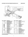
CRAFTSMAN
1800 PSI HIGH PRESSURE
WASHER
25
3_
23
580.751510
REPAIR
PARTS
24 57 22
t,."l,:'j 2_
4_
5--
7_
8_
5_
9_
11-12--
18--
i
64
63
54
55
ITEM
KIT PART NO.
DESCRIPTION
ITEM
KIT PART NO.
DESCRIPTION
1
2
3
4
5
6
7
8
9
!0
11
12
16
17
18
19
20
21
22
23
24
25
26
27
28
96737
96738
96739
Pressure Reglulator Knob
Ring Nut
Spring Guide
Spring
Plate
Upper Piston
O-ring
Piston Guide
O-ring
O-ring
Lower Piston
Combiset Body
Set Screw (2 reqo)
Ptn
O-ring
O-ring
Knob
Detergent Check Valve
O-ring
Stainless Steel Ball
Valve Spring
O-ring
Detergent Fitting
O-ring
Washer
29
32
33
34
40
41
45
46
47
48
49
50
51
54
55
57
61
62
63
64
65
66
67
68
89361
89361
3/8" Fitting
O-ring
Washer
1/2" Fitting
Pin
O-ring
O-ring
Suction Connector
inlet Filter
Hose Connector
Hose Connector
O-ring
O-ring
O-r_ng
Outlet Connector
Gauge Valve
Valve Seat
Connector
Detergent injector
O-ring
O-ring
Spring
Trap Valve
O-ring
....
--_
89361
89361
96740
96741
89361
89361
89361
89361
89361
89361
89361
89646
89361
89361
89361
89361
89361
89361
89361
89361
89361
IF YOU NEED TO REPLACE A PART NOT INCLUDED IN A KIT OR HAS NO PART NUMBER LISTED, YOU MUST
REPLACE THE ENTIRE PUMP_
26
CRAFTSM
AN 1800 PSI HIGH PRESS UR E WASHER
580.751510
REPAIR
PARTS
,KIT 89360
KIT 89358
I
22
23
24
P5 26 27
28
29
30
-_'-"'_IL('ll! .:ll
//fP'_
_3
_
ITEM
1
2
7
8
9
10
ll
12
13
14
15
16
17
18
19
20
21
22
23
24
25
26
27
28
29
KIT PART NO.
96742
89360
89360
89360
89360
89360
89358
B935B
96743
945O5
DESCRIPTION
M6 x 60ram Head Bolt (6 req,)
1/8" Plug [optional] (1 req.)
Inlet/outlet Valve Cap (6 req)
Valve Cap O-dng (6 reqo)
Inlet/outlet Valve (6 reqo)
Inlet/outlet Valve O-ring (6 req.)
Water Seal (3 req.)
Water Seal (3 reqo)
Piston Guide (3 req)
O, ring (3 req.)
Water Seal (3 reqo)
Oil Seal (3 req.)
Crankshaft BearingEnd Cap (1 req.)
O-ring (1 raq.)
Snap Ring (1 req)
Crankshaft Beadng (1 req,)
Crankshaft spacer (1 req)
Pump Body (1 req.)
Oil Dipstick (1 reqo)
M8 Nut (3 req.)
M8 Washer (3 req.)
Piston(3 req.)
O-dng (3 reqo)
Spacer (3 req.)
Connecting Rod (3 req.)
ITEM
30
3t
32
33
34
35
36
37
38
39
40
41
42
IF YOU NEED TO REPLACE A PART NOT INCLUDED IN A
REPLACE THE ENTIRE PUMP.
62
67
8
69
70
71
79
80
81
82
84
62 _-
, ...............
-
DESCRIPTION
Pin (3 req,)
M5 x 20mm Cover Screw (6 req.)
Cover (1 req.)
...........................
O-ring (I req.)
Sea! (I req.)
Seal (1 req.)
Connecting Rod Cap (3 req.)
Cover Gasket (3 req.)
89358
O-dng (3 req,)
Drain Plug (2 reqo)
Pump Head (1 req.)
O-ring (1 req,)
Cap (1 req_)
K1TPART NO.
....
89358
....
....
....
........
Seal (1 reqo)
Crankshaft (I req.)
Bearing (1 req.)
..... Pump Mounting Flange(1 reqo)
M6 x 16mm Flanged Bolts (1 req)
5/16"-24 x 3/4" BoIls (4 req.)
Spacer (1 req°)
M6 x 25mm Screw (1 req.)
M6 x !2ram Screw (4 req,)
Cover (1 req.)
.............RertainingRing (1 req,)
KIT OR HAS NO PART NUMBER LISTED, YOU MUST
27
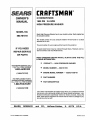
CRRFTSMRN°
OWNER'S
MANUAL
5 HORSEPOWER
1800 PSI
2,5 GPM
HIGH PRESSURE
WASHER
MODEL NO.
580.751510
Each High Pressure Washer has its own model number. Each engine has
its own part number.
The model number for your pressure washer will be found on a decal
attached to the uniL
The part number for your engine will be found in the parts list.
IF YOU NEED
REPAIR SERVICE
All parts listed herein may be ordered through Sears, Roebuck and Co.
Service Centers and most Retail Stores.
OR PARTS
WHEN ORDERING
REPAIR
LOWING INFORMATION:
FOR REPAIR SERVICE CALL
THIS TOLL FREE NUMBER
1-800-4,4:IEPAIR
(1-800-473-7247)
FOR REPLACEMENT PARTS
INFORMATION AND ORDERING,
CALL THIS TOLL FREE NUMBER:
@
PRODUCT--
®
MODEL
®
ENGINE
®
PART NUMBER
•
PART DESCRIPTION
PARTS,
ALWAYS
HIGH PRESSURE
NUMBER--
MODEL
GIVE
THE FOL-
WASHER
580.751510
NUMBER-=
133212-0159-01
1-800-FON-PART
(1-8O0-366-7278)
Your Sears merchandise has added value when you consider that Sears
has service units nationwide staffed with Sears trained technicians__professional technicians specifically trained on Sears products, having the
parts, tools and the equipment to ensure that we meet our pledge to you,
we service what we sell.
SEARS,
ROEBUCK
Part No,, 96596 Revision 3 (6/20/95)
and
CO.,
Hoffman
Estates,
IL
60179
U.S.A.
Priated in U,S A