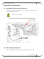
1
ConnectX®-2 VPI Dual Port Adapter Card User
Manual
P/N:
MHGH29B-XTR, MHGH29B-XSR
Rev 1.1.5
www.mellanox.com
Rev 1.1.5
NOTE:
THIS HARDWARE, SOFTWARE OR TEST SUITE PRODUCT (“PRODUCT(S)”) AND ITS RELATED DOCUMENTATION ARE
PROVIDED BY MELLANOX TECHNOLOGIES “AS-IS” WITH ALL FAULTS OF ANY KIND AND SOLELY FOR THE PURPOSE
OF AIDING THE CUSTOMER IN TESTING APPLICATIONS THAT USE THE PRODUCTS IN DESIGNATED SOLUTIONS. THE
CUSTOMER'S MANUFACTURING TEST ENVIRONMENT HAS NOT MET THE STANDARDS SET BY MELLANOX
TECHNOLOGIES TO FULLY QUALIFY THE PRODUCTO(S) AND/OR THE SYSTEM USING IT. THEREFORE, MELLANOX
TECHNOLOGIES CANNOT AND DOES NOT GUARANTEE OR WARRANT THAT THE PRODUCTS WILL OPERATE WITH THE
HIGHEST QUALITY. ANY EXPRESS OR IMPLIED WARRANTIES, INCLUDING, BUT NOT LIMITED TO, THE IMPLIED
WARRANTIES OF MERCHANTABILITY, FITNESS FOR A PARTICULAR PURPOSE AND NONINFRINGEMENT ARE
DISCLAIMED. IN NO EVENT SHALL MELLANOX BE LIABLE TO CUSTOMER OR ANY THIRD PARTIES FOR ANY DIRECT,
INDIRECT, SPECIAL, EXEMPLARY, OR CONSEQUENTIAL DAMAGES OF ANY KIND (INCLUDING, BUT NOT LIMITED TO,
PAYMENT FOR PROCUREMENT OF SUBSTITUTE GOODS OR SERVICES; LOSS OF USE, DATA, OR PROFITS; OR BUSINESS
INTERRUPTION) HOWEVER CAUSED AND ON ANY THEORY OF LIABILITY, WHETHER IN CONTRACT, STRICT LIABILITY,
OR TORT (INCLUDING NEGLIGENCE OR OTHERWISE) ARISING IN ANY WAY FROM THE USE OF THE PRODUCT(S) AND
RELATED DOCUMENTATION EVEN IF ADVISED OF THE POSSIBILITY OF SUCH DAMAGE.
Mellanox Technologies
350 Oakmead Parkway Suite 100
Sunnyvale, CA 94085
U.S.A.
www.mellanox.com
Tel: (408) 970-3400
Fax: (408) 970-3403
Mellanox Technologies, Ltd.
PO Box 586 Hermon Building
Yokneam 20692
Israel
Tel: +972-4-909-7200
Fax: +972-4-959-3245
© Copyright 2010. Mellanox Technologies. All rights reserved.
Mellanox, BridgeX, ConnectX, Virtual Protocol Interconnect, InfiniBlast, InfiniBridge, InfiniHost, InfiniRISC, InfiniScale, and InfiniPCI
are registered trademarks of Mellanox Technologies, Ltd. CORE-Direct, FabricIT, and PhyX are trademarks of Mellanox Technologies, Ltd.
All other trademarks are property of their respective owners.
All other marks and names mentioned herein may be trademarks of their respective companies.
ConnectX-2 VPI Card User Manual
2
Mellanox Technologies
Document Number: 3164
ConnectX-2 VPI Card User Manual
Rev 1.1.5
Table of Contents
Table of Contents
3
List of Figures
4
List of Tables
5
Revision History
6
About this Manual
7
Intended Audience 7
Related Documentation 7
Online Resources 7
Document Conventions 7
Chapter 1 Overview
1.1
1.2
1.3
1.4
8
Adapter Cards Covered in this Manual
Mellanox Part Numbering Legend
Finding the GUID/MAC and Serial Number on the Adapter Cards
Safety Warnings
9
10
11
11
Chapter 2 Adapter Card Interfaces
2.1
2.2
2.3
2.4
13
I/O Interfaces
Power
Memory
VPD Layout
13
17
17
17
Chapter 3 Driver Software and Firmware
19
3.1 Driver Software
3.2 Updating Adapter Card Firmware
3.3 FlexBoot
19
19
19
VPI Adapter Card Installation
21
4.1 Hardware and Software Requirements
4.2 Installation Instructions
4.3 Cables and Modules
21
21
21
Chapter 4
Appendix A Specifications
23
A.1 Board Mechanical Drawing and Dimensions 23
A.2 EMC Certification Statements 23
A.3 MHGH29B-X[ST]R Specifications 26
Appendix B Interface Connectors Pinout
27
B.1 I2C-Compatible Connector Pinout 27
B.2 CX4 Connector Pinout 28
B.3 PCI Express x8 Connector Pinout 28
Appendix C Replacing a Tall Bracket With a Short Bracket
29
C.1 Removing Tall Bracket 29
C.2 Replacing a Bracket 31
Appendix D Avertissements de sécurité d’installation (Warnings in French)
34
Appendix E Sicherheitshinweise (Warnings in German)
35
Appendix F Advertencias de seguridad para la instalación (Warnings in Spanish)
36
Mellanox Technologies
3
Rev 1.1.5
List of Figures
Figure 1:
CX4 InfiniBand VPI Adapter Card
9
Figure 2:
Card Product Label
11
Figure 3:
Port Numbering
13
Figure 4:
LED - Port Association
16
Figure 5:
Physical and Logical Link Indications
16
Figure 6:
I2C Connector
16
Figure 7:
Flash Jumper
17
Figure 8:
Schematic of the ConnectX-2 VPI Adapter Card with CX4 Connectors
23
Figure 9:
Compatible Connector Plug and Pinout
27
Figure 10: CX4 Connector Pinout
28
Figure 11: Tall Bracket of a Dual IB Port Card
29
Figure 12: Connector Retention Clip
29
Figure 13: Extracting Connector Clip
30
Figure 14: Bracket Screws
30
Figure 15: Rotate the Bracket to Detach it From the Card
31
Figure 16: Place Short Bracket onto Card
31
Figure 17: Attach Bracket onto Card using Screws
32
Figure 18: Sliding Connector Clip Evenly
32
Figure 19: Assembled Short Bracket
33
4
Mellanox Technologies
ConnectX-2 VPI Card User Manual
Rev 1.1.5
List of Tables
Table 1:
Revision History Table
6
Table 2:
Documents List
7
Table 3:
Adapter Cards
9
Table 4:
Mellanox Cards Part Numbering Key
10
Table 5:
Supported Port configurations
15
Table 6:
Unsupported Port Configurations
15
Table 7:
LEDs
16
Table 8:
Jumper Configuration
17
Table 9:
VPD Layout for MHGH29B-X[ST]R
18
Table 10:
Hardware and Software Requirements
21
Table 11:
Adapter Cards Certification Status
24
Table 12:
Specifications for MHGH29B-X[ST]R
26
Table 13:
I2C-Compatible Connector Pinout
27
Table 14:
InfiniBand 4X Connector Pinout
28
Mellanox Technologies
5
Rev 1.1.5
Revision History
This document was printed on 7/1/10.
Table 1 - Revision History Table
6
Date
Rev
July 1st,
2010
1.1.5
Added link to card table,
June 28th,
2010
1.1.4
Removed single card graphic,
June 22nd,
2010
1.1.3
Removed Gen 1 cards
June 03th,
2010
1.1.2
Added Safety Warnings in Spanish
May 13th,
2009
1.1.1
Minor formatting
April 2009
1.1
New power numbers
Oct. 2009
1.0
Initial Release
Mellanox Technologies
Comments/Changes
ConnectX-2 VPI Card User Manual
Rev 1.1.5
About this Manual
This User Manual describes Mellanox Technologies ConnectX®-2 Dual Port VPI InfiniBand and
Ethernet PCI Express x8 adapter cards. It provides details as to the interfaces of the board, specifications, required software and firmware for operating the board, and relevant documentation.
Intended Audience
This manual is intended for the installer and user of these cards.
The manual assumes basic familiarity with InfiniBand® and Ethernet networks and architecture
specifications.
Related Documentation
Table 2 - Documents List
Mellanox Firmware Tools (MFT) User Manual
Document no. 2204UG
User Manual describing the set of MFT firmware management tools for a
single node.
See http://www.mellanox.com => Downloads => Firmware Tools
IBTA Specification Release 1.2.1
InfiniBand Architecture Specification
IEEE Std 802.3 Specification
This is the IEEE Ethernet specification
http://standards.ieee.org/getieee802
PCI Express 2.0 Specifications
Industry Standard PCI Express 2.0 Card Electromechanical Specification,
Rev 1.3.
Online Resources
• Mellanox Technologies Web pages: http://www.mellanox.com
• Mellanox Technologies Firmware download Web page:
http://www.mellanox.com => Downloads => Firmware
Document Conventions
When discussing memory sizes, MB and MBytes are used in this document to mean size in mega
bytes. The use of Mb or Mbits (small b) indicates size in mega bits.
Mellanox Technologies
7
Rev 1.1.5
1
Overview
Overview
This document is a User Manual for Mellanox Technologies VPI adapter cards based on the
MT25408, ConnectX®-2 VPI integrated circuit device. The cards described in this manual have
the following main features:
• IEEE Std 802.3 compliant
• PCI Express 2.0 (1.1 compatible) through an x8 edge connector up to 5GT/s
• CPU offload of transport operations
• CORE-Direct application offload
• End-to-end QoS and congestion control
• Hardware-based I/O virtualization
• TCP/UDP/IP stateless offload
• Fibre Channel encapsulation (FCoIB or FCoE)
• RoHS-R6
• Two bracket heights: short and tall
• CX4 ports for connecting InfiniBand and Ethernet traffic (4X connectors)
8
Mellanox Technologies
ConnectX-2 VPI Card User Manual
1.1
Rev 1.1.5
Adapter Cards Covered in this Manual
Table 3 lists the VPI adapter cards described in this manual.
Table 3 - Adapter Cards
Ordering Part Number
(OPN)
PCI Express
SERDES
Speed
IB SDR /
DDR/
QDR
ETH
Speed
Short /
Tall
Bracket
IC
Part Number
MHGH29B-XTR
5.0 GT/s
DDR
1/10 Gb/s
Tall
MT25408B0-FCCR-GI
MHGH29B-XSR
5.0 GT/s
DDR
1/10 Gb/s
Short
MT25408B0-FCCR-GI
Figure 1: CX4 InfiniBand VPI Adapter Card1
1. The cards have a similar form and fit. The main visible difference is in the bracket height. All of these cards are RoHS-R6 compliant (lead free)
Mellanox Technologies
9
Rev 1.1.5
1.2
Overview
Mellanox Part Numbering Legend
Table 4 describes the Mellanox Technologies adapter cards part numbering legend.
Table 4 - Mellanox Cards Part Numbering Key
Adapter Card
OPN
MHTS#I-XBR
Field
Decoder
M
Mellanox
Technologies
H
Adapter Type
H = InfiniBand Host Channel Adapter, N = Ethernet Network Interface Card
T
Media
E = CX4 SDR, G = CX4 DDR, P = SFP+, T = UTP, Z = one SFP+ connector and
one QSFP connector
S
Adapter
Architecture
T= InfiniHost®, A = InfiniHost® III Ex, S = InfiniHost® III Lx,
H = ConnectX®
#
# ports
1 = 1, 2 = 2
I
Host Interface
X = PCI-X, 4 = PCIe x4, 8 = PCIe x8, 9 = PCIe (SerDes @ 5.0 GT/s)
G
Generation
<blank> = Initial product generation
-
Separator
X
Memory Size
X = MemFree, 1=128MB, 2=256MB, 3=512MB
B
Bracket
S = Short, T = Tall, N = None
R
RoHS
<blank> = non RoHS, C = RoHS R-5 w/ Exemption, R = RoHS R-6 Lead-Free
For example, the part number MHGH28B-XSR describes Mellanox Technologies’ ConnectX®-2
VPI card with dual CX4 ports, a PCIe2.0 x8 2.5GT/s interface, no on-board memory (mem-free), a
short PCI bracket, and RoHS R6 compliance. Using the legend,
• field M = M to indicate a Mellanox Technologies product,
• field H = H to indicate an InfiniBand Adapter Card,
• field T = G to indicate CX4 DDR,
• field S = H to indicate the ConnectX family,
• field # = 2 to indicate two ports,
• field I = 8 to indicate PCI Express 2.0 x8 running at 2.5GT/s,
• field G = B to indicate Generation B ConnectX-2
• field X = X to indicate no on-board memory,
• field B = S to indicate a short bracket, and
• field R = R to indicate RoHS R6 (lead free) compliance
10
Mellanox Technologies
ConnectX-2 VPI Card User Manual
1.3
Rev 1.1.5
Finding the GUID/MAC and Serial Number on the Adapter Cards
All Mellanox adapter cards have a label on the printed side of the adapter card that has the card
serial number, the card MAC for Ethernet protocol, and the card GUID for InfiniBand protocol.
VPI Cards have both a MAC and a GUID. For VPI cards the MAC is derived from the GUID.
Figure 2: Card Product Label
S /N :M T 0744 X 00012
REV: X1
P /N :M H G H 29B -X T R
G U ID : 0002 C 902002642 F C
M A C : 0002 C 901122 B
M ade in IL
1.4
Safety Warnings
For safety warnings in French see “Avertissements de sécurité d’installation (Warnings in French)”
on page 34. For safety warnings in German see “Sicherheitshinweise (Warnings in German)” on
page 35. For safety warnings in Spanish see “Advertencias de seguridad para la instalación (Warnings in Spanish)” on page 36.
1. Installation Instructions
Read all installation instructions before connecting the equipment to the power
source.
2. Over-temperature
This equipment should not be operated in an area with an ambient temperature
exceeding the maximum recommended: 55°C (131°F).
To guarantee proper air flow, allow at least 8cm (3 inches) of clearance around
the ventilation openings.
3. During Lightning - Electrical Hazard
During periods of lightning activity, do not work on the equipment or connect
or disconnect cables.
4. Copper Cable Connecting/Disconnecting
Some copper cables are heavy and not flexible, as such they should be carefully attached to or detached from the connectors. Refer to the cable manufacturer for special warnings and instructions.
Mellanox Technologies
11
Rev 1.1.5
Overview
5. Equipment Installation
This equipment should be installed, replaced, or serviced only by trained and
qualified personnel.
6. Equipment Disposal
Disposal of this equipment should be in accordance to all national laws and
regulations.
7. Local and National Electrical Codes
This equipment should be installed in compliance with local and national electrical codes.
12
Mellanox Technologies
ConnectX-2 VPI Card User Manual
Rev 1.1.5
2
Adapter Card Interfaces
2.1
I/O Interfaces
Each adapter card includes the following interfaces:
• 4X InfiniBand/Ethernet Copper ports
• PCI Express x8 edge connector
• I/O panel LEDs
• I2C compatible connector (for debug)
For dual port cards, port 1 connects to connector 1 of the device, while port 2 connects to connector 2 of the device.
Figure 3: Port Numbering
Port 1
Port 2
Dual Port
2.1.1 InfiniBand Interface
The ConnectX®-2 device (MT25408B0) is compliant with the InfiniBand Architecture Specification,
Release 1.2.1. It has compliant 4X ports, with four Tx/Rx pairs of SerDes. VPI adapter cards (listed
in Table 3 on page 9) based on this device provide access to its ports by means of CX4 connectors.
Mellanox Technologies
13
Rev 1.1.5
Adapter Card Interfaces
These ports utilize a ‘media detect circuit’ that applies power to active copper cables and fiber
solutions connected to the port connectors.
2.1.2 Ethernet Interface
The ConnectX®-2 device (MT25408B0) is compliant with the IEEE Std 802.3. VPI adapter cards
(listed in Table 3 on page 9 ) based on this device provide access to the Ethernet ports by means of
CX4 connectors.
2.1.3 VPI Port Configuration
VPI ports are auto-sensing but can be manually configured using a script.
Port type management:
By default both ConnectX® -2 ports are initialized as Infiniband ports. If you wish to change the
port type use the connectx_port_config script after the driver is loaded.
The script is installed as part of the Mellanox OFED for Linux package (under /sbin). See the Mellanox OFED for Linux User’s Manual available at http://www.mellanox.com/content/
pages.php?pg=products_dyn&product_family=26&menu_section=34.
Running "/sbin/connectx_port_config -s" will show the current port configuration for all ConnectX® -2 devices.
Port configuration is saved in the file: /etc/infiniband/connectx.conf. This saved configuration is
restored at driver restart only if done via "/etc/init.d/openibd restart".
Possible port types are:
• "eth" - Always Ethernet
• "ib" - Always Infiniband
• "auto" - Link sensing mode - detect port type based on the attached network type. If no link is
detected, the driver retries link sensing every few seconds.
Each port link type can be configured for each device in the system at run time using the "/sbin/
connectx_port_config" script. This utility will prompt for the PCI device to be modified (if there is
only one it will be selected automatically). At the next stage the user will be prompted for the
desired mode for each port.
The desired port configuration will then be set for the selected device. Note: This utility also has a
non interactive mode:
"/sbin/connectx_port_config [[-d|--device <PCI device ID>] -c|--conf <port1,port2>]".
14
Mellanox Technologies
ConnectX-2 VPI Card User Manual
Rev 1.1.5
The following configurations are supported by VPI:
Table 5 - Supported Port configurations
Port 1
Port 2
Ethernet
Ethernet
IB
IB
auto-sensing
auto-sensing
IB
Ethernet
IB
auto-sensing
auto-sensing
Ethernet
The following options are not supported:
Table 6 - Unsupported Port Configurations
Port 1
Port 2
Ethernet
IB
Ethernet
auto-sensing
auto-sensing
IB
2.1.4 PCI Express Interface
The ConnectX®-2 adapter cards support PCI Express 2.0 (1.1 compatible) through an x8 edge connector. The device can be either a master initiating the PCI Express bus operations or a slave
responding to PCI bus operations.
2.1.5 LED Assignment
The board has I/O LEDs located on the I/O panel- 2 LEDs per port. The green LED, when lit, indicates that the driver is running and a valid physical connection between nodes exists. If the green
LED is blinking, it indicates a problem with the physical link. The yellow LED when lit, indicates
a valid data activity link, this is the logical link. The yellow LED lights up when the network is
discovered over the physical link. A valid data activity link without data transfer is designated by a
constant yellow LED indication. A valid data activity link with data transfer is designated by a
blinking yellow LED indication. If the LEDs are not active, either the physical link or the logical
link (or both) connections have not been established.
Mellanox Technologies
15
Rev 1.1.5
Adapter Card Interfaces
Figure 4: LED - Port Association
Port 1
Port 2
Figure 5: Physical and Logical Link Indications
Table 7 - LEDs
Port Number
LED Name
Port 1
Physical Link - Green
Constant on indicates a good physical link
Blinking indicates a problem with the Physical
link
Data Activity - Yellow
Blinking indicates Data Transfer
Constant on indicates no Data Transfer
Port 2
Port 1
Port 2
Physical Link - Green
Constant on indicates a good physical link
Blinking indicates a problem with the Physical
link
Data Activity - Yellow
Blinking indicates Data Transfer
Constant on indicates no Data Transfer
The short bracket has the same port and LED footprint as the tall bracket.
2.1.6 I2C Compatible Interface
A three-pin header on the adapter card is provided as the I2C compatible interface. See Figure 8 on
page 23 for the location on the board.
Figure 6: I2C Connector
16
Mellanox Technologies
ConnectX-2 VPI Card User Manual
2.2
Rev 1.1.5
Power
All adapter cards receive 12V and 3.3V power from the PCI Express Edge connector. All other
required power voltages are generated by on-board switch mode regulators. See “Specifications”
on page 23.
2.3
Memory
The adapter cards support multiple memory devices through the PCI Flash, and I2C compatible
interfaces.
2.3.1 System Memory
The adapter card utilizes the PCI Express interface to store and access IB fabric and/or Ethernet
fabric connection information and packet data on the system memory.
2.3.2 Flash
Each of the adapter cards include one 16MB SPI Flash device (M25P16-VME6G device by ST
Microelectronics) accessible via the Flash interface of the MT25408B0 ConnectX®-2 VPI device.
There is a jumper on each adapter card that indicates to the device whether an on-board Flash
device is to be used. Table 8 provides information on this jumper. See the schematic in Figure 8 on
page 23 for the jumper location.
Table 8 - Jumper Configuration
Description
Flash present/
not present
Option
connection open – Flash present
connection shorted – Flash not present
Card Default
Configuration
connection open –
Flash present
Comments
Header 1x2
Figure 7: Flash Jumper
2.3.3 EEPROM
Each board incorporates an EEPROM that is accessible through the I2C compatible interface. The
EEPROM is used for storing the Vital Product Data (VPD). The EEPROM capacity is 4Kb.
2.4
VPD Layout
The PCI VPD (Vital Product Data) layout, for each of the described Mellanox Technologies ConnectX®-2 VPI adapter cards complies with the format defined in the PCI 2.3 Specification, Appendix I. All ConnectX-2® adapter cards have the same PCI VPD layout.
Mellanox Technologies
17
Rev 1.1.5
Adapter Card Interfaces
2.4.1 PCI VPD Layout
Table 9 - VPD Layout for MHGH29B-X[ST]R
18
Offset
(Decimal)
Item
Value
0
Large Resource Type ID String Tag (0x02)
0x82
1
Length [7:0] LSB
0x9
2
Length [15:8] MSB
0x0
3
Data
Eagle DDR
12
Large Resource Type VPD-R Tag (0x10)
0x90
13
Length [7:0] LSB
0x4F
14
Length [15:8] MSB
0x00
15
VPD Keyword
PN
17
Length
0x15
18
PN
PN
%STR_SPC
39
VPD Keyword
EC
STR
41
Length
0x2
Format
Description
STR
STR
Add in Card Part Number
Engineering Change Level of
the card (rev)
42
Revision
A1
%STR
PCB revision
44
VPD Keyword
SN
STR
Serial Number
46
Length
0x18
47
SerialNumber
%STR_SPC
“00..00XXXX..XX”
71
VPD Keyword
V0
STR
Misc Information
73
Length
0x10
74
Data
PCIe Gen2 x8
STR_SPC
90
VPD Keyword
RV
STR
92
Length
0x1
93
Data
0,92
94
Large Resource Type VPD-W Tag (0x11)
0x91
95
Length [7:0] LSB
0x9E
96
Length [15:8] MSB
0x00
97
VPD Keyword
V1
99
Length
0x6
100
Data
N/A
STR_SPC
106
VPD Keyword
YA
STR
Asset Tag
108
Length
0x20
109
Data
N/A
STR_SPC
“N/A”
141
VPD Keyword
RW
STR
Remaining read/write area
143
Length
0x6F
144
Data
STR_ZERO
Reserved (0x00)
255
Small Resource Type END Tag (0x11)
Mellanox Technologies
0x78
%CS0
STR
EFI Driver version
ConnectX-2 VPI Card User Manual
3
Driver Software and Firmware
3.1
Driver Software
Rev 1.1.5
3.1.1 Linux
For Linux, download and install the latest OpenFabrics Enterprise Distribution (OFED) software
package available via the Mellanox Web site at:
http://www.mellanox.com => Downloads => InfiniBand/VPI SW/Drivers. Follow the installation
instructions included in the download package.
3.1.2 Windows
For Windows, there are currently two distinct packages:
• MLNX EN – Ethernet driver
• MLNX WinOF – IB driver
These packages cannot co-exist (you need to uninstall one of them before installing the other).
• Download these two packages from the Mellanox Web site at:
For IB: http://www.mellanox.com => Downloads => InfiniBand/VPI SW/Drivers
• For Eth: http://www.mellanox.com => Downloads => Ethernet SW/Drivers
Follow the installation instructions included in the download package.
3.2
Updating Adapter Card Firmware
Each card is shipped with the latest version of qualified firmware at the time of manufacturing.
Firmware is updated occasionally, and the most recent firmware can be obtained from:
http://www.mellanox.com => Downloads => Firmware.
Firmware can be updated on the stand alone single card using the flint tool of the Mellanox Firmware Tools (MFT) package. This package is available for download, along with its user manual,
from the Mellanox Firmware Tools page. See http://www.mellanox.com => Downloads => Firmware Tools.
A firmware binaries table lists a binary file per adapter card. The file name of each such binary is
composed by combining the firmware name, the firmware release version, and the card part number. Please contact Mellanox or your assigned Field Application Engineer if you cannot find the
firmware binary for your adapter card.
3.3
FlexBoot
FlexBoot enables remote boot over Ethernet or InfiniBand using Boot over InfiniBand (BoIB),
Boot over Ethernet (BoE), or Boot over iSCSI (Bo-iSCSI). This technology is based on the Preboot Execution Environment (PXE) standard specification, and FlexBoot software is based on the
Mellanox Technologies
19
Rev 1.1.5
Driver Software and Firmware
open source EtherBoot/gPXE project (see www.etherboot.org). For more information go to
http://www.mellanox.com > Products > InfiniBand/VPI SW/Drivers > FlexBoot.
20
Mellanox Technologies
ConnectX-2 VPI Card User Manual
Rev 1.1.5
4
VPI Adapter Card Installation
4.1
Hardware and Software Requirements
Before installing the adapter card, please make sure that the system meets the hardware and software requirements listed in Table 10. Refer to Chapter 3,“Driver Software and Firmware” on
page 19 for download and installation instructions.
Table 10 - Hardware and Software Requirements
Requirement
Description
Hardware
•
•
Minimum 3 GB of memory
PCI Express x8 or x16 slots
Software
Operating
Systems/Distributions
•
For Windows, both the InfiniBand and Ethernet drivers are in the Mellanox WinOF
for Windows software package available via Mellanox Web site http://www.mellanox.com => Downloads => Mellanox WinOF VPI for Windows
For Linux, both the InfiniBand and Ethernet drivers are in the Mellanox OpenFabrics Enterprise Distribution (OFED) software package available via the Mellanox
Web site
http://www.mellanox.com => Downloads => InfiniBand/VPI SW/ Linux Drivers
•
4.2
Installation Instructions
To change a tall bracket to a short bracket see Replacing a Tall Bracket With a Short Bracket on
page 29.
Read all installation instructions before connecting the equipment to the power source.
The adapter cards listed in Table 3 on page 9 are standard PCI Express cards, each with a standard
x8 edge connector. Please consult the host machine documentation for instructions on how to
install a PCI Express card.
When more than one PCI slot is available make sure to use the PCI slot with
the proper configuration.
Any PCI slot with the proper configuration is acceptable for connection. If the card is installed in a
PCI slot with less lanes than the card requires then the adapter card will not provide the optimum
data transfer.
4.3
Cables and Modules
The CX4 ports can connect to InfiniBand passive copper and active copper cables.
See www.mellanox.com => Products => Cables for certified and approved cable recommendations.
Mellanox Technologies
21
Rev 1.1.5
VPI Adapter Card Installation
4.3.1 Cable Installation
All cables can be inserted or removed with the unit powered on. To insert a cable, press the connector into the port receptacle until the connector is firmly seated. The GREEN LED indicator will
light when the physical connection is established (that is, when the unit is powered on and a cable
is plugged into the port with the other end of the connector plugged into a functioning port). After
plugging in a cable, lock the connector using the latching mechanism particular to the cable vendor. When a logical connection is made the YELLOW LED will come on. When data is being
transferred the yellow led will blink.
When installing cables make sure that the latches engage.
Always install and remove cables by pushing or pulling the cable and connector in a straight line with the card.
Care should be taken not to impede the air exhaust flow through the ventilation holes. Cable
lengths should be used which allow for routing horizontally around to the side of the chassis before
bending upward or downward in the rack.
To remove a cable, disengage the locks and slowly pull the connector away from the port receptacle. Both LED indicators will turn off when the cable is unseated.
Cables, especially long copper cables, can weigh a substantial amount. Make
sure that the weight of the cable is supported on its own and is not hanging
from the card.
22
Mellanox Technologies
ConnectX-2 VPI Card User Manual
Rev 1.1.5
Appendix A: Specifications
A.1
Board Mechanical Drawing and Dimensions
All of the cards covered in this User Manual have the same mechanical drawing and share the
same dimensions as depicted in Figure 8.
All dimensions are in millimeters.
Figure 8: Schematic of the ConnectX-2 VPI Adapter Card with CX4 Connectors
J5 – I2C Connector
J6 – Flash Jumper
136.47
57.16
64.40
15.00
33.35
43.17
57.15
3.65
1.90
96.3
A.2
EMC Certification Statements
Table 11 lists the approved certification status per card in different regions of the world.
Mellanox Technologies
23
Rev 1.1.5
Table 11 - Adapter Cards Certification Status
A.2.1
Card P/N
FCC
Class
(USA)
EN
ICES
VCCI
IEC/EN
Class
Class
(Japan)
(Europe) (Canada)
MHGH29B-XTR
A
A
A
A
MHGH29B-XSR
A
A
A
A
cTUVus
CB
FCC Statements (USA)
Class A Statements:
§ 15.21
Statement
Warning!
Changes or modifications to this equipment not expressly approved by the party responsible for
compliance (Mellanox Technologies) could void the user's authority to operate the equipment.
§15.105(a)
Statement
NOTE: This equipment has been tested and found to comply with the limits for a Class A digital
device, pursuant to Part 15 of the FCC Rules. These limits are designed to provide reasonable protection against harmful interference when the equipment is operated in a commercial environment.
This equipment generates, uses, and can radiate radio frequency energy and, if not installed and
used in accordance with the instruction manual, may cause harmful interference to radio communications. Operation of this equipment in a residential area is likely to cause harmful interference
in which case the user will be required to correct the interference at his own expense.
A.2.2
EN Statements (Europe)
EN55022 Class A Statement:
Warning
This is a class A product. In a domestic environment this product may cause radio interference in
which case the user may be required to take adequate measures.
24
Mellanox Technologies
ConnectX-2 VPI Card User Manual
A.2.3
Rev 1.1.5
ICES Statements (Canada)
Class A Statement:
“This Class A digital apparatus complies with Canadian ICES-003.
Cet appareil numérique de la classe A est conforme à la norme NMB-003 du Canada.”
A.2.4
VCCI Statements (Japan)
Class A Statement:
(Translation - "This is a Class A product based on the standard of the Voluntary Control Council
for Interference by Information Technology Equipment (VCCI). If this equipment is used in a
domestic environment, radio interference may occur, in which case the user may be required to
take corrective actions.")
Mellanox Technologies
25
Rev 1.1.5
A.3
MHGH29B-X[ST]R Specifications
Table 12 - Specifications for MHGH29B-X[ST]R
Physical
Power and Environmental
Size:
Air Flow:
4X 20Gb/s Connector:
2.54in. x 5.37in. (64.4mm x
136.47mm)
200LFM @55°C
InfiniBand (Copper, current rating:
0.5A max) with active media
adapter support
Voltage:
Typ. Power:
Passive cables 8.15W
Active cables 10.15W
Maximum Power:
Passive cables 8.80W
Active cables 10.80W
Temperature:
Protocol Support
InfiniBand:
QoS:
RDMA Support:
Data Rate:
PCI Express
Ethernet:
0°C to 55°C
Regulatory
IBTA v1.2.1, Auto-Negotiation
(20Gb/s, 2.5Gb/s)
EMC:
8 InfiniBand Virtual Lanes
Yes
DDR
2.0 SERDES @ 5.0GT/s
IEEE Std 802.3ae 10 Gigabit Ethernet
IEEE Std 802.3ak 10GBASE CX4
IEEE Std 802.3aq 10GBASE LRM
Multicast and Jumbo Frame Support
RoHS:
Mellanox Technologies
FCC 47 CFR part 15:2005, subpart B,
class A
ICES-003:2004 Issue 4, class A
VCCI V-3/2005.04, class A
KCC/ BCC class A
EN 55022:1998+A1:2000+A2:2003
class A,
EN 61000-3-2:2000+A2:2005,
EN61000-3-3:1995+A1:2001,
EN 55024:1998 + A1:2001+A2:2003
standards, harmonized under EMC
Directive 89/336/EEC;
AS/NZS 3548
Safety:
Environmental:
26
12V, 3.3V
IEC/EN 60950-1:2006
ETSI EN 300 019-2-2
IEC 60068-2- 64, 29, 32
RoHS-R6
ConnectX-2 VPI Card User Manual
Rev 1.1.5
Appendix B: Interface Connectors Pinout
I2C-Compatible Connector Pinout
Figure 9: Compatible Connector Plug and Pinout
Table 13 - I2C-Compatible Connector
Connector Pin Number
Signal Name
1
SPSDA
2
SPSCL
3
GND
4
NC
5
NC
4
3
2
1
5 1 2 3 4
5
B.1
Mellanox Technologies
27
Rev 1.1.5
B.2
CX4 Connector Pinout
Figure 10: CX4 Connector Pinout
Table 14 - InfiniBand 4X Connector Pinout
Connector Pin Connector Pin
Number
Name
G5
S8
S6
G3
S4
S2
G1
S10
S12
G7
S14
S16
G9
S15
G8
S13
S11
G6
S9
S1
G2
S3
S5
G4
S7
IB Port A
Signal Name
IB Port B
Signal Name
S1
IBtxIp(0)
Rx_A1
Rx_B1
S2
IBtxIn(0)
Rx_A0
Rx_B0
S3
IBtxIp(1)
Rx_A3
Rx_B3
S4
IBtxIn(1)
Rx_A2
Rx_B2
S5
IBtxIp(2)
Rx_A5
Rx_B5
S6
IBtxIn(2)
Rx_A4
Rx_B4
S7
IBtxIp(3)
Rx_A7
Rx_B7
S8
IBtxIn(3)
Rx_A6
Rx_B6
S9
IBtxOn(3)
Tx_A6
Tx_B6
S10
IBtxOp(3)
Tx_A7
Tx_B7
S11
IBtxOn(2)
Tx_A4
Tx_B4
S12
IBtxOp(2)
Tx_A5
Tx_B5
S13
IBtxOn(1)
Tx_A2
Tx_B2
S14
IBtxOp(1)
Tx_A3
Tx_B3
S15
IBtxOn(0)
Tx_A0
Tx_B0
S16
IBtxOp(0)
Tx_A1
Tx_B1
GND
GND
SENSE_P1
SENSE_P2
G1-G6, G9, H1- Signal Ground
H2
G7a
G8
Sense-3.3V
Vcc
MC_POWER_P MC_POWER_P
1
2
a. The Sense-3.3V signal is used to enable the Vcc power
supply pin (G8) used to provide power to the active media
adapter.
B.3
PCI Express x8 Connector Pinout
These cards use a standard PCI Express x8 edge connector and the PCI Express x8 standard pinout
according to the PCI Express 2.0 specification.
28
Mellanox Technologies
ConnectX-2 VPI Card User Manual
Rev 1.1.5
Appendix C: Replacing a Tall Bracket With a Short Bracket
This section provides instructions on how to remove the tall bracket of a standard Mellanox Technologies adapter card and replace it with a short one. It includes the following sections:
• Removing a bracket
• Installing a new bracket
Figure 11 shows the bracket-side view of a card.
Figure 11: Tall Bracket of a Dual IB Port Card
C.1
Removing Tall Bracket
Figure 12 shows a connector retention clip and the designated names of its sections.
Figure 12: Connector Retention Clip
1. Using a small flat head screwdriver, gently push up one hook of a connector’s clip toward the
connector’s top side as shown in Figure 13 on page 30 (a).
2. Then push the other hook. With both hooks unlatched push the clip towards the connector’s top
side - see Figure 13 (b). Finally, pull the clip away from the bracket - see Figure 13 (c).
Mellanox Technologies
29
Rev 1.1.5
Figure 13: Extracting Connector Clip
(a) Gently Push One Hook of
(b) Gently Push Other Hook of Clip
(c) Pull Clip Away
3. Repeat the above actions for the second connector’s clip.
4. Unscrew both screws from the card using a torque screwdriver as shown in Figure 15. Grip the
bracket as shown in Figure 15, placing your thumb on the LED component.In a rotating move
Figure 14: Bracket Screws
These two screws hold on
the bracket
toward the component side of the card, slide the bracket out of the connector (Figure 15 (b)).
5. Gently hold your thumb on the LED component.
6. At the same time extract the bracket as shown in Figure 15 b, (Make sure to protect the LED
while extracting the bracket).
30
Mellanox Technologies
ConnectX-2 VPI Card User Manual
Rev 1.1.5
Figure 15: Rotate the Bracket to Detach it
(a) Grip the Card in preparation for Detachment.
(b) Rotate the bracket toward the Component Side.
(c) Bracket Separated From Clips and Screws.
C.2
Replacing a Bracket
The short bracket can now be assembled onto the card.
1. Gently place the bracket onto the card fitting the connectors through the bracket connector
holes. The tab on the bracket should be pointing in the same direction as the PCI connector.
Make sure the LEDs are aligned into their intended bracket holes.
Figure 16: Place Short Bracket onto Card
LED Holes
Mellanox Technologies
31
Rev 1.1.5
Do not force the bracket onto the card. You may have to gently push the LEDs
using a small screwdriver to align the LEDs with the holes in the bracket.
Be careful not to break the LED pipes.
2. Insert a screw along with a washer into each of the two holes on the card, intended for holding
the bracket.
3. Use a torque screwdriver to apply up to 2 lbs-in torque on each screw.
Figure 17: Attach Bracket onto Card using Screws
4. Gently push the clip onto the connector. Make sure to slide both clip hooks (sides) around the
connector evenly as shown in Figure 18.
Figure 18: Sliding Connector Clip Evenly
5. Use a small flat head screwdriver to gently slide the clip hooks towards the connector's base side
as shown in Figure 18.
6. Repeat this step for the second clip.
32
Mellanox Technologies
ConnectX-2 VPI Card User Manual
Rev 1.1.5
Figure 19: Assembled Short Bracket
Mellanox Technologies
33
Rev 1.1.5
Appendix D: Avertissements de sécurité d’installation
(Warnings in French)
1. Instructions d’installation
Lisez toutes les instructions d’installation avant de brancher le matériel à la
source d’alimentation électrique.
2. Température excessive
Ce matériel ne doit pas fonctionner dans une zone avec une température ambiante dépassant le maximum recommandé de 55°C (131°F). Un flux d’air de
200LFM à cette température ambiante maximale est nécessaire. En outre, pour
garantir un bon écoulement de l’air, laissez au moins 8 cm (3 pouces) d’espace
libre autour des ouvertures de ventilation.
3. Orages – dangers électriques
Pendant un orage, il ne faut pas utiliser le matériel et il ne faut pas brancher ou
débrancher les câbles.
4. Branchement/débranchement des câbles InfiniBand en cuivre
Les câbles InfiniBand en cuivre sont lourds et ne sont pas flexibles, il faut donc
faire très attention en les branchant et en les débranchant des connecteurs.
Consultez le fabricant des câbles pour connaître les mises en garde et les
instructions spéciales.
5. Installation du matériel
Ce matériel ne doit être installé, remplacé ou entretenu que par du personnel
formé et qualifié.
6. Elimination du matériel
L’élimination de ce matériel doit s’effectuer dans le respect de toutes les législations et réglementations nationales en vigueur.
7. Codes électriques locaux et nationaux
Ce matériel doit être installé dans le respect des codes électriques locaux et
nationaux.
34
Mellanox Technologies
ConnectX-2 VPI Card User Manual
Rev 1.1.5
Appendix E: Sicherheitshinweise (Warnings in German)
1. Installationsanleitungen
Lesen Sie alle Installationsanleitungen, bevor Sie das Gerät an die Stromversorgung anschließen.
2. Übertemperatur
Dieses Gerät sollte nicht in einem Bereich mit einer Umgebungstemperatur
über der maximal empfohlenen Temperatur von °C (°F) betrieben werden. Es
ist ein Luftstrom von 200 LFM bei maximaler Umgebungstemperatur erforderlich. Außerdem sollten mindestens 8 cm (3 in.) Freiraum um die Belüftungsöffnungen sein, um einen einwandfreien Luftstrom zu gewährleisten.
3. Bei Gewitter - Elektrische Gefahr
Arbeiten Sie während eines Gewitters und Blitzschlag nicht am Gerät,
schließen Sie keine Kabel an oder ab.
4. Anschließen/Trennen von InfiniBand-Kupferkabel
InfiniBand-Kupferkabel sind schwer und nicht flexible. Deshalb müssen sie
vorsichtig an die Anschlüsse angebracht bzw. davon getrennt werden. Lesen
Sie die speziellen Warnungen und Anleitungen des Kabelherstellers.
5.
Geräteinstallation
Diese Gerät sollte nur von geschultem und qualifiziertem Personal installiert,
ausgetauscht oder gewartet werden.
6. Geräteentsorgung
Die Entsorgung dieses Geräts sollte unter Beachtung aller nationalen Gesetze
Bestimmungen erfolgen.
7. Regionale und nationale elektrische Bestimmungen
Dieses Gerät sollte unter Beachtung der regionalen und nationalen elektrischen
Bestimmungen installiert werden.
Mellanox Technologies
35
Rev 1.1.5
Appendix F: Advertencias de seguridad para la instalación
(Warnings in Spanish)
1. Instrucciones de instalación
Antes de conectar el equipo a la fuente de alimentación, leer todas las
instrucciones de instalación.
2. Sobrecalentamiento
No se debe utilizar el equipo en un área con una temperatura ambiente
superior a la máxima recomendada: 45°C. Además, para garantizar una
circulación de aire adecuada, se debe dejar como mínimo un espacio de 8
cm (3 pulgadas) alrededor de las aberturas de ventilación.
3. Cuando hay rayos: peligro de descarga eléctrica
No utilizar el equipo ni conectar o desconectar cables durante períodos
de actividad de rayos.
4. Conexión y desconexión del cable Copper InfiniBand
Dado que los cables de cobre InfiniBand son pesados y no son flexibles,
su conexión a los conectores y su desconexión se deben efectuar con
mucho cuidado. Para ver advertencias o instrucciones especiales, consultar al fabricante del cable.
5. Instalación de equipos
La instalación, el reemplazo y el mantenimiento de este equipo estarán a
cargo únicamente de personal capacitado y competente.
6. Eliminación de equipos
La eliminación definitiva de este equipo se debe efectuar conforme a todas las
leyes y reglamentaciones nacionales.
7. Códigos eléctricos locales y nacionales
Este equipo se debe instalar conforme a los códigos eléctricos locales y nacionales.
36
Mellanox Technologies