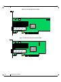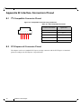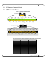
1
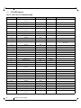
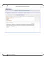
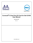
ConnectX®-2 Dual Port QSFP and SFP+
Adapter Card User Manual
P/N:
MHZH29-XTR, MHZH29-XSR, MHZH29B-XTR, MHZH29B-XSR
Rev 1.4
www.mellanox.com
Rev 1.4
NOTE:
THIS HARDWARE, SOFTWARE OR TEST SUITE PRODUCT (“PRODUCT(S)”) AND ITS RELATED DOCUMENTATION ARE
PROVIDED BY MELLANOX TECHNOLOGIES “AS-IS” WITH ALL FAULTS OF ANY KIND AND SOLELY FOR THE PURPOSE
OF AIDING THE CUSTOMER IN TESTING APPLICATIONS THAT USE THE PRODUCTS IN DESIGNATED SOLUTIONS. THE
CUSTOMER'S MANUFACTURING TEST ENVIRONMENT HAS NOT MET THE STANDARDS SET BY MELLANOX
TECHNOLOGIES TO FULLY QUALIFY THE PRODUCTO(S) AND/OR THE SYSTEM USING IT. THEREFORE, MELLANOX
TECHNOLOGIES CANNOT AND DOES NOT GUARANTEE OR WARRANT THAT THE PRODUCTS WILL OPERATE WITH THE
HIGHEST QUALITY. ANY EXPRESS OR IMPLIED WARRANTIES, INCLUDING, BUT NOT LIMITED TO, THE IMPLIED
WARRANTIES OF MERCHANTABILITY, FITNESS FOR A PARTICULAR PURPOSE AND NONINFRINGEMENT ARE
DISCLAIMED. IN NO EVENT SHALL MELLANOX BE LIABLE TO CUSTOMER OR ANY THIRD PARTIES FOR ANY DIRECT,
INDIRECT, SPECIAL, EXEMPLARY, OR CONSEQUENTIAL DAMAGES OF ANY KIND (INCLUDING, BUT NOT LIMITED TO,
PAYMENT FOR PROCUREMENT OF SUBSTITUTE GOODS OR SERVICES; LOSS OF USE, DATA, OR PROFITS; OR BUSINESS
INTERRUPTION) HOWEVER CAUSED AND ON ANY THEORY OF LIABILITY, WHETHER IN CONTRACT, STRICT LIABILITY,
OR TORT (INCLUDING NEGLIGENCE OR OTHERWISE) ARISING IN ANY WAY FROM THE USE OF THE PRODUCT(S) AND
RELATED DOCUMENTATION EVEN IF ADVISED OF THE POSSIBILITY OF SUCH DAMAGE.
Mellanox Technologies
350 Oakmead Parkway Suite 100
Sunnyvale, CA 94085
U.S.A.
www.mellanox.com
Tel: (408) 970-3400
Fax: (408) 970-3403
Mellanox Technologies, Ltd.
PO Box 586 Hermon Building
Yokneam 20692
Israel
Tel: +972-4-909-7200
Fax: +972-4-959-3245
© Copyright 2011. Mellanox Technologies. All rights reserved.
Mellanox®, BridgeX®, ConnectX®, InfiniBlast®, InfiniBridge®, InfiniHost®, InfiniRISC®, InfiniScale®, InfiniPCI®, PhyX® and
Virtual Protocol Interconnect® are registered trademarks of Mellanox Technologies, Ltd. CORE-Direct and FabricIT are trademarks of
Mellanox Technologies, Ltd. All other marks and names mentioned herein may be trademarks of their respective companies.
ConnectX-2 VPI Card User Manual
2
Mellanox Technologies
Document Number: 3157
ConnectX-2 VPI Card User Manual
Rev 1.4
Table of Contents
Table of Contents
3
List of Figures
5
List of Tables
6
Revision History
7
About this Manual
8
Intended Audience
Related Documentation
Online Resources
Document Conventions
Technical Support
Firmware and Software Updates
Chapter 1 Overview
1.1
1.2
1.3
1.4
Chapter 2
10
Adapter Cards Covered in this Manual
Mellanox Part Numbering Legend
Finding the GUID/MAC and Serial Number on the Adapter Cards
Safety Warnings
11
13
14
14
Adapter Card Interfaces
16
2.1
2.2
2.3
2.4
2.5
16
20
20
20
21
I/O Interfaces
Power
QSFP Power Level
Memory
VPD Layout
Chapter 3 Driver Software and Firmware
3.1
3.2
3.3
3.4
3.5
3.6
Chapter 4
8
8
8
8
8
9
Driver Software
FlexBoot
NVIDIA GPUDirect Support
CORE-Direct (Collectives Offload Resource Engine)
RDMA over Converged Ethernet (RoCE)
Updating Adapter Card Firmware
24
24
24
24
26
26
27
VPI Adapter Card Installation
29
4.1
4.2
4.3
4.4
29
29
30
35
Hardware and Software Requirements
Installation Instructions
Set Up
Cables and Modules
Appendix A Specifications
A.1
A.2
A.3
A.4
MHZH29B-X[ST]R Specifications
MHZH29-X[ST]R Specifications
Board Mechanical Drawing and Dimensions
EMC Certification Statements
Appendix B Interface Connectors Pinout
B.1
B.2
B.3
B.4
B.5
38
38
39
39
41
44
I2C-Compatible Connector Pinout
PCI Express x8 Connector Pinout
PCI Express Connector Pinout
QSFP Connector Pinout
SFP+ Connector Pinout
44
44
45
45
47
Appendix C Replacing a Tall Bracket With a Short Bracket
49
Mellanox Technologies
3
Rev 1.4
C.1 Remove the Existing Bracket from the Adapter Card
C.2 Installing the New Bracket
49
49
Appendix D Avertissements de sécurité d’installation (Warnings in French)
51
Appendix E Sicherheitshinweise (Warnings in German)
52
Appendix F Advertencias de seguridad para la instalación (Warnings in Spanish)
53
4
Mellanox Technologies
ConnectX-2 VPI Card User Manual
Rev 1.4
List of Figures
Figure 1:
Full Sized Component Side
12
Figure 2:
Small Form Factor Component Side
12
Figure 3:
Card Product Label
14
Figure 4:
Port Numbering
16
Figure 5:
LED - Port Association
19
Figure 6:
Physical and Logical Link Indications
19
Figure 7:
I2C Connector
20
Figure 8:
Flash Jumper
21
Figure 9:
Support Download Assistant
28
Figure 10: Hardware Devices
31
Figure 11: PCI Device
32
Figure 12: Module With Locking Mechanism Closed
36
Figure 13: Module With Locking Mechanism Open
36
Figure 14: Schematic of the ConnectX-2 MHZH29B Adapter Card
40
Figure 15: Schematic of the ConnectX-2 MHZH29 Adapter Card
41
Figure 16: Compatible Connector Plug and Pinout
44
Figure 17: Connector and Cage Views
45
Figure 18: Rear View of Module With Pin Placement
47
Figure 19: Remove the Bracket
49
Figure 20: Gasket Installation
50
Figure 21: Placing the Bracket on the Card
50
Mellanox Technologies
5
Rev 1.4
List of Tables
Table 1:
Revision History Table
7
Table 2:
Documents List
8
Table 3:
Adapter Cards List
11
Table 4:
Mellanox Cards Part Numbering Key
13
Table 5:
Supported Port Configurations
18
Table 6:
Unsupported Port Configurations
18
Table 7:
LEDs
19
Table 8:
Jumper Configuration
21
Table 9:
VPD Layout for MHZH29-X[ST]R
22
Table 10:
VPD Layout for MHZH29B-X[ST]R
23
Table 11:
Hardware and Software Requirements
29
Table 12:
Specifications for MHZH29-X[ST]R
38
Table 13:
Specifications for MHZH29-X[ST]R
39
Table 14:
Adapter Cards Certification Status
41
Table 15:
I2C-Compatible Connector Pinout
44
Table 16:
Connector Pin Name and Number to Signal Name Correspondence
45
Table 17:
SFP+ Connector Pinout
48
6
Mellanox Technologies
ConnectX-2 VPI Card User Manual
Rev 1.4
Revision History
This document was printed on 2/14/11.
Table 1 - Revision History Table
Date
Rev
Comments/Changes
Feb. 14th,
2011
1.4
July 22nd,
2010
1.3.4
Replaced Figure 1 photo of card with graphic
July 21st,
2010
1.3.3
Fixed TOC
Fixed Table 5
June 23rd,
2010
1.3.2
Minor formatting
May 13th,
2010
1.3.1
Minor formatting
April 2010
1.3
Replaced power numbers with the latest power numbers
Feb. 2010
1.2
Replaced power numbers with the latest power numbers
December
2009
1.1
Modified format
Added information to sections 5.4 Cables and Modules and 5.5 Cable Lengths
October
2009
1.0
Initial Release
Added the MHZH29B small form factor cards.
Updated Set up section
Mellanox Technologies
7
Rev 1.4
About this Manual
This User Manual describes Mellanox Technologies ConnectX®-2 Dual Port VPI InfiniBand and
Ethernet PCI Express x8 adapter cards. It provides details as to the interfaces of the board, specifications, required software and firmware for operating the board, and relevant documentation.
Intended Audience
This manual is intended for the installer and user of these cards.
The manual assumes basic familiarity with InfiniBand® and Ethernet networks and architecture
specifications.
Related Documentation
Table 2 - Documents List
Mellanox Firmware Tools (MFT) User Manual
Document no. 2204UG
User Manual describing the set of MFT firmware management tools for a
single node.
See http://www.mellanox.com => Firmware & Downloads => Download
Firmware Tools
Or
http://www.mellanox.com => Support => Download Firmware Tools
IBTA Specification Release 1.2.1
InfiniBand Architecture Specification
IEEE Std 802.3 Specification
This is the IEEE Ethernet specification
http://standards.ieee.org/getieee802
PCI Express 2.0 Specifications
Industry Standard PCI Express 2.0 Card Electromechanical Specification,
Rev 1.3.
Online Resources
• Mellanox Technologies Web pages: http://www.mellanox.com
• Mellanox Technologies Firmware download Web page:
http://www.mellanox.com => Support > Download Center
Document Conventions
When discussing memory sizes, MB and MBytes are used in this document to mean size in mega
bytes. The use of Mb or Mbits (small b) indicates size in mega bits.
Technical Support
Customers who purchased Mellanox products directly from Mellanox are invited to contact us
through the following methods.
8
Mellanox Technologies
ConnectX-2 VPI Card User Manual
Rev 1.4
• URL: http://www.mellanox.com => Support
• E-mail: [email protected]
• Tel: +1.408.916.0055
Customers who purchased Mellanox M-1 Global Support Services, please see your contract for
details regarding Technical Support.
Customers who purchased Mellanox products through a Mellanox approved reseller should first
seek assistance through their reseller.
Firmware and Software Updates
The Mellanox support downloader contains software, firmware and knowledge database information for Mellanox products. Access the data base from the Mellanox Support Web page,
http://www.mellanox.com=>Support
or use the following link to go directly to the Mellanox Support Download Assistant page,
http://www.mellanox.com/supportdownloader/.
Mellanox Technologies
9
Rev 1.4
1
Overview
Overview
This document is a User Manual for Mellanox Technologies network VPI adapter cards based on
MT25408 the ConnectX®-2 VPI integrated circuit device. The cards described in this manual have
the following main features:
• IEEE Std 802.3 compliant
• Virtual Protocol Interconnect IBTA v1.2.1 compliant
• SFP+ port for connecting Ethernet traffic
• Autosense for the running protocol and speed
• InfiniBand speeds: 10Gb/s (SDR), 20Gb/s (DDR), 40Gb/s (QDR)
• Ethernet speeds: 1Gb/s, 10 Gb/s
• Compliant with QSFP MSA spec Rev. 1.0
• Compatible with copper cables and optical cables with the use of QSFP connectors. Support for
SFP+ cables is available through QSA (Quad to Serial) adapters.
• CPU offload of transport operations
• CORE-Direct application offload
• GPU-Direct application offload
• End-to-end QoS and congestion control
• Hardware-based I/O virtualization
• TCP/UDP/IP stateless offload
• Fibre Channel encapsulation (FCoIB or FCoE)
• RoHS-R6
• PCI Express 2.0 (1.1 compatible) through an x8 edge connector up to 5GT/s
• Two bracket heights: short and tall
10
Mellanox Technologies
ConnectX-2 VPI Card User Manual
1.1
Rev 1.4
Adapter Cards Covered in this Manual
The MHZH29 card is a VPI adapter card with a 40Gb/s InfiniBand QSFP connector and a 10GigE
SFP+ connector.
The QSFP connector is compatible with InfiniBand Architecture Specifications
The SFP+ connector is compatible with 10GigE.
Table 3 lists the Single port VPI adapter cards described in this manual.
Table 3 - Adapter Cards List
Ordering Part
Number (OPN)
IB QSFP
Port Speed
ETH SFP+
Port Speed
Short /
Tall
Bracket
RoHS
Adapter IC
Part Number
MHZH29-XTR
40Gb/s (QDR)
10Gb/s
Tall
RoHS-R6
MT25408B0-FCCR-QI
MHZH29-XSR
40Gb/s (QDR)
10Gb/s
Short
RoHS-R6
MT25408B0-FCCR-QI
MHZH29B-XTR
40Gb/s (QDR)
10Gb/s
Tall
RoHS-R6
MT25408B0-FCCR-QI
MHZH29B-XSR
40Gb/s (QDR)
10Gb/s
Short
RoHS-R6
MT25408B0-FCCR-QI
Mellanox Technologies
11
Rev 1.4
Overview
Figure 1: Full Sized Component Side
J1
U1
Figure 2: Small Form Factor Component Side
J1
U1
12
Mellanox Technologies
ConnectX-2 VPI Card User Manual
1.2
Rev 1.4
Mellanox Part Numbering Legend
Table 4 describes the Mellanox Technologies adapter cards part numbering legend.
Table 4 - Mellanox Cards Part Numbering Key
Adapter Card
OPN
MHTS#I-XBR
Field
Decoder
M
Mellanox
Technologies
H
Adapter Type
H = InfiniBand Host Channel Adapter, N = Ethernet Network Interface Card
T
Media
Z = one SFP+ connector and one QSFP connector
S
Adapter
Architecture
H = ConnectX®or ConnectX-2
#
# ports
1 = 1, 2 = 2
I
Host Interface
X = PCI-X, 4 = PCIe x4, 8 = PCIe Gen1 x8, 9 = PCIe (Gen2 x8),
G
Generation
<blank> = Initial product generation, B= generation B, C= generation C
-
Separator
X
Memory Size
X = MemFree, 1=128MB, 2=256MB, 3=512MB
B
Bracket
S = Short, T = Tall, N = None
R
RoHS
<blank> = non RoHS, C = RoHS R-5 w/ Exemption, R = RoHS R-6 Lead-Free
For example, the part number MHZH29-XTR describes Mellanox Technologies’ ConnectX-2 card
with dual ports one SFP+ and one QSFP, a PCIe2.0 x8 5.0GT/s interface, no on-board memory
(mem-free), a tall PCI bracket, and RoHS R6 compliance. Using the legend,
• field M = M to indicate a Mellanox Technologies product,
• field H = H to indicate an InfiniBand Adapter Card,
• field T = Z to indicate 1 QSFP (IB QDR) port and 1 SFP+ (10GigE) port,
• field S = H to indicate the ConnectX family,
• field # = 2 to indicate two ports,
• field I = 9 to indicate PCI Express 2.0 x8 running at 5.0GT/s,
• field X = X to indicate no on-board memory,
• field B = T to indicate a tall bracket, and
• field R = R to indicate RoHS R6 (lead free) compliance
Mellanox Technologies
13
Rev 1.4
1.3
Overview
Finding the GUID/MAC and Serial Number on the Adapter Cards
All Mellanox adapter cards have a label on the printed side of the adapter card that has the card
serial number, the card MAC for Ethernet protocol, and the card GUID for InfiniBand protocol
VPI Cards have both a MAC and a GUID. For VPI cards the MAC is derived from the GUID.
Figure 3: Card Product Label
S/N:MT0744X00012
REV: X1
P/N:MHZH29-XTR
GUID: 0002C9030005646 C
M AC: 0002C901122642 FC
Made in IL
Port 1 uses the GUID or MAC ID described on the label, for port 2 GUID or MAC add
1 to port 1's description.
1.4
Safety Warnings
For safety warnings in French see “Avertissements de sécurité d’installation (Warnings in French)”
on page 51. For safety warnings in German see “Sicherheitshinweise (Warnings in German)” on
page 52. For safety warnings in Spanish see “Advertencias de seguridad para la instalación (Warnings in Spanish)” on page 53.
1. Installation Instructions
Read all installation instructions before connecting the equipment to the power source.
2. Over-temperature
This equipment should not be operated in an area with an ambient temperature exceeding the maximum recommended: 55°C (131°F).
To guarantee proper air flow, allow at least 8cm (3 inches) of clearance around the ventilation openings.
14
Mellanox Technologies
ConnectX-2 VPI Card User Manual
Rev 1.4
3. During Lightning - Electrical Hazard
During periods of lightning activity, do not work on the equipment or connect or disconnect cables.
4. Copper Cable Connecting/Disconnecting
Some copper cables are heavy and not flexible, as such they should be carefully
attached to or detached from the connectors. Refer to the cable manufacturer for special warnings and instructions.
5. Equipment Installation
This equipment should be installed, replaced, or serviced only by trained and qualified
personnel.
6. Equipment Disposal
Disposal of this equipment should be in accordance to all national laws and regulations.
7. Local and National Electrical Codes
This equipment should be installed in compliance with local and national electrical
codes.
Mellanox Technologies
15
Rev 1.4
Adapter Card Interfaces
2
Adapter Card Interfaces
2.1
I/O Interfaces
Each adapter card includes the following interfaces:
• QSFP port
• SFP+ port
• PCI Express x8 edge connector
• I/O panel LEDs
• I2C compatible connector (for debug)
Port 1 connects to the InfiniBand port of the device, while port 2 connects to the Ethernet port of
the device.
Figure 4: Port Numbering
Port 1
QSFP
Port 2
SFP+
2.1.1 InfiniBand Interface
The ConnectX®-2 device is compliant with the InfiniBand Architecture Specification, Release 1.2.1.
VPI adapter cards (listed in Table 3) based on this device provide access to its ports by means of
QSFP connectors.
2.1.2 Ethernet SFP+ Interface
The ConnectX®-2 device is compliant with the IEEE Std 802.3. The SFP+ port has one Tx/Rx pair
of SerDes. VPI adapter cards listed in Table 3 on page 11 based on this device provide access to
the Ethernet ports by means of SFP+ and QSFP connectors. The Mellanox QSA (QSFP to SFP +)
adapter modules can be ordered through Mellanox Technologies authorized dealers.
16
Mellanox Technologies
ConnectX-2 VPI Card User Manual
Rev 1.4
2.1.3 VPI Port Configuration
VPI ports are auto-sensing but can be manually configured using a script.
Port type management:
By default ConnectX® -2 ports are initialized as Infiniband ports. If you wish to change the port
type use the connectx_port_config script after the driver is loaded.
The script is installed as part of the Mellanox OFED for Linux package (under /sbin). See the Mellanox OFED for Linux User’s Manual available at http://www.mellanox.com =>Support > InfiniBand Software and Drivers > Mellanox OFED.
Running "/sbin/connectx_port_config -s" will show the current port configuration for all ConnectX® -2 devices.
Port configuration is saved in the file: /etc/infiniband/connectx.conf. This saved configuration is
restored at driver restart only if done via "/etc/init.d/openibd restart".
Possible port types are:
• "eth" - Always Ethernet
• "ib" - Always Infiniband
• "auto" - Link sensing mode - detect port type based on the attached network type. If no link is
detected, the driver retries link sensing every few seconds.
The port link type can be configured for each device in the system at run time using the "/sbin/
connectx_port_config" script. This utility will prompt for the PCI device to be modified (if there is
only one it will be selected automatically). At the next stage the user will be prompted for the
desired mode for each port.
The desired port configuration will then be set for the selected device. Note: This utility also has a
non interactive mode:
"/sbin/connectx_port_config [[-d|--device <PCI device ID>] -c|--conf <port1,port2>]".
Mellanox Technologies
17
Rev 1.4
Adapter Card Interfaces
The following configurations are supported by dual port VPI:
Table 5 - Supported Port Configurations
Port 1
Port 2
Ethernet
Ethernet
IB
IB
auto-sensing
auto-sensing
IB
Ethernet
IB
auto-sensing
auto-sensing
Ethernet
The following options are not supported by dual port VPI:
Table 6 - Unsupported Port Configurations
Port 1
Port 2
Ethernet
IB
Ethernet
auto-sensing
auto-sensing
IB
2.1.4 PCI Express Interface
The ConnectX®-2 adapter cards support PCI Express 2.0 (1.1 compatible) through an x8 edge connector. The device can be either a master initiating the PCI Express bus operations or a slave
responding to PCI bus operations.
2.1.5 LED Assignment
The board has I/O LEDs located on the I/O panel. The green LED, when lit, indicates that the
driver is running and a valid physical connection between nodes exists. If the green LED is blinking, it indicates a problem with the physical link. The yellow LED when lit, indicates a valid data
activity link, this is the logical link. The yellow LED lights up when the network is discovered
over the physical link. A valid data activity link without data transfer is designated by a constant
yellow LED indication. A valid data activity link with data transfer is designated by a blinking yellow LED indication. If the LEDs are not active, either the physical link or the logical link (or both)
connections have not been established.
18
Mellanox Technologies
ConnectX-2 VPI Card User Manual
Rev 1.4
Figure 5: LED - Port Association
Port 1
Port 2
Figure 6: Physical and Logical Link Indications
Table 7 - LEDs
Port Number
LED Name
Port 1
Physical Link - Green
Constant on indicates a good physical link
Blinking indicates a problem with the Physical
link
Port 1
Data Activity - Yellow
Blinking indicates Data Transfer
Constant on indicates no Data Transfer
Port 2
Physical Link - Green
Constant on indicates a good physical link
Blinking indicates a problem with the Physical
link
Port 2
Data Activity - Yellow
Blinking indicates Data Transfer
Constant on indicates no Data Transfer
The short bracket has the same port and LED footprint as the tall bracket.
Mellanox Technologies
19
Rev 1.4
Adapter Card Interfaces
2.1.6 I2C Compatible Interface
A three-pin header on the adapter card is provided as the I2C compatible interface. See
Appendix A,“Specifications,” on page 38 for the location on the board.
Figure 7: I2C Connector
2.2
Power
All adapter cards receive 12V and 3.3V power from the PCI Express Edge connector. All other
required power voltages are generated by on-board switch mode regulators. See “Specifications”
on page 38.
2.3
QSFP Power Level
The card supports power level 3, according to SFF Committee SFF-8436 Specification for QSFP
(Quad Small Formfactor Pluggable) Transceiver.
2.4
Memory
The adapter cards support multiple memory devices through the PCI Flash, and I2C.
2.4.1 System Memory
The adapter card utilizes the PCI Express interface to store and access IB fabric and/or Ethernet
fabric connection information and packet data on the system memory.
2.4.2 Flash
Each of the adapter cards include one 16MB SPI Flash device M25P16-VME6G device by ST
Microelectronics) accessible via the Flash interface of the MT25408B0 ConnectX®-2 VPI device.
There is a jumper on each adapter card that indicates to the device whether an on-board Flash
device is to be used. Table 8 provides information on this jumper. See the schematic in
Appendix A,“Specifications,” on page 38 for the jumper location.
20
Mellanox Technologies
ConnectX-2 VPI Card User Manual
Rev 1.4
Table 8 - Jumper Configuration
Description
Flash present/
not present
Option
connection open – Flash present
connection shorted – Flash not present
Card Default
Configuration
connection open –
Flash present
Comments
Header 1x2
Figure 8: Flash Jumper
2.4.3 EEPROM
Each board incorporates an EEPROM that is accessible through the I2C. The EEPROM is used for
storing the Vital Product Data (VPD). The EEPROM capacity is 4Kb.
2.5
VPD Layout
The PCI VPD (Vital Product Data) layout, for each of the described Mellanox Technologies ConnectX®-2 VPI adapter cards complies with the format defined in the PCI 2.3 Specification, Appendix I. All ConnectX-2® adapter cards have the same PCI VPD layout.
Mellanox Technologies
21
Rev 1.4
2.5.1
Adapter Card Interfaces
PCI VPD Layout
Table 9 - VPD Layout for MHZH29-X[ST]R
Offset (Decimal)
Item
Value
0
Large Resource Type ID String Tag
(0x02)
0x82
1
Length [7:0] LSB
0x6
2
Length [15:8] MSB
0x0
3
Data
RAPTOR
9
Large Resource Type VPD-R Tag
(0x10)
0x90
10
Length [7:0] LSB
0x4F
11
Length [15:8] MSB
0x00
12
VPD Keyword
PN
14
Length
0x15
15
PN
PN
%STR_SPC
36
VPD Keyword
EC
STR
Engineering Change Level of the
card (rev)
38
Length
0x2
39
Revision
RV
%STR
PCB revision
41
VPD Keyword
SN
STR
Serial Number
43
Length
0x18
%STR_SPC
“00..00XXXX..XX”
STR
Misc Information
22
Format
Description
STR
STR
Add in Card Part Number
44
SerialNumber
68
VPD Keyword
V0
70
Length
0x10
71
Data
PCIe Gen2 x8
STR_SPC
87
VPD Keyword
RV
STR
89
Length
0x1
90
Data
0,89
91
Large Resource Type VPD-W Tag
(0x11)
0x91
92
Length [7:0] LSB
0xA1
93
Length [15:8] MSB
0x00
94
VPD Keyword
V1
96
Length
0x6
97
Data
N/A
STR_SPC
103
VPD Keyword
YA
STR
105
Length
0x20
106
Data
N/A
STR_SPC
“N/A”
138
VPD Keyword
RW
STR
Remaining read/write area
140
Length
0x72
141
Data
STR_ZERO
Reserved (0x00)
255
Small Resource Type END Tag
(0x11)
Mellanox Technologies
0x78
%CS0
STR
EFI Driver version
Asset Tag
ConnectX-2 VPI Card User Manual
Rev 1.4
Table 10 - VPD Layout for MHZH29B-X[ST]R
Offset (Decimal)
Item
Value
Format
Description
0
Large Resource Type ID String Tag
(0x02)
0x82
1
Length [7:0] LSB
0x6
2
Length [15:8] MSB
0x0
3
Data
RAPTOR
9
Large Resource Type VPD-R Tag
(0x10)
0x90
10
Length [7:0] LSB
0x4F
11
Length [15:8] MSB
0x00
12
VPD Keyword
PN
14
Length
0x15
15
PN
PN
%STR_SPC
36
VPD Keyword
EC
STR
38
Length
0x2
39
Revision
RV
%STR
PCB revision
41
VPD Keyword
SN
STR
Serial Number
43
Length
0x18
44
SerialNumber
%STR_SPC
“00..00XXXX..XX”
68
VPD Keyword
V0
STR
Misc Information
70
Length
0x10
71
Data
PCIe Gen2 x8
STR_SPC
87
VPD Keyword
RV
STR
89
Length
0x1
90
Data
0,89
91
Large Resource Type VPD-W Tag
(0x11)
0x91
92
Length [7:0] LSB
0xA1
93
Length [15:8] MSB
0x00
94
VPD Keyword
V1
96
Length
0x6
STR
STR
Add in Card Part Number
Engineering Change Level of the card
(rev)
%CS0
STR
EFI Driver version
97
Data
N/A
STR_SPC
103
VPD Keyword
YA
STR
Asset Tag
105
Length
0x20
106
Data
N/A
STR_SPC
“N/A”
138
VPD Keyword
RW
STR
Remaining read/write area
140
Length
0x72
STR_ZERO
Reserved (0x00)
141
Data
255
Small Resource Type END Tag (0x11)
0x78
Mellanox Technologies
23
Rev 1.4
Driver Software and Firmware
3
Driver Software and Firmware
3.1
Driver Software
3.1.1 Linux
For Linux, download and install the latest OpenFabrics Enterprise Distribution (OFED) software
package available via the Mellanox Web site at:
http://www.mellanox.com => Support > Download Center. Follow the installation instructions
included in the download package.
3.1.2 Windows
Support > Download Center.For Windows, there are currently two distinct packages:
• MLNX EN – Ethernet driver
• MLNX WinOF – IB driver
These packages cannot co-exist (you need to uninstall one of them before installing the other).
Soon we will release a VPI package that will support both IB and Ethernet.
• Download these two packages from the Mellanox Web site at:
For IB: http://www.mellanox.com => Downloads => InfiniBand/VPI SW/Drivers
• For Eth: http://www.mellanox.com => Downloads => Ethernet SW/Drivers
Follow the installation instructions included in the download package.
3.2
FlexBoot
FlexBoot enables remote boot over Ethernet or InfiniBand using Boot over InfiniBand (BoIB),
Boot over Ethernet (BoE), or Boot over iSCSI (Bo-iSCSI). This technology is based on the Preboot Execution Environment (PXE) standard specification, and FlexBoot software is based on the
open source EtherBoot/gPXE project (see www.etherboot.org). For more information go to
http://www.mellanox.com => Support > Download Center.
3.3
NVIDIA GPUDirect Support
Utilizing the high computational power of the Graphics Processing Unit (GPU), the GPU-to-GPU
method has proven valuable in various areas of science and technology. Mellanox ConnectX-2
based HCA provides the required high throughput and low latency for GPU-to-GPU communications.
3.3.1 Hardware and Software Requirements
Software:
Operating Systems:
24
Mellanox Technologies
ConnectX-2 VPI Card User Manual
Rev 1.4
• RHEL5.4 2.6.18-164.el5 x86_64 or later
• Mellanox OFED with GPUDirect support
• NVIDIA Development Driver for Linux version 195.36.15 or later
Hardware:
• Mellanox ConnectX-2 HCA card
• NVIDIA Tesla series
3.3.2 Installation
For installation instructions visit: www.mellanox.com => Support => VPI SW/Driver.
3.3.2.1 Kernel Installation:
Use Red Hat Package Manager (RPM) to install the Kernel RPM files:
- Install the required RPMs, for example, run:
# rpm --force -ivh *.rpm
- Modify the boot loader configuration file if needed
(e.g., edit /etc/grub.conf)
- Reboot the machine with the new kernel
# reboot
3.3.2.2 MLNX OFED Drivers Installation:
The MLNX driver is called MLNX_OFED_LINUX-Nvidia-1.5.1.
- Mount the ISO file:
# mount -o ro, loop MLNX_OFED_<version>.iso /mnt
- Run the installation script:
# /mnt/mlnxofed install
- Restart the driver:
# /etc/init.d/openibd restart
- To make sure that GPUDirect is enabled, run:
# cat /sys/module/ib_core/parameters/gpu_direct_enable => 1
The number of shared pages by GPUDirect is reported under:
# cat /sys/module/ib_core/parameters/gpu_direct_shares
3.3.2.3 NVIDIA Driver Installation:
Install NVIDIA Development Driver for Linux x86_64, available under:
http://developer.nvidia.com/object/cuda_3_0_downloads.html
For example:
- Run: devdriver_3.0_linux_64_195.36.15.run
- Follow the installation wizard instructions
To make sure that the NVIDIA driver was installed successfully:
- Load nvidia driver:
# modprobe nvidia
Mellanox Technologies
25
Rev 1.4
Driver Software and Firmware
- Check the driver version, for example:
# cat /proc/driver/nvidia/version => version 195.36.15 (or later)
3.4
CORE-Direct (Collectives Offload Resource Engine)
CORE-Direct (Collectives Offload Resource Engine) provides the most advanced solution for
handling collectives operations, ensures maximum scalability, minimizes the CPU overhead and
provides the capability for overlapping communications with computations. Mellanox ConnectX®-2 adapters address the collectives communication scalability problems by offloading the
communications to the adapters and switches.
3.4.1 Hardware and Software Requirements
Software:
Operating system
•
RHEL 5.4 or later
•
Mellanox OFED 1.5.1 or later
Hardware:
•
Mellanox ConnectX®-2 HCA card
•
Disk Space for Installation 400 MB
3.4.2 Installation
For installation instructions visit: www.mellanox.com => Support => VPI SW/Driver
3.5
RDMA over Converged Ethernet (RoCE)
ConnectX-2 with RoCE utilizes advances in Data Center Bridging (DCB) to enable efficient and
low cost implementations of RDMA over Ethernet, supporting the entire breadth of RDMA and
low latency features. This includes reliable connected service, datagram service, RDMA and send/
receive semantics, atomic operations, user level multicast, user level I/O access, kernel bypass,
and zero copy.
ConnectX-2 with RoCE based network management is the same as that for any Ethernet and DCBbased network management, eliminating the need for IT managers to learn new technologies.
3.5.1 Hardware and Software Requirements
Software:
Operating System
•
Mellanox OFED 1.5.1 or later
Hardware:
•
ConnectX-2 Adapter Card
To use RoCE you will need the following versions of firmware and software:
26
Mellanox Technologies
ConnectX-2 VPI Card User Manual
Rev 1.4
• OFED 1.5.1 or later
• firmware version 2.7.700 or later
3.5.2 Installation
For installation instructions visit: www.mellanox.com => Support => Ethernet SW/Driver
3.6
Updating Adapter Card Firmware
Each card is shipped with the latest version of qualified firmware at the time of manufacturing.
Firmware is updated occasionally, and the most recent firmware can be obtained from:
http://www.mellanox.com =>Support > Download Center. Check that the firmware on your card is
the latest found on the Mellanox site, if not update to the latest version found on the Mellanox
website.
Firmware can be updated on the stand alone single card using the flint tool of the Mellanox Firmware Tools (MFT) package. This package is available for download, along with its user manual,
from the Mellanox Firmware Tools page. See http://www.mellanox.com => Support > Download
Center.
A firmware binaries table lists a binary file per adapter card. The file name of each such binary is
composed by combining the firmware name, the firmware release version, and the card part number. Please contact Mellanox sysem support if you cannot find the firmware binary for your
adapter card.
To check the latest firmware:
1. Go to Mellanox web site to check current firmware version.
Go to: http://www.mellanox.com/supportdownloader
2. Enter your card PSID and compare the firmware versions.
Mellanox Technologies
27
Rev 1.4
Driver Software and Firmware
Figure 9: Support Download Assistant
28
Mellanox Technologies
ConnectX-2 VPI Card User Manual
Rev 1.4
4
VPI Adapter Card Installation
4.1
Hardware and Software Requirements
Before installing the adapter card, please make sure that the system meets the hardware and software requirements listed in Table 11. Refer to Chapter 3,“Driver Software and Firmware” on
page 24 for download and installation instructions.
Table 11 - Hardware and Software Requirements
Requirement
Description
Hardware
•
PCI Express x8 or x16 slots
Software
Operating
Systems/Distributions
•
For Windows, both the InfiniBand and Ethernet drivers are in the Mellanox WinOF
for Windows software package available via Mellanox Web site http://www.mellanox.com => Downloads > Mellanox WinOF VPI for Windows
For Linux, both the InfiniBand and Ethernet drivers are in the Mellanox OpenFabrics Enterprise Distribution (OFED) software package available via the Mellanox
Web site
http://www.mellanox.com => Downloads > InfiniBand/VPI SW/ Linux Drivers
•
4.2
Installation Instructions
To change a tall bracket to a short bracket see Replacing a Tall Bracket With a Short Bracket on
page 49.
Read all installation instructions before connecting the equipment to the power source.
The adapter cards listed in Table 3 on page 11 are standard PCI Express cards, each with a standard x8 edge connector. Please consult the host machine documentation for instructions on how to
install a PCI Express card.
When more than one PCI slot is available make sure to use the PCI slot with the proper
configuration.
Any PCI slot with the proper configuration is acceptable for connection. If the card is installed in a
PCI slot with less lanes than the card requires then the adapter card will not provide the optimum
data transfer.
Mellanox Technologies
29
Rev 1.4
4.3
VPI Adapter Card Installation
Set Up
This section is valid for InfiniBand, Ethernet and VPI cards. Disregard sections that are
not relevant to your card.
The basic steps to embed Mellanox cards in your computer are:
1. Identify the card in your system.
2. Verify the computer is recognizing the new adapter.
3. Install the adapter drivers.
4. Update the adapter firmware if needed.
The configuration of the card is dependant upon your choice to use InfiniBand or Ethernet.
4.3.1 Identify the Card in Your System
For instructions to identify your adapter card using specific tools see
http://www.mellanox.com/content/pages.php?pg=firmware_HCA_FW_identification
Otherwise, use the instructions below relevant to your particular card and OS.
4.3.1.1 Windows
1. Open Device Manager. Click start--> Run, and then enter “devmgmt.msc”.
2. Check the Device Manager under “Other devices” for “PCI Device” (Windows 2003) or
“InfiniBand Controller” (Windows 2008/R2).
If you cannot find any PCI device, click Action --> Scan for hardware changes. If no
PCI devices are detected, check that the network adapter card(s) is correctly installed in
the PCI slot or try installing the adapter card into a different PCI slot.
30
Mellanox Technologies
ConnectX-2 VPI Card User Manual
Rev 1.4
Figure 10: Hardware Devices
3. Select a PCI Device / InfiniBand Controller entry.
4. Right-click.
5. Select “Properties to display the PCI Device Properties” window.
6. Click the Details tab and select Device Instance Id (Windows 2003) or
Hardware Ids (Windows 2008/R2) from the Property pull-down menu.
Mellanox Technologies
31
Rev 1.4
VPI Adapter Card Installation
Figure 11: PCI Device
7. In the Value display box, check the fields VEN and DEV (fields are separated by ‘&’). In the
display example above, notice the sub-string “PCI\VEN_15B3&DEV_6368”: VEN is equal to
0x15B3 – this is the Vendor ID of Mellanox Technologies; and DEV is equal to 0x6368 – this is
a valid Mellanox Technologies PCI Device ID.
The list of Mellanox Technologies PCI Device IDs can be found in the PCI ID repository at http://pci-ids.ucw.cz/read/PC/15b3.
8. If the PCI device does not have a Mellanox adapter ID, return to Step 3 to check another device.
32
Mellanox Technologies
ConnectX-2 VPI Card User Manual
Rev 1.4
4.3.1.2 Linux
Get the device location on the PCI bus by running lspci and locating lines with the string “Mellanox Technologies”:
> lspci
| grep Mellanox
2:00.0 InfiniBand: Mellanox Technologies MT26428 [ConnectX VPI PCIe
2.0 5GT/s - IB QDR / 10GigE] (rev b0)
Make sure that either the MLNX_OFED driver or the MLNX_EN driver is loaded and configured.
Check the link status
First check the network interface name by running the “ifconfig –a” command.
To check the Ethernet link status, for EN only and VPI cards, run: ethtool <interface>
Host# ethtool eth1
Supported ports: [ TP ]
Supported link modes:
10baseT/Half 10baseT/Full
100baseT/Half 100baseT/Full
1000baseT/Half 1000baseT/Full
Supports auto-negotiation: Yes
Advertised link modes: 10baseT/Half 10baseT/Full
100baseT/Half 100baseT/Full
1000baseT/Half 1000baseT/Full
Advertised auto-negotiation: Yes
Speed: Unknown! (0)
Duplex: Half
Port: Twisted Pair
PHYAD: 1
Transceiver: internal
Auto-negotiation: on
Supports Wake-on: g
Wake-on: d
Current message level: 0x000000ff (255)
Link detected: yes
To check the IB link status, for IB anad VPI cards, run “ibstat” and focus on the Physical state
attributes.
Example:
Host# ibstat
CA 'mlx4_0'
CA type: MT26428
Number of ports: 1
Firmware version: 2.7.616
Hardware version: b0
Node GUID: 0x0002c903000c8710
System image GUID: 0x0002c903000c8713
Port 1:
State: Down
Physical state: Polling
Mellanox Technologies
33
Rev 1.4
VPI Adapter Card Installation
Rate: 10
Base lid: 6
LMC: 0
SM lid: 3
Capability mask: 0x0251086a
Port GUID: 0x0002c903000c8711
Link layer: IB
Check the OFED version
To get the version of the running Mellanox OFED/BXOFED, run the following command:
Host# ofed_info | head -1
BXOFED-1.5.1-1.3.7-rc19:
Troubleshooting MLNX_OFED Installation
For troubleshooting driver installation, please check Mellanox OFED driver user manual:
http://www.mellanox.com => Support > Adapter IB/VPI SW.
If you need to update your card firmware, download the new firmware.
Unzip the downloaded file and run flint/mstflint command:
flint -d <device> -i <fw-file> [-guid <GUID> | -guids <4 GUIDS> | -mac <MAC> | -macs <2 MACs>] burn
Check VPI setup – Ethernet / InfiniBand configuration
For Example:
flint
-d /dev/mst/mt26428_pci_cr0 –i fw-25408-2_7_000-MNPH28B-XTC_A1-A2.bin burn
Loading the Ethernet Driver
By default, the Mellanox OFED stack loads mlx4_en. Run ‘lsmod’ to verify that the module is
listed.
Example:
Host# lsmod | grep mlx4_en
mlx4_en
109708
mlx4_core
136804
0
2 mlx4_en,mlx4_ib
If you don’t see the mlx4_en driver, run: ’ modprobe mlx4_en’
Another option is to use the command below to see which modules are active.
Edit ”/etc/infiniband/openib.conf” which modules needs to loaded from a service.
For example:
# Load MLX4_EN module
MLX4_EN_LOAD=yes
34
Mellanox Technologies
ConnectX-2 VPI Card User Manual
Rev 1.4
The “Usage: openibd {start|stop|restart|status}” command to modify this file and thereby control
the drivers.
Ethernet Driver Usage and Configuration
To assign an IP address to the interface run:
#> ifconfig eth<n> <ip>
where 'n' is the OS assigned interface number.
• To check driver and device information run:
#> ethtool -i eth<n>
Example:
#> ethtool -i eth2
driver: mlx4_en (MT_04A0140005)
version: 1.5.1 (March 2010)
firmware-version: 2.7.000
bus-info: 0000:13:00.0
• The mlx4_en parameters can be found under /sys/module/mlx4_en (or /sys/module/mlx4_en/
parameters, depending on the OS) and can be listed using the command:
#> modinfo mlx4_en
To set non-default values to module parameters, the following line should be added to the file/etc/
modprobe.conf:
"options mlx4_en <param_name>=<value> <param_name>=<value> ..."
Ethernet Network Tuning
To improve network perfomance by tuning your network see the Mellanox Performance Tuning
Guide located at:
http://www.mellanox.com/related-docs/prod_software/
Performance_Tuning_Guide_for_Mellanox_Network_Adapters_rev_1_0.pdf
4.4
Cables and Modules
Mellanox QSFP ports can connect to InfiniBand passive copper cables, active copper cables and
optical cables using direct attach cables and through QSFP modules. These ports can connect to
hybrid QSFP to SFP+ cables.
The SFP+ port can connect to the Ethernet through both direct attach cables and stand alone transceivers with optical cables. SFP+ transceiver modules are available for both SR and LR protocols.
See www.mellanox.com => Products => Cables for certified and approved cable recommendations.
Mellanox Technologies
35
Rev 1.4
VPI Adapter Card Installation
4.4.1 Optical modules for SFP+
SFP+ transceiver modules can be used to connect fiber optic cables to the cards greatly increasing
the cable reach.
The adapter cards are shipped without optical modules. Mellanox 10GBASE-SR (MFM1T02ASR) and 10GBASE-LR (MFM1T02A-LR) optical modules are recommended. The figure below
shows the Mellanox SFP+ module.
Inserting the Optical Transceiver Module
To insert the module into the cage:
1. Open the module’s locking mechanism – see Figure 12 and Figure 13.
2. Make sure that the male connector on the module will align with the female connector inside of
the cage. Also check that there is no dirt or foreign matter in the module or in the cage.
Figure 12: Module With Locking Mechanism Closed
Figure 13: Module With Locking Mechanism Open
3. Insert the module into the adapter card module cage.
4. Close the locking Mechanism.
To remove the module from the cage:
1. Unlock the locking mechanism by opening the handle.
2. Pull the module out of the cage.
4.4.2 Optical Modules for QSFP
These cards support optical modules for active fiber optical cables. The part ordering number for
this module is MFM4R12C-QDR.
4.4.3 Modules for QSFP to SFP+
These cards support modules for SFP+ cables. The Quad to Single Small Form Factor Pluggable
adapter (QSFP to SFP+ adapter or QSA) is built in QSFP form factor with a receptacle for SFP+
cable connector. The part ordering number for this module is MAM1Q00A-QSA.
36
Mellanox Technologies
ConnectX-2 VPI Card User Manual
Rev 1.4
4.4.4 Cable Installation
All cables can be inserted or removed with the unit powered on. To insert a cable, press the connector into the port receptacle until the connector is firmly seated. The GREEN LED indicator will
light when the physical connection is established (that is, when the unit is powered on and a cable
is plugged into the port with the other end of the connector plugged into a functioning port). After
plugging in a cable, lock the connector using the latching mechanism particular to the cable vendor. When a logical connection is made the YELLOW LED will come on. When data is being
transferred the yellow led will blink.
When installing cables make sure that the latches engage.
Always install and remove cables by pushing or pulling the cable and connector in a
straight line with the card.
Care should be taken not to impede the air exhaust flow through the ventilation holes. Cable
lengths should be used which allow for routing horizontally around to the side of the chassis before
bending upward or downward in the rack.
To remove a cable, disengage the locks and slowly pull the connector away from the port receptacle. Both LED indicators will turn off when the cable is unseated.
Cables, especially long copper cables, can weigh a substantial amount. Make sure that
the weight of the cable is supported on its own and is not hanging from the adapter
card.
Mellanox Cards support up to 40 Gb/s IB over the QSFP port, and up to 10Gb/s on the SFP+ connector.
4.4.5 InfiniBand Connectivity
These Mellanox Cards support QSFP passive and active copper and active optical cables.
Mellanox Technologies
37
Rev 1.4
Appendix A: Specifications
A.1
MHZH29B-X[ST]R Specifications
Table 12 - Specifications for MHZH29-X[ST]R
Physical
Power and Environmental
Size:
Air Flow:
QSFP40Gb/s
Connector:
SFP+ Connector:
2.71in. x6.60in. (68.90mm x
167.65mm)
InfiniBand (Copper and optical)
Max power per port 2.0 W.
Cable power budget class 2
Maximum Power:
8.66W for passive cables only
11.36W for active optic modules
Temperature:
0°C to 55°C
Regulatory
IBTA v1.2.1, Auto-Negotiationb
(40Gb/s, 10Gb/s per lane), (20Gb/s,
5Gb/s per lane) or (10Gb/s, 2.5Gb/s
per lane)
Ethernet:
IEEE Std 802.3ae 10 Gigabit Ethernet
IEEE Std 802.3ad Link Aggregation
and Failover
IEEE Std 802.3x Pause
IEEE Std 802.1Q VLAN tags
IEEE Std 802.1p Priorities
Multicast
Jumbo frame support (10KB)
128 MAC/VLAN addresses per port
8 Virtual Lanes for InfiniBand
8 Priority Queues for Ethernet
EMC:
Environmental:
RoHS:
FCC 47 CFR part 15:2006, subpart
B, class A
ICES-003:2004 Issue 4, class A
VCCI V-3/2007.04, class A
EN 55022:1998+A1:
2000+A2:2003 class A,
EN 61000-3-2:2000+A2:2005,
EN61000-3-3:1995+A2:2005,
EN 55024:1998 + A1:2001+A2:2003
standards, harmonized under EMC
Directive 2004/108/EC Article 6(2);
AS/NZS 3548
IEC/EN 60950-1:2006
ETSI EN 300 019-2-2
IEC 60068-2- 64, 29, 32
RoHS-R6
Yes, All Ports
Data Rate
SFP+ Ethernet:
10 Gb/s
QSFP InfiniBand:
40 Gb/s
PCI Express:
8.01W for passive cables only
10.71W for active optic modules
Ethernet (Copper and optical)
Max power per port 0.7W
InfiniBand:
RDMA Support:
12V, 3.3V
Typ Power:
200LFMa
Protocol Support
QoS:
Voltage:
2.0 SERDES @ 5.0 GT/s
a. Air flow is measured ~1” from the heat sink between the heat sink and the cooling air inlet.
b. The auto-negotiation protocol is proprietary of Mellanox Technologies and compliant with the InfiniBand Architecture Specification, Release 1.2.
38
Mellanox Technologies
ConnectX-2 VPI Card User Manual
A.2
Rev 1.4
MHZH29-X[ST]R Specifications
Table 13 - Specifications for MHZH29-X[ST]R
Physical
Power and Environmental
Size:
Air Flow:
QSFP40Gb/s
Connector:
SFP+ Connector
2.71in. x6.60in. (68.90mm x
167.65mm)
InfiniBand (Copper and optical)
Max power per port 2.0 W.
Cable power budget class 2
Maximum Power:
8.66W for passive cables only
11.36W for active optic modules
Temperature:
0°C to 55°C
Regulatory
IBTA v1.2.1, Auto-Negotiationb
(40Gb/s, 10Gb/s per lane), (20Gb/s,
5Gb/s per lane) or (10Gb/s, 2.5Gb/s
per lane)
Ethernet:
IEEE Std 802.3ae 10 Gigabit Ethernet
IEEE Std 802.3ad Link Aggregation
and Failover
IEEE Std 802.3x Pause
IEEE Std 802.1Q VLAN tags
IEEE Std 802.1p Priorities
Multicast
Jumbo frame support (10KB)
128 MAC/VLAN addresses per port
EMC:
Environmental:
8 Virtual Lanes for InfiniBand
8 Priority Queues for Ethernet
RoHS:
FCC 47 CFR part 15:2006, subpart
B, class A
ICES-003:2004 Issue 4, class A
VCCI V-3/2007.04, class A
EN 55022:1998+A1:
2000+A2:2003 class A,
EN 61000-3-2:2000+A2:2005,
EN61000-3-3:1995+A2:2005,
EN 55024:1998 + A1:2001+A2:2003
standards, harmonized under EMC
Directive 2004/108/EC Article 6(2);
AS/NZS 3548
IEC/EN 60950-1:2006
ETSI EN 300 019-2-2
IEC 60068-2- 64, 29, 32
RoHS-R6
Yes, All Ports
Data Rate
SFP+ Ethernet:
10 Gb/s
QSFP InfiniBand:
40 Gb/s
PCI Express:
8.01W for passive cables only
10.71W for active optic modules
Ethernet (Copper and optical)
Max power per port 0.7W
InfiniBand:
RDMA Support:
12V, 3.3V
Typ Power:
200LFMa
Protocol Support
QoS:
Voltage:
2.0 SERDES @ 5.0 GT/s
a. Air flow is measured ~1” from the heat sink between the heat sink and the cooling air inlet.
b. The auto-negotiation protocol is proprietary of Mellanox Technologies and compliant with the InfiniBand Architecture Specification, Release 1.2.
A.3
Board Mechanical Drawing and Dimensions
All of the cards covered in this User Manual have the same mechanical drawing and share the
same dimensions as depicted in Figure 14 or Figure 15(SFF card).
Mellanox Technologies
39
Rev 1.4
All dimensions are in millimeters.
All the mechanical tolerances are +/-0.1mm
Figure 14: Schematic of the ConnectX-2 MHZH29B Adapter Card
142.25
L8
Q1
Q2
U1
J8
64.40
J7
U14
U3
56.15
J4
J1
J3
U4
12.75
15.00
45.96
3.65
45.01
40
Mellanox Technologies
1.90
ConnectX-2 VPI Card User Manual
Rev 1.4
Figure 15: Schematic of the ConnectX-2 MHZH29 Adapter Card
J3 – Flash Jumper
J1 – I2C Connector
J1
U1
15.00
3.65
33.35
43.13
57.13
A.4
U11
U22
L15
Q3
68.90
Q4
J5
J6
U4
L7
J7
64.40
56.97
U2
J4
J1
U3
167.65
U16
1.90
96.30
EMC Certification Statements
the approved certification status per adapter card in different regions of the world.
Table 14 - Adapter Cards Certification Status
Adapter Card P/N
FCC
VCCI
EN
ICES
CE
CB
cTUVus
KCC
MHZH29-XSR
YES
YES
YES
YES
YES
YES
YES
YES
MHZH29-XTR
YES
YES
YES
YES
YES
YES
YES
YES
MHZH29B-XSR
YES
YES
YES
YES
YES
YES
YES
YES
MHZH29B-XTR
YES
YES
YES
YES
YES
YES
YES
YES
Mellanox Technologies
41
56.12
Rev 1.4
A.4.1
FCC Statements (USA)
Class A Statements:
§ 15.19(a)(4)
This device complies with Part 15 of the FCC Rules.
Operation is subject to the following two conditions:
1. This device may not cause harmful interference, and
2. This device must accept any interference received, including interference that may cause
undesired operation.
§ 15.21
Statement
Warning!
Changes or modifications to this equipment not expressly approved by the party responsible for
compliance (Mellanox Technologies) could void the user's authority to operate the equipment.
§15.105(a)
Statement
NOTE: This equipment has been tested and found to comply with the limits for a Class A digital
device, pursuant to Part 15 of the FCC Rules. These limits are designed to provide reasonable
protection against harmful interference when the equipment is operated in a commercial environment. This equipment generates, uses, and can radiate radio frequency energy and, if not
installed and used in accordance with the instruction manual, may cause harmful interference
to radio communications. Operation of this equipment in a residential area is likely to cause
harmful interference in which case the user will be required to correct the interference at his
own expense.
A.4.2
EN Statements (Europe)
EN55022 Class A Statement:
Warning
This is a class A product. In a domestic environment this product may cause radio interference
in which case the user may be required to take adequate measures.
A.4.3
ICES Statements (Canada)
Class A Statement:
“This Class A digital apparatus complies with Canadian ICES-003.
Cet appareil numérique de la classe A est conforme à la norme NMB-003 du Canada.”
42
Mellanox Technologies
ConnectX-2 VPI Card User Manual
A.4.4
Rev 1.4
VCCI Statements (Japan)
Class A Statement:
(Translation - "This is a Class A product based on the standard of the Voluntary Control Council
for Interference by Information Technology Equipment (VCCI). If this equipment is used in a
domestic environment, radio interference may occur, in which case the user may be required to
take corrective actions.")
A.4.5
KCC Certification (Korea)
English Translation
Device
A급 기기
(업무용 방송통신기기 )
CLASS A device
User’s information
이 기기는 업무용(A급)으로 전자파적합등록을 한
기기이오니 판매자 또는 사용자는 이 점을 주의하시기
바라며, 가정외의 지역에서 사용하는 것을 목적으로 합니다.
This device has been approved by EMC registration.
(commercial broadcasting and Distributors or users pay attention to this point . This device is
communication equipment)
usually aimed to be used in other area except at home .
z
Remark
Class A device: operated in a commercial area.
Mellanox Technologies
43
Rev 1.4
Appendix B: Interface Connectors Pinout
B.1
I2C-Compatible Connector Pinout
Figure 16: Compatible Connector Plug and Pinout
Table 15 - I2C-Compatible Connector
B.2
4
3
2
1
5
5 1 2 3 4
Connector Pin Number
Signal Name
1
SPSDA
2
SPSCL
3
GND
4
NC
5
NC
PCI Express x8 Connector Pinout
The adapter cards use a standard PCI Express x8 edge connector and the PCI Express x8 standard
pinout according to the PCI Express 2.0 specification.
44
Mellanox Technologies
ConnectX-2 VPI Card User Manual
Rev 1.4
B.3
PCI Express Connector Pinout
B.4
QSFP Connector Pinout
Figure 17: Connector and Cage Views
Top
18.35
View into Rear
of Module
20 GND
1
2
4
3
5
21 RX2n
6
22 RX2p
7
12
8
13
9
14
10
15
11
16
GND
17
TX4n
GND
TX4p
TX2n
GND
TX2p
ModSelL
SDA
ResetL
GND
VccRx
RX3p
SCL
RX3n
RX1n
GND
GND
RX1p
18
GND 38
TX1n 37
TX1p 36
GND 35
TX3n 34
32
TX3p 33
GND
LPMode 31
Vcc1 30
VccTx 29
IntL 28
ModPrsL 27
GND 26
RX4p 25
RX4n 24
GND 23
RX2p 22
RX2n 21
GND 20
19
8.50
Top 18.35
View into Front of Cage
RX1p
RX1n
GND
23 GND
RX3p
GND
GND
24 RX4n
SDA
RX3n
SCL
25 RX4p
VccRx
26 GND
ResetL
27 ModPrsL
ModSelL
28 IntL
29 VccTx
GND
30 Vcc1
31 LPMode
TX4p
32 GND
14
TX4n
33 TX3p
13
GND
34 TX3n
36 TX1p
37 TX1n
35 GND
12
TX2p
11
GND
10
19
9
18
8
17
7
16
6
15
5
3
4
2
1
TX2n
38 GND
8.50
Table 16 - Connector Pin Name and Number to Signal Name Correspondence
Connector Pin Number
Connector Pin Name
Port A Signal Name
1
GND
GND
2
TXN_2
Tx2n
3
TXP_2
Tx2p
4
GND
GND
5
TXN_4
Tx4n
6
TXP_4
Tx4p
7
GND
GND
8
ModSelL_Port0
ModSelL
9
ResetL_Port0
ResetL
10
VccRx
11
SCL
SCL
12
SDA
SDA
Mellanox Technologies
45
Rev 1.4
Table 16 - Connector Pin Name and Number to Signal Name Correspondence
Connector Pin Number
Connector Pin Name
Port A Signal Name
13
GND
GND
14
RXP_3
Rx3p
15
RXN_3
Rx3n
16
GND
GND
17
RXP_1
Rx1p
18
RXN_1
Rx1n
19
GND
GND
20
GND
GND
21
RXN_2
Rx2n
22
RXP_2
Rx2p
23
GND
GND
24
RXN_4
Rx4n
25
RXP_4
Rx4p
26
GND
GND
27
ModPrsl_Port0
Mod PrsL
28
IntL
29
30
31
46
Mellanox Technologies
IntL
VccTx
Vcc1
LPMode_Port0
LPMode
32
GND
GND
33
TXP_3
Tx3p
34
TXN_3
Tx3n
35
GND
GND
36
TXP_1
Tx1p
37
TXN_1
Tx1n
38
GND
GND
ConnectX-2 VPI Card User Manual
SFP+ Connector Pinout
Figure 18: Rear View of Module With Pin Placement
Top
13.70
8.50
VeeR
RD-
RD+
VeeR
VccR
VccT
11
12
13
14
15
16
18
19
20
VeeT 17
TD+
TD-
VeeT
7
MOD_ABS
RS0
VeeR
6
SCL
10
5
SDA
RS1
4
TX_Disable
9
3
TX_Fault
RX_LOS
2
VeeT
8
1
VeeT
2
1
TX_Fault
VeeT
20
TD3
TX_Disable
19
4
SDA
18
TD+
VeeT
5
SCL
17
6
MOD_ABS
16
7
RS0
15
VccT
VccR
VeeR
14
8
RX_LOS
9
RS1
13
10
VeeR
12
RD+
RD-
VeeR
SFP+ Cage
11
B.5
Rev 1.4
Mellanox Technologies
47
Rev 1.4
Table 17 - SFP+ Connector Pinout
Pin
Symbol Name
Description
1
VeeT
Transmitter Ground (Common with Receiver Ground) a
2
TX_Fault
Transmitter Fault.b
3
TX_Disable
Transmitter Disable. Laser output disabled on high or open. c
4
SDA
2-wire Serial Interface Data Line d
5
SCL
2-wire Serial Interface Clock Line d
6
MOD_ABS
Module Absent. Grounded within the module d
7
RS0
No connection required
8
RX_LOS
Loss of Signal indication. Logic 0 indicates normal operation. e
9
RS1
No connection required
10
VeeR
Receiver Ground (Common with Transmitter Ground) a
11
VeeR
Receiver Ground (Common with Transmitter Ground)a
12
RD-
Receiver Inverted DATA out. AC Coupled
13
RD+
Receiver Non-inverted DATA out. AC Coupled
14
VeeR
Receiver Ground (Common with Transmitter Ground) a
15
VccR
Receiver Power Supply
16
VccT
Transmitter Power Supply
17
VeeT
Transmitter Ground (Common with Receiver Ground) a
18
TD+
Transmitter Non-Inverted DATA in. AC Coupled.
19
TD-
Transmitter Inverted DATA in. AC Coupled.
20
VeeT
Transmitter Ground (Common with Receiver Ground)a
a. Circuit ground is internally isolated from chassis ground.
b. TFAULT is an open collector/drain output, which should be pulled up with a 4.7k – 10k Ohms resistor
on the host board if intended for use. Pull up voltage should be between 2.0V to Vcc + 0.3V. A high
output indicates a transmitter fault caused by either the TX bias current or the TX output power exceeding the preset alarm thresholds. A low output indicates normal operation. In the low state, the output is
pulled to <0.8V.
c. Laser output disabled on TDIS >2.0V or open, enabled on TDIS <0.8V
d. Should be pulled up with 4.7kΩ – 10kΩ on host board to a voltage between 2.0V and 3.6V. MOD_ABS
pulls line low to indicate module is plugged in.
e. LOS is open collector output. Should be pulled up with 4.7kΩ – 10kΩ on host board to a voltage
between 2.0V and 3.6V. Logic 0 indicates normal operation; logic 1 indicates loss of signal.
48
Mellanox Technologies
ConnectX-2 VPI Card User Manual
Rev 1.4
Appendix C: Replacing a Tall Bracket With a Short Bracket
This section provides instructions on how to remove the tall bracket of a standard Mellanox Technologies adapter card and replace it with a short one.
To replace the bracket you will need the following parts:
• the new bracket of the proper height
• one new QSFP EMI gasket
• the 2 screws saved from the removal of the bracket
• the 2 fiber washers saved from the removal of the bracket
C.1
Remove the Existing Bracket from the Adapter Card
Figure 19: Remove the Bracket
Screws
Gasket
LEDs
1. Remove the two screws holding the bracket in place.
2. Push the bracket off using equal pressure at the top and bottom of the bracket. See Figure 19
Be careful not to put stress on the LEDs.
3. Save the two screws and the two fiber washers.
C.2
Installing the New Bracket
1. Remove the paper to expose the adhesive on the gasket.
Mellanox Technologies
49
Rev 1.4
2. Place the gasket onto the new bracket. Make sure to correctly align the gasket with the hole in
the bracket.
3. If the old gasket is still on the card, remove it before installing the new bracket. Make sure that
only one gasket is used.
Figure 20: Gasket Installation
4. Place the bracket onto the card until the screw holes line up.
Do not force the bracket onto the card. You may have to gently push the LEDs using a
small screwdriver to align the LEDs with the holes in the bracket.
5. Screw on the bracket using the screws and washers saved from the procedure above step 1.
Figure 21: Placing the Bracket on the Card
Gasket in
place on the
bracket.
6. Make sure that the LEDs are aligned onto the bracket holes.
7. Use a torque driver to apply up to 2 lbs-in torque on the screws.
50
Mellanox Technologies
ConnectX-2 VPI Card User Manual
Rev 1.4
Appendix D: Avertissements de sécurité d’installation
(Warnings in French)
1. Instructions d’installation
Lisez toutes les instructions d’installation avant de brancher le matériel à la source
d’alimentation électrique.
2. Température excessive
Ce matériel ne doit pas fonctionner dans une zone avec une température ambiante dépassant le maximum recommandé de 55°C (131°F). Un flux d’air de 200LFM à cette
température ambiante maximale est nécessaire. En outre, pour garantir un bon
écoulement de l’air, laissez au moins 8 cm (3 pouces) d’espace libre autour des ouvertures de ventilation.
3. Orages – dangers électriques
Pendant un orage, il ne faut pas utiliser le matériel et il ne faut pas brancher ou débrancher les câbles.
4. Branchement/débranchement des câbles InfiniBand en cuivre
Les câbles InfiniBand en cuivre sont lourds et ne sont pas flexibles, il faut donc faire
très attention en les branchant et en les débranchant des connecteurs. Consultez le fabricant des câbles pour connaître les mises en garde et les instructions spéciales.
5. Installation du matériel
Ce matériel ne doit être installé, remplacé ou entretenu que par du personnel formé et
qualifié.
6. Elimination du matériel
L’élimination de ce matériel doit s’effectuer dans le respect de toutes les législations et
réglementations nationales en vigueur.
7. Codes électriques locaux et nationaux
Ce matériel doit être installé dans le respect des codes électriques locaux et
nationaux.
Mellanox Technologies
51
Rev 1.4
Appendix E: Sicherheitshinweise (Warnings in German)
1. Installationsanleitungen
Lesen Sie alle Installationsanleitungen, bevor Sie das Gerät an die Stromversorgung
anschließen.
2. Übertemperatur
Dieses Gerät sollte nicht in einem Bereich mit einer Umgebungstemperatur über der
maximal empfohlenen Temperatur von 55°C (131°F) betrieben werden. Es ist ein Luftstrom von 200 LFM bei maximaler Umgebungstemperatur erforderlich. Außerdem
sollten mindestens 8 cm (3 in.) Freiraum um die Belüftungsöffnungen sein, um einen
einwandfreien Luftstrom zu gewährleisten.
3. Bei Gewitter - Elektrische Gefahr
Arbeiten Sie während eines Gewitters und Blitzschlag nicht am Gerät, schließen Sie
keine Kabel an oder ab.
4. Anschließen/Trennen von InfiniBand-Kupferkabel
InfiniBand-Kupferkabel sind schwer und nicht flexible. Deshalb müssen sie vorsichtig
an die Anschlüsse angebracht bzw. davon getrennt werden. Lesen Sie die speziellen
Warnungen und Anleitungen des Kabelherstellers.
5.
Geräteinstallation
Diese Gerät sollte nur von geschultem und qualifiziertem Personal installiert, ausgetauscht oder gewartet werden.
6. Geräteentsorgung
Die Entsorgung dieses Geräts sollte unter Beachtung aller nationalen Gesetze Bestimmungen erfolgen.
7. Regionale und nationale elektrische Bestimmungen
Dieses Gerät sollte unter Beachtung der regionalen und nationalen elektrischen
Bestimmungen installiert werden.
52
Mellanox Technologies
ConnectX-2 VPI Card User Manual
Rev 1.4
Appendix F: Advertencias de seguridad para la instalación
(Warnings in Spanish)
1. Instrucciones de instalación
Antes de conectar el equipo a la fuente de alimentación, leer todas las instrucciones de instalación.
2. Sobrecalentamiento
No se debe utilizar el equipo en un área con una temperatura ambiente superior
a la máxima recomendada: 55°C(131°F). Además, para garantizar una circulación de aire adecuada, se debe dejar como mínimo un espacio de 8 cm (3 pulgadas) alrededor de las aberturas de ventilación.
3. Cuando hay rayos: peligro de descarga eléctrica
No utilizar el equipo ni conectar o desconectar cables durante períodos de actividad de rayos.
4. Conexión y desconexión del cable Copper InfiniBand
Dado que los cables de cobre InfiniBand son pesados y no son flexibles, su conexión a los conectores y su desconexión se deben efectuar con mucho cuidado.
Para ver advertencias o instrucciones especiales, consultar al fabricante del
cable.
5. Instalación de equipos
La instalación, el reemplazo y el mantenimiento de este equipo estarán a cargo
únicamente de personal capacitado y competente.
6. Eliminación de equipos
La eliminación definitiva de este equipo se debe efectuar conforme a todas las leyes y
reglamentaciones nacionales.
Mellanox Technologies
53
Rev 1.4
Códigos eléctricos locales y nacionales
Este equipo se debe instalar conforme a los códigos eléctricos locales y nacionales.
54
Mellanox Technologies