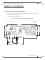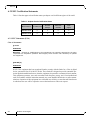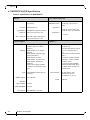
1
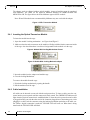
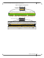
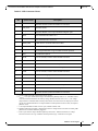
ConnectX®-2 VPI Dual Port QSFP and SFP+
Card User’s Manual
P/N: MHZH29-XTR, MHZH29-XSR
Rev 1.0
www.mellanox.com
Rev 1.0
NOTE:
THIS HARDWARE, SOFTWARE OR TEST SUITE PRODUCT (“PRODUCT(S)”) AND ITS RELATED DOCUMENTATION ARE PROVIDED BY MELLANOX TECHNOLOGIES “AS-IS” WITH ALL FAULTS OF ANY KIND AND
SOLELY FOR THE PURPOSE OF AIDING THE CUSTOMER IN TESTING APPLICATIONS THAT USE THE PRODUCTS IN DESIGNATED SOLUTIONS. THE CUSTOMER'S MANUFACTURING TEST ENVIRONMENT HAS NOT
MET THE STANDARDS SET BY MELLANOX TECHNOLOGIES TO FULLY QUALIFY THE PRODUCTO(S) AND/OR
THE SYSTEM USING IT. THEREFORE, MELLANOX TECHNOLOGIES CANNOT AND DOES NOT GUARANTEE
OR WARRANT THAT THE PRODUCTS WILL OPERATE WITH THE HIGHEST QUALITY. ANY EXPRESS OR
IMPLIED WARRANTIES, INCLUDING, BUT NOT LIMITED TO, THE IMPLIED WARRANTIES OF MERCHANTABILITY, FITNESS FOR A PARTICULAR PURPOSE AND NONINFRINGEMENT ARE DISCLAIMED. IN NO EVENT
SHALL MELLANOX BE LIABLE TO CUSTOMER OR ANY THIRD PARTIES FOR ANY DIRECT, INDIRECT, SPECIAL, EXEMPLARY, OR CONSEQUENTIAL DAMAGES OF ANY KIND (INCLUDING, BUT NOT LIMITED TO, PAYMENT FOR PROCUREMENT OF SUBSTITUTE GOODS OR SERVICES; LOSS OF USE, DATA, OR PROFITS; OR
BUSINESS INTERRUPTION) HOWEVER CAUSED AND ON ANY THEORY OF LIABILITY, WHETHER IN CONTRACT, STRICT LIABILITY, OR TORT (INCLUDING NEGLIGENCE OR OTHERWISE) ARISING IN ANY WAY
FROM THE USE OF THE PRODUCT(S) AND RELATED DOCUMENTATION EVEN IF ADVISED OF THE POSSIBILITY OF SUCH DAMAGE.
Mellanox Technologies
350 Oakmead Parkway
Sunnyvale, CA 94085
U.S.A.
www.mellanox.com
Tel: (408) 970-3400
Fax: (408) 970-3403
Mellanox Technologies, Ltd.
PO Box 586 Hermon Building
Yokneam 20692
Israel
Tel: +972-4-909-7200
Fax: +972-4-959-3245
© Copyright 2009. Mellanox Technologies, Inc. All Rights Reserved.
Mellanox®, ConnectX®, InfiniBlast®, InfiniBridge®, InfiniHost®, InfiniRISC®, InfiniScale®, and InfiniPCI® are registered
trademarks of Mellanox Technologies, Ltd.
BridgeX and Virtual Protocol Interconnect are trademarks of Mellanox Technologies, Ltd.
All other marks and names mentioned herein may be trademarks of their respective companies.
ConnectX-2 VPI InfiniBand and Ethernet Adapter Card User’s Manual
Document Number: 3157
2
Mellanox Technologies
ConnectX-2 VPI InfiniBand and Ethernet Adapter Card User’s Manual
Rev 1.0
Table of Contents
Table of Contents
List of Figures
List of Tables
3
4
5
Revision History
6
7
About this Manual
7
Chapter 1
8
Chapter 2
Overview
1.1 Adapter Cards
1.2 Mellanox Part Numbering Legend
1.3 Finding the GUID/MAC and Serial Number on the Adapter Cards
8
9
10
VPI Adapter Card Installation
12
2.1
2.2
2.3
2.4
2.5
12
12
12
13
16
Hardware and Software Requirements
Installation Instructions
Safety Warnings
Cables and Modules
Cable Lengths
Chapter 3 Driver Software and Firmware
17
3.1 Driver Software
3.2 Updating Adapter Card Firmware
3.3 Single Adapter Card Firmware Update
17
17
17
Chapter 4 Adapter Card Interfaces
4.1
4.2
4.3
4.4
18
I/O Interfaces
Power
Memory
VPD Layout for these Adapter Cards
18
20
20
21
Chapter 5 Replacing a Tall Bracket With a Short Bracket
23
5.1 Remove the Existing Bracket from the Adapter Card
5.2 Installing the New Bracket
23
23
Appendix A Specifications
25
A.1 Board Mechanical Drawing and Dimensions
A.2 EMC Certification Statements
A.3 MHZH29-X[ST]R Specifications
25
26
28
Appendix B Interface Connectors Pinout
29
B.1 I2C-Compatible Connector Pinout
B.2 PCI Express x8 Connector Pinout
B.3 QSFP Connector Pinout
B.4 SFP+ Connector Pinout
29
29
30
32
Appendix C Avertissements de sécurité d’installation (Warnings in French)
34
Appendix D Sicherheitshinweise (Warnings in German)
36
Mellanox Technologies
3
Rev 1.0
List of Figures
Figure 1:
Component Side
9
Figure 2:
Card Product Label
11
Figure 3:
SFP+ Transceiver Module
14
Figure 4:
Module With Locking Mechanism Closed
14
Figure 5:
Module With Locking Mechanism Open
14
Figure 6:
Connector Orientation
15
Figure 7:
Port Numbering
18
Figure 8:
Physical and Logical Link Indications
19
Figure 9:
I2C Connector
20
Figure 10: Flash Jumper
20
Figure 11: Adapter Card
23
Figure 12: Placing the Bracket on the Card
24
Figure 13: Schematic of the ConnectX-2 MHZH Adapter Card
25
Figure 14: Compatible Connector Plug and Pinout
29
Figure 15: Connector and Cage Views
31
Figure 16: Rear View of Module With Pin Placement
32
4
Mellanox Technologies
ConnectX-2 VPI InfiniBand and Ethernet Adapter Card User’s Manual
Rev 1.0
List of Tables
Table 1:
Revision History Table
6
Table 2:
Documents List
7
Table 3:
Mellanox Cards Part Numbering Key
9
Table 4:
Hardware and Software Requirements
12
Table 5:
Jumper Configuration
20
Table 6:
Specifications for MHZH29-XTR
28
Table 7:
I2C-compatible Connector Pinout
29
Table 8:
SFP+ Connector Pinout
33
Mellanox Technologies
5
Rev 1.0
Revision History
This document was printed on 11/3/09.
Table 1 - Revision History Table
6
Date
Rev
October
2009
1.0
Mellanox Technologies
Comments/Changes
Initial Release
ConnectX-2 VPI InfiniBand and Ethernet Adapter Card User’s Manual
Rev 1.0
About this Manual
This User’s Manual describes Mellanox Technologies ConnectX®-2 VPI IB and Ethernet PCI
Express x8 adapter cards. It provides details as to the interfaces of the board, specifications,
required software and firmware for operating the board, and relevant documentation.
Intended Audience
This manual is intended for the installer and user of these cards.
The manual assumes basic familiarity with InfiniBand® and Ethernet networks and architecture
specifications.
Related Documentation
Table 2 - Documents List
Mellanox Firmware Tools (MFT) User’s
Manual
Document no. 2204UG
User’s Manual describing the set of MFT firmware management
tools for a single InfiniBand node.
See http://www.mellanox.com > Downloads > Firmware Tools
IBTA Specification Release 1.2.1
InfiniBand Architecture Specification
IEEE Std 802.3 Specification
This is the IEEE Ethernet specification
http://standards.ieee.org/getieee802
PCI Express 2.0 Specifications
Industry Standard PCI Express 2.0 Card Electromechanical Specification, Rev 1.3.
Online Resources
• Mellanox Technologies Web pages: http://www.mellanox.com
• Mellanox Technologies Firmware download Web page:
http://www.mellanox.com => Downloads => Firmware
Document Conventions
When discussing memory sizes, MB and MBytes are used in this document to mean size in mega
bytes. The use of Mb or Mbits (small b) indicates size in mega bits.
Mellanox Technologies
7
Rev 1.0
1
Overview
Overview
This document is a User’s Manual for Mellanox Technologies network VPI adapter cards based on
the MT25408 ConnectX®-2 VPI integrated circuit device. The cards described in this manual have
the following main features:
• IBTA v1.2.1 compliant
• IEEE Std 802.3 compliant
• QSFP port for connecting InfiniBand traffic at 10Gb/s (SDR), 20Gb/s (DDR), or 40Gb/s (QDR)
• SFP+ port for connecting Ethernet traffic at 10 Gb/s
• Compliant with QSFP MSA spec Rev. 1.0
• Compatible with copper cables and optical cables with the use of QSFP and SFP+ connectors
• PCI Express 2.0 (1.1 compatible) through an x8 edge connector up to 5GT/s
• ‘Media detect circuit’ with powered connector support for the use of active cables and external
PHY fiber solutions
• EU Restriction of Hazardous Substances (RoHS) compliant
• 10 Gb/s Ethernet
1.1
Adapter Cards
The MHZH29 card is a VPI adapter card with a 40Gb/s InfiniBand QSFP connector and a 10GigE
SFP+ connector.
The QSFP connector is compatible with:
• Gigabit Ethernet
• InfiniBand Architecture Specifications
• Fibre Channel
The SFP+ connector is compatible with 10GigE.
Table 3 lists the VPI adapter cards described in this manual.
Table 3 - Adapter Cards List
8
Ordering Part
Number (OPN)
IB QSFP
Port Speed
ETH SFP+
Port Speed
Short /
Tall
Bracket
RoHS
Adapter IC
Part Number
MHZH29-XTR
40Gb/s (QDR)
10Gb/s
Tall
RoHS-R6
MT25408B0-FCCR-QI
MHZH29-XSR
40Gb/s (QDR)
10Gb/s
Short
RoHS-R6
MT25408B0-FCCR-QI
Mellanox Technologies
ConnectX-2 VPI InfiniBand and Ethernet Adapter Card User’s Manual
Rev 1.0
Figure 1: Component Side
1.2
Mellanox Part Numbering Legend
Table 4 describes the Mellanox Technologies adapter cards part numbering legend.
Table 4 - Mellanox Cards Part Numbering Key
Adapter Card
OPN
MHTS#I-XBR
Field
Decoder
M
Mellanox
Technologies
H
Adapter
Type
H = InfiniBand Host Channel Adapter, N = Ethernet Network Interface Card,
T
Media
E = CX4 SDR, G = CX4 DDR, J = CX4 QDR,
Q = QSFP QDR, R = QSFP DDR, T = UTP,
Z = one SFP+ connector and one QSFP connector
S
Silicon
H = ConnectX®, S = InfiniHost III Lx®, T= InfiniHost®,A = InfiniHost III Ex,
S = InfiniHost III Lx, T = InfiniHost
#
# ports
1 = 1, 2 = 2,
Mellanox Technologies
9
Rev 1.0
Overview
Table 4 - Mellanox Cards Part Numbering Key
Adapter Card
OPN
MHTS#I-XBR
Field
Decoder
I
Host Interface
X = PCI-X, 4 = PCIe x4, 8 = PCIe x8, 9 = PCIe (SerDes @ 5.0 GT/s)
G
Generation
<blank> = Initial product generation
-
Separator
X
Memory
Size
X = MemFree, 1=128MB, 2=256MB, 3=512MB
B
Bracket
S = Short, T = Tall, N = None
R
RoHS
<blank> = non RoHS, C = RoHS R-5 w/ Exemption, R = RoHS R-6 Lead-Free
For example, the part number MHZH29-XTR describes Mellanox Technologies’ ConnectX-2 card
with dual ports one SFP+ and one QSFP, a PCIe2.0 x8 5.0GT/s interface, no on-board memory
(mem-free), a short PCI bracket, and RoHS R5 compliance. Using the legend,
• field M = M to indicate a Mellanox Technologies product,
• field H = H to indicate an InfiniBand Adapter Card,
• field T = Z to indicate QSFP (IB QDR) and SFP+ (10GigE),
• field S = H to indicate the ConnectX family,
• field # = 2 to indicate two ports,
• field I = 9 to indicate PCI Express 2.0 x8 running at 5.0GT/s,
• field X = X to indicate no on-board memory,
• field B = T to indicate a tall bracket, and
• field R = R to indicate RoHS R6 (lead free) compliance
1.3
Finding the GUID/MAC and Serial Number on the Adapter Cards
All Mellanox adapter cards have a label on the printed side of the adapter card that has the card
serial number, the card MAC for Ethernet protocol and the card GUID for InfiniBand protocol.
VPI Cards have both a MAC and a GUID.
10
Mellanox Technologies
ConnectX-2 VPI InfiniBand and Ethernet Adapter Card User’s Manual
Rev 1.0
Figure 2: Card Product Label
S/N:MT0744X00012
REV: X1
P/N:MHZH29-XTR
GUID: 0002C9030005646 C
M AC: 0002C901122642 FC
Made in IL
Mellanox Technologies
11
Rev 1.0
VPI Adapter Card Installation
2
VPI Adapter Card Installation
2.1
Hardware and Software Requirements
Before installing the adapter card, please make sure that the system meets the hardware and software requirements listed in Table 5, “Hardware and Software Requirements”. Refer to Chapter
3,“Driver Software and Firmware” on page 17 for download and installation instructions.
Table 5 - Hardware and Software Requirements
Requirement
Hardware
Description
PCI Express x8 or x16 slots
Software
Operating
Systems/Distributions
•
For Windows
• IB see http://www.mellanox.com => Downloads => InfiniBand
SW/ Windows Drivers
• Ethernet see http://www.mellanox.com => Downloads => Ethernet
SW/ Windows Drivers
•
2.2
For Linux, both the InfiniBand and Ethernet drivers are in the Mellanox OpenFabrics Enterprise Distribution (OFED) software package available via the Mellanox
OpenFabrics Web site
http://www.mellanox.com => Downloads => InfiniBand/VPI SW/ Linux Drivers
Installation Instructions
Read all installation instructions before connecting the equipment to the power source.
2.2.1 Installation Instructions as per Host Machine
The adapter cards listed in Table 3 on page 8 are standard PCI Express cards, each with a standard
x8 edge connector. Please consult the host machine documentation for instructions on how to
install a PCI Express card.
2.3
Safety Warnings
1. Installation Instructions
Read all installation instructions before connecting the equipment to the power
source.
2. Over-temperature
This equipment should not be operated in an area with an ambient temperature
exceeding the maximum recommended: 55°C (131°F).
To guarantee proper air flow, allow at least 8cm (3 inches) of clearance around
the ventilation openings.
12
Mellanox Technologies
ConnectX-2 VPI InfiniBand and Ethernet Adapter Card User’s Manual
Rev 1.0
3. During Lightning - Electrical Hazard
During periods of lightning activity, do not work on the equipment or connect
or disconnect cables.
4. Copper InfiniBand Cable Connecting/Disconnecting
Copper InfiniBand cables are heavy and not flexible, as such they should be
carefully attached to or detached from the connectors. Refer to the cable manufacturer for special warnings and instructions.
5. Equipment Installation
This equipment should be installed, replaced, or serviced only by trained and
qualified personnel.
6. Equipment Disposal
Disposal of this equipment should be in accordance to all national laws and
regulations.
7. Local and National Electrical Codes
This equipment should be installed in compliance with local and national electrical codes.
8. Exposure to Radiation
Caution – Use of controls or adjustment or performance of procedures other
than those specified herein may result in hazardous radiation exposure.
CLASS 1 LASER PRODUCT and reference to the most recent laser standards
IEC 60 825-1:1993 + A1:1997 + A2:2001 and EN 60825-1:1994+A1:1996+
A2:2001
2.4
Cables and Modules
This card can be connected using direct copper cables or optical cables using an SFP+ transceiver
module. Copper cables can be both active and passive.
Mellanox Technologies
13
Rev 1.0
VPI Adapter Card Installation
The adapter cards are shipped without optical modules. Approved modules must be purchased
from Mellanox. The OPNs for the approved Mellanox modules are MFM1T02A-SR and
MFM1T02A-LR. The figure below shows the Mellanox approved SFP+ module.
Note: SR and LR modules not recommended by Mellanox may not work with the adapter.
Figure 3: SFP+ Transceiver Module
2.4.1 Inserting the Optical Transceiver Module
To insert the module into the cage:
1. Open the module’s locking mechanism – see Figure 4 and Figure 5.
2. Make sure that the male connectors on the module will align with the female connectors inside
of the cage. Also check that there is no dirt or foreign matter in the module or in the cage.
Figure 4: Module With Locking Mechanism Closed
Figure 5: Module With Locking Mechanism Open
3. Insert the module into the adapter card module cage.
4. Close the locking Mechanism.
To remove the module from the cage:
1. Unlock the locking mechanism by opening the handle.
2. Pull the module out of the cage.
2.4.2 Cable Installation
All cables can be inserted or removed with the unit powered on. To insert a cable, press the connector into the port receptacle until the connector is firmly seated. The GREEN LED indicator will
light when the physical connection is established (that is, when the unit is powered on and a cable
is plugged into the port with the other end of the connector plugged into a functioning port). After
plugging in a cable, lock the connector using the latching mechanism particular to the cable vendor. When a logical connection is made the YELLOW LED will come on. When data is being
transferred the YELLOW LED will blink.
14
Mellanox Technologies
ConnectX-2 VPI InfiniBand and Ethernet Adapter Card User’s Manual
Rev 1.0
Note: When installing cables make sure that the latches engage.
Note: Always install and remove cables by pushing or pulling the cable and connector in a
straight line with the card.
To remove a cable, disengage the locks and slowly pull the connector away from the port receptacle. Both LED indicators will turn off when the cable is unseated.
Cables, especially long copper cables, can weigh a substantial amount. Make
sure that the weight of the cable is supported on its own and is not hanging
from the adapter card.
2.4.2.1 Inserting a Cable into the Adapter Card
1. Support the weight of the cable before connecting the cable to the adapter card. Do this by using
a cable holder or tying the cable to the rack.
2. Determine the correct orientation of the connector to the card before inserting the connector. Do
not try and insert the connector up side down. This may damage the adapter card.
3. Insert the connector into the adapter card. Be careful to insert the connector straight into the
cage. Do not apply any torque, up or down, to the connector cage in the adapter.
4. Make sure that the connector locks in place.
Figure 6: Connector Orientation
Tie the
Cable to the
Rack
180o
2.4.2.2 Removing a Cable from the Adapter Card
1. Pull on the latch release mechanism thereby unlatching the connector and pull the connector out
of the cage.
2. Do not apply torque to the connector when removing it from the adapter card.
Mellanox Technologies
15
Rev 1.0
VPI Adapter Card Installation
3. Remove any cable supports that were used to support the cable’s weight.
2.5
Cable Lengths
Mellanox Cards support up to 40 Gb/s IB and Ethernet over the QSFP port, and up to 10Gb/s on
the SFP+ connector.
2.5.1 InfiniBand Connectivity
These Mellanox Cards support QSFP passive copper connectivity up to 7 meters, and active cable
support up to 50 meters.
2.5.2 Ethernet Connectivity
These Mellanox Cards support ethernet connectivity as defined in IEEE Std 802.3. ae standard.
The described adapter cards can be connected to switches and routers using cable lengths as specified in the tables below.
Table 6 - Max SR Cable Lengths
Cable
Max Length of Approved Cable
OM-2
82m
OM-3
330m
Table 7 - Max LR Cable Lengths
Cable
Max Length of Approved Cable
SMF
10 Km
These cards are able to support direct attached copper cables. Check www.mellanox.com => Products => Cables for cable recommendations regarding direct attached copper cables.
16
Mellanox Technologies
ConnectX-2 VPI InfiniBand and Ethernet Adapter Card User’s Manual
3
Driver Software and Firmware
3.1
Driver Software
Rev 1.0
For Linux, download and install the latest OpenFabrics Enterprise Distribution (OFED) software
package available via the Mellanox OpenFabrics Web site at:
http://www.mellanox.com => Downloads => InfiniBand/VPI SW/Drivers. Follow the installation
instructions included in the download package.
3.2
Updating Adapter Card Firmware
Each card is shipped with the latest version of qualified firmware at the time of manufacturing.
Firmware is updated occasionally, and the most recent firmware can be obtained from
http://www.mellanox.com => Downloads => Firmware.
3.3
Single Adapter Card Firmware Update
Firmware can be updated on the stand alone single card using the flint tool of the Mellanox Firmware Tools (MFT) package. This package is available for download, along with its user’s manual,
from the Mellanox Firmware Tools page. See http://www.mellanox.com => Downloads => Firmware Tools.
A firmware binaries table lists a binary file per adapter card. The file name of each such binary is
composed by combining the firmware name, the firmware release version, and the card part number. Please contact Mellanox or your assigned Field Application Engineer if you cannot find the
firmware binary for your adapter card. This may happen if the product is not yet available for general distribution.
Mellanox Technologies
17
Rev 1.0
Adapter Card Interfaces
4
Adapter Card Interfaces
4.1
I/O Interfaces
Each adapter card includes the following interfaces:
• QSFP Optical Connector
• SFP+ Ethernet Connector
• PCI Express x8 edge connector
• I/O panel LEDs
• I2C compatible connector (for debug)
Port 1 connects to the IB port of the device, while port 2 connects to the Ethernet port of the
device. See Figure 7,“Port Numbering”
Figure 7: Port Numbering
Port 1
IB port
Port 2
Ethernet
4.1.1 InfiniBand Interface
The ConnectX-2 VPI device (MT25408B0) is compliant with the InfiniBand Architecture Specification, Release 1.2.1. It has a compliant 4X InfiniBand port, with four Tx/Rx pairs of SerDes.
Each of the VPI adapter cards (listed in Table 3 on page 8) based on this device provides access to
its port by means of a QSFP connector.
This port utilizes a ‘media detect circuit’ that supports active copper cables and fiber solutions to
be connected to the InfiniBand port connectors.
4.1.2 Ethernet SFP+ Interface
The ConnectX®-2 device is compliant with the IEEE Std 802.3ae 10 Gigabit Ethernet and the
IEEE Std 802.3aq 10GBASE LRM. The SFP+ port has one Tx/Rx pair of SerDes. Each of the cards
(listed in Table 3 on page 8) based on this device provides access to their Ethernet port by means
of copper or optical cables.
18
Mellanox Technologies
ConnectX-2 VPI InfiniBand and Ethernet Adapter Card User’s Manual
Rev 1.0
4.1.3 PCI Express Interface
The ConnectX-2 adapter cards support PCI Express 2.0 (1.1 compatible) through an x8 edge connector.
4.1.4 LED Assignment
The board has I/O LEDs located on the I/O panel. The green LED, when lit, indicates that the
driver is running and a valid physical connection between nodes exists. If the green LED is blinking, it indicates a problem with the physical link. The yellow LED when lit, indicates a valid data
activity link, this is the logical link. The yellow LED illuminates when the network is discovered
over the physical link. A valid data activity link without data transfer is designated by a constant
yellow LED indication. A valid data activity link with data transfer is designated by a blinking yellow LED indication. If the LEDs are not active, either the physical link or the logical link (or both)
connections have not been established.
Figure 8: Physical and Logical Link Indications
Table 8 - LEDs
Port Number
LED Name
Port 1
Physical Link - Green
Constant on indicates a good physical link
Blinking indicates a problem with the
Physical link
Port 1
Data Activity - Yellow
Blinking indicates Data Transfer
Constant on indicates no Data Transfer
Port 2
Physical Link - Green
Constant on indicates a good physical link
Blinking indicates a problem with the
Physical link
Port 2
Data Activity - Yellow
Blinking indicates Data Transfer
Constant on indicates no Data Transfer
Note: The short bracket has the same port and LED footprint as the tall bracket.
4.1.5 I2C Compatible Interface
A three-pin header on the adapter card is provided as the I2C compatible interface. See
Figure 13,“Schematic of the ConnectX-2 MHZH Adapter Card” for the location on the board.
Mellanox Technologies
19
Rev 1.0
Adapter Card Interfaces
Figure 9: I2C Connector
4.2
Power
All adapter cards receive 12V and 3.3V power from the PCI Express Edge connector. All other
required power voltages are generated by on-board switch mode regulators. See “Specifications”
on page 25.
4.3
Memory
The adapter cards support multiple memory devices through the PCI Flash, and I2C-compatible
interfaces. The adapter card utilizes the PCI Express interface to store and access IB fabric and/or
EN fabric connection information and packet data on the system memory.
4.3.1 Flash
Each of the adapter cards include one 16MB SPI Flash device M25P16-VME6G device by ST
Microelectronics) accessible via the Flash interface of the MT25408B0 ConnectX-2 VPI device.
There is a jumper on each adapter card that indicates to the device whether an on-board Flash
device is to be used. Table 9 provides information on this jumper. See Figure 13,“Schematic of the
ConnectX-2 MHZH Adapter Card” for the jumper location.
Table 9 - Jumper Configuration
Description
Flash present/
not present
Option
connection open – Flash present
connection shorted – Flash not present
Card Default
Configuration
connection
open – Flash
present
Comments
Header 1x2
Figure 10: Flash Jumper
4.3.2 EEPROM
Each board incorporates an EEPROM that is accessible through the I2C-compatible interface. The
EEPROM is used for storing the Vital Product Data (VPD). The VPD format adheres to the PCI
Local Bus Specification Rev 2.3 VPD definition. The EEPROM capacity is 4Kb.
20
Mellanox Technologies
ConnectX-2 VPI InfiniBand and Ethernet Adapter Card User’s Manual
4.4
Rev 1.0
VPD Layout for these Adapter Cards
The PCI VPD (Vital Product Data) layout, for each of the described Mellanox Technologies ConnectX-2 VPI adapter cards comply with the format defined in the PCI 2.3 Specification, Appendix
I. All ConnectX-2 adapter cards have the same PCI VPD layout.
4.4.1
PCI VPD Layout
Table 10 - VPD Layout for MHZH29-X[ST]R
Offset (Decimal)
Item
Value
Format
Description
0
Large Resource Type ID String
Tag (0x02)
0x82
1
Length [7:0] LSB
0x6
2
Length [15:8] MSB
0x0
3
Data
RAPTOR
9
Large Resource Type VPD-R
Tag (0x10)
0x90
10
Length [7:0] LSB
0x4F
11
Length [15:8] MSB
0x00
12
VPD Keyword
PN
14
Length
0x15
15
PN
PN
%STR_SPC
36
VPD Keyword
EC
STR
Engineering Change Level of
the card (rev)
38
Length
0x2
39
Revision
RV
%STR
PCB revision
41
VPD Keyword
SN
STR
Serial Number
43
Length
0x18
44
SerialNumber
%STR_SPC
“00..00XXXX..XX”
68
VPD Keyword
V0
STR
Misc Information
70
Length
0x10
71
Data
PCIe Gen2 x8
STR_SPC
87
VPD Keyword
RV
STR
89
Length
0x1
90
Data
0,89
91
Large Resource Type VPD-W
Tag (0x11)
0x91
92
Length [7:0] LSB
0xA1
93
Length [15:8] MSB
0x00
94
VPD Keyword
V1
96
Length
0x6
97
Data
N/A
STR_SPC
103
VPD Keyword
YA
STR
STR
STR
Add in Card Part Number
%CS0
STR
EFI Driver version
Asset Tag
Mellanox Technologies
21
Rev 1.0
Adapter Card Interfaces
Table 10 - VPD Layout for MHZH29-X[ST]R
Offset (Decimal)
Item
Value
105
Length
0x20
106
Data
138
22
Format
Description
N/A
STR_SPC
“N/A”
VPD Keyword
RW
STR
Remaining read/write area
140
Length
0x72
141
Data
STR_ZERO
Reserved (0x00)
255
Small Resource Type END Tag
(0x11)
Mellanox Technologies
0x78
ConnectX-2 VPI InfiniBand and Ethernet Adapter Card User’s Manual
5
Rev 1.0
Replacing a Tall Bracket With a Short Bracket
This section provides instructions on how to remove the tall bracket of a standard Mellanox Technologies adapter card and replace it with a short one.
To replace the bracket you will need the following parts:
• the new bracket of the proper height
• one new square gasket
• the 2 screws saved from the removal of the bracket
• the 2 fiber washers saved from the removal of the bracket
5.1
Remove the Existing Bracket from the Adapter Card
Figure 11: Adapter Card
Screws
Gasket
LEDs
1. Remove the two screws holding the bracket in place.
2. The bracket comes loose from the card.
Note: Be careful not to put stress on the LEDs.
3. Save the two screws and the two fiber washers.
5.2
Installing the New Bracket
1. Remove the paper to expose the adhesive on the gasket.
2. Place the extra square gasket onto the new bracket. Make sure to correctly align the gasket with
the hole in the bracket.
Mellanox Technologies
23
Rev 1.0
Replacing a Tall Bracket With a Short Bracket
Note: If the old gasket is still on the card, remove it before installing the new bracket. Make sure
that only one gasket is used.
3. Place the bracket onto the card until the screw holes line up.
Note: Do not force the bracket onto the card. You may have to gently push the LEDs using a
small screwdriver to align the LEDs with the holes in the bracket.
4. Using the screws and washers saved from the procedure above step 1. place the screws and
washers into the holes and screw them in snug.
Figure 12: Placing the Bracket on the Card
Gasket in
place on the
bracket.
5. Make sure that the LEDs are aligned onto the bracket holes.
6. Use a torque driver to apply up to 2 lbs-in torque on the screws.
24
Mellanox Technologies
ConnectX-2 VPI InfiniBand and Ethernet Adapter Card User’s Manual
Rev 1.0
Appendix A: Specifications
A.1 Board Mechanical Drawing and Dimensions
All of the cards covered in this User’s Manual have the same mechanical drawing and share the
same dimensions as depicted in Figure 13.
Note: All dimensions are in millimeters.
Figure 13: Schematic of the ConnectX-2 MHZH Adapter Card
J3 – Flash Jumper
J1 – I2C Connector
15.00
3.65
33.35
43.13
57.13
J1
U4
L7
U11
U22
L15
Q3
68.90
Q4
U1
J5
J6
J7
64.40
56.97
U2
J4
J1
U3
167.65
U16
1.90
96.30
Mellanox Technologies
25
56.12
Rev 1.0
A.2 EMC Certification Statements
Table 11 lists the approved certification status per adapter card in different regions of the world.
.
Table 11 - Adapter Cards Certification Status
HCA Card P/N FCC Class (USA)
EN Class
(Europe)
ICES Class
(Canada)
VCCI
(Japan)
MHZH29-XSR
A
A
A
A
MHZH29-XTR
A
A
A
A
A.2.1 FCC Statements (USA)
Class A Statements:
§ 15.21
Statement
Warning! Changes or modifications to this equipment not expressly approved by the party
responsible for compliance (Mellanox Technologies) could void the user's authority to operate
the equipment.
§15.105(a)
Statement
NOTE: This equipment has been tested and found to comply with the limits for a Class A digital
device, pursuant to Part 15 of the FCC Rules. These limits are designed to provide reasonable protection against harmful interference when the equipment is operated in a commercial environment.
This equipment generates, uses, and can radiate radio frequency energy and, if not installed and
used in accordance with the instruction manual, may cause harmful interference to radio communications. Operation of this equipment in a residential area is likely to cause harmful interference
in which case the user will be required to correct the interference at his own expense.
26
Mellanox Technologies
ConnectX-2 VPI InfiniBand and Ethernet Adapter Card User’s Manual
Rev 1.0
A.2.2 EN Statements (Europe)
EN55022 Class A Statement:
Warning
This is a class A product. In a domestic environment this product
may cause radio interference in which case the user may be
required to take adequate measures.
A.2.3 ICES Statements (Canada)
Class A Statement:
“This Class A digital apparatus complies with Canadian ICES-003.
Cet appareil numérique de la classe A est conforme à la norme NMB-003 du Canada.”
A.2.4 VCCI Statements (Japan)
Class A Statement:
(Translation - "This is a Class A product based on the standard of the Voluntary Control Council for Interference by Information Technology Equipment (VCCI). If this equipment is used in a domestic environment,
radio interference may occur, in which case the user may be required to take corrective actions.")
Mellanox Technologies
27
Rev 1.0
A.3 MHZH29-X[ST]R Specifications
Table 12 - Specifications for MHZH29-XTR
Physical
Power and Environmental
Size:
Air Flow:
QSFP40Gb/s
Connector:
2.71in. x6.60in. (68.90mm x
167.65mm)
200LFM @55°C
InfiniBand (Copper and optical)
Max power per port 2.0 W.
Voltage:
Maximum Power:
12V, 3.3V
16.5W plus 3.5W for active
cables
Typ Power:
12.0W for passive cables only
15.5W for active optic modules
Temperature:
0°C to 55°C
SFP+ Connector
Ethernet (Copper and optical)
Max power per port 1.5W
Protocol Support
InfiniBand:
Ethernet:
QoS:
RDMA Support:
Regulatory
IBTA v1.2.1, Auto-Negotiation
(20Gb/s, 5Gb/s) or (10Gb/s,
2.5Gb/s)
IEEE Std 802.3ae 10 Gigabit
Ethernet
IEEE Std 802.3ad Link Aggregation and Failover
IEEE Std 802.3x Pause
IEEE Std 802.1Q VLAN tags
IEEE Std 802.1p Priorities
Multicast
Jumbo frame support (10KB)
128 MAC/VLAN addresses per
port
8 InfiniBand Virtual Lanes for
each port
EMC:
Environmental:
RoHS:
28
IEC/EN 60950-1:2001
ETSI EN 300 019-2-2
IEC 60068-2- 64, 29, 32
Yes, All Ports
Data Rate
SFP+ Ethernet:
10 Gb/s
QSFP InfiniBand:
40 Gb/s
PCI Express:
FCC 47 CFR part 15:2006, subpart B, class A
ICES-003:2004 Issue 4, class A
VCCI V-3/2007.04, class A
EN
55022:1998+A1:2000+A2:2003
class A,
EN 61000-3-2:2000+A2:2005,
EN61000-3-3:1995+A2:2005,
EN 55024:1998 +
A1:2001+A2:2003 standards,
harmonized under EMC Directive 2004/108/EC Article 6(2);
AS/NZS 3548
2.0 SERDES @ 5.0 GT/s
Mellanox Technologies
RoHS-R6
ConnectX-2 VPI InfiniBand and Ethernet Adapter Card User’s Manual
Rev 1.0
Appendix B: Interface Connectors Pinout
B.1 I2C-Compatible Connector Pinout
Figure 7: Compatible Connector Plug and Pinout
4
3
2
1
5
5 1 2 3 4
Table 13 - I2C-compatible Connector Pinout
Connector Pin Number
Signal Name
1
SPSDA
2
SPSCL
3
GND
4
NC
5
NC
B.2 PCI Express x8 Connector Pinout
The adapter cards use a standard PCI Express x8 edge connector and the PCI Express x8 standard
pinout according to the PCI Express 2.0 specification.
Mellanox Technologies
29
Rev 1.0
B.3 QSFP Connector Pinout
Table 14 - Connector Pin Name and Number to Signal Name Correspondence
Connector Pin Number
Connector Pin Name
IB Port A Signal Name
1
GND
GND
2
TXN_2
Tx2n
3
TXP_2
Tx2p
4
GND
GND
5
TXN_4
Tx4n
6
TXP_4
Tx4p
7
GND
GND
8
ModSelL_Port0
ModSelL
9
ResetL_Port0
ResetL
10
30
Mellanox Technologies
VccRx
11
SCL
SCL
12
SDA
SDA
13
GND
GND
14
RXP_3
Rx3p
15
RXN_3
Rx3n
16
GND
GND
17
RXP_1
Rx1p
18
RXN_1
Rx1n
19
GND
GND
20
GND
GND
21
RXN_2
Rx2n
22
RXP_2
Rx2p
23
GND
GND
24
RXN_4
Rx4n
25
RXP_4
Rx4p
26
GND
GND
27
ModPrsl_Port0
Mod PrsL
28
IntL
IntL
29
VccTx
30
Vcc1
31
LPMode_Port0
LPMode
32
GND
GND
33
TXP_3
Tx3p
34
TXN_3
Tx3n
35
GND
GND
36
TXP_1
Tx1p
37
TXN_1
Tx1n
38
GND
GND
SDA
GND
RX3p
RX3n
GND
SCL
RX1n
ResetL
RX1p
15
GND
14
VccRx
13
19
12
ModSelL
20 GND
21 RX2n
22 RX2p
23 GND
24 RX4n
25 RX4p
26 GND
27 ModPrsL
28 IntL
29 VccTx
30 Vcc1
31 LPMode
32 GND
14
13
12
11
1
0
9
8
7
6
5
4
3
2
1
GND
11
1
0
9
18
8
17
7
GND
15
TX2n
33 TX3p
TX2p
6
16
5
TX4p
16
GND
34 TX3n
TX4n
4
TX4n
TX4p
19
18
17
GND
35 GND
ModSelL
3
GND
ResetL
36 TX1p
SCL
2
TX2p
SDA
1
TX2n
GND
37 TX1n
GND 3 8
TX1n 3 7
TX1p 3 6
GND 3 5
TX3n 3 4
TX3p 3 3
GND 3 2
RX3p
Top 18.35
LPMode 3 1
Vcc1 30
RX3n
VccRx
GND
RX1p
RX1n
38 GND
Top
VccTx 29
IntL 28
ModPrsL 27
GND 26
RX4p 25
RX4n 24
GND 23
RX2p 22
RX2n 21
GND 20
GND
GND
18.35
8.50
View into Rear
of Module
Rev 1.0
ConnectX-2 VPI InfiniBand and Ethernet Adapter Card User’s Manual
Figure 14: Connector and Cage Views
View into Front of Cage
8.50
31
Mellanox Technologies
Rev 1.0
B.4 SFP+ Connector Pinout
Figure 15: Rear View of Module With Pin Placement
Top
13.70
8.50
VeeR
RD-
RD+
VeeR
VccR
VccT
11
12
13
14
15
16
18
19
20
VeeT 17
TD+
TD-
VeeT
7
MOD_ABS
RS0
VeeR
6
SCL
10
5
SDA
RS1
4
TX_Disable
9
3
TX_Fault
RX_LOS
2
VeeT
8
1
32
Mellanox Technologies
VeeT
2
1
TX_Fault
VeeT
20
TD3
TX_Disable
19
4
SDA
18
TD+
VeeT
5
SCL
17
6
MOD_ABS
16
7
RS0
15
VccT
VccR
VeeR
RX_LOS
8
14
RD+
13
9
RS1
12
10
VeeR
11
RD-
VeeR
SFP+ Cage
ConnectX-2 VPI InfiniBand and Ethernet Adapter Card User’s Manual
Rev 1.0
Table 15 - SFP+ Connector Pinout
Pin
Symbol Name
Description
1
VeeT
Transmitter Ground (Common with Receiver Ground) a
2
TX_Fault
Transmitter Fault.b
3
TX_Disable
Transmitter Disable. Laser output disabled on high or open. c
4
SDA
2-wire Serial Interface Data Line d
5
SCL
2-wire Serial Interface Clock Line d
6
MOD_ABS
Module Absent. Grounded within the module d
7
RS0
No connection required
8
RX_LOS
Loss of Signal indication. Logic 0 indicates normal operation. e
9
RS1
No connection required
10
VeeR
Receiver Ground (Common with Transmitter Ground) a
11
VeeR
Receiver Ground (Common with Transmitter Ground)a
12
RD-
Receiver Inverted DATA out. AC Coupled
13
RD+
Receiver Non-inverted DATA out. AC Coupled
14
VeeR
Receiver Ground (Common with Transmitter Ground) a
15
VccR
Receiver Power Supply
16
VccT
Transmitter Power Supply
17
VeeT
Transmitter Ground (Common with Receiver Ground) a
18
TD+
Transmitter Non-Inverted DATA in. AC Coupled.
19
TD-
Transmitter Inverted DATA in. AC Coupled.
20
VeeT
Transmitter Ground (Common with Receiver Ground)a
a. Circuit ground is internally isolated from chassis ground.
b. TFAULT is an open collector/drain output, which should be pulled up with a 4.7k – 10k Ohms resistor
on the host board if intended for use. Pull up voltage should be between 2.0V to Vcc + 0.3V. A high
output indicates a transmitter fault caused by either the TX bias current or the TX output power exceeding the preset alarm thresholds. A low output indicates normal operation. In the low state, the output is
pulled to <0.8V.
c. Laser output disabled on TDIS >2.0V or open, enabled on TDIS <0.8V
d. Should be pulled up with 4.7kΩ – 10kΩ on host board to a voltage between 2.0V and 3.6V. MOD_ABS
pulls line low to indicate module is plugged in.
e. LOS is open collector output. Should be pulled up with 4.7kΩ – 10kΩ on host board to a voltage
between 2.0V and 3.6V. Logic 0 indicates normal operation; logic 1 indicates loss of signal.
Mellanox Technologies
33
Rev 1.0
Appendix C: Avertissements de sécurité d’installation (Warnings in French)
1. Instructions d’installation
Lisez toutes les instructions d’installation avant de brancher le matériel à la
source d’alimentation électrique.
2. Température excessive
Ce matériel ne doit pas fonctionner dans une zone avec une température ambiante dépassant le maximum recommandé de 55°C (131°F). Un flux d’air de
200LFM à cette température ambiante maximale est nécessaire. En outre, pour
garantir un bon écoulement de l’air, laissez au moins 8 cm (3 pouces) d’espace
libre autour des ouvertures de ventilation.
3. Orages – dangers électriques
Pendant un orage, il ne faut pas utiliser le matériel et il ne faut pas brancher ou
débrancher les câbles.
4. Branchement/débranchement des câbles InfiniBand en cuivre
Les câbles InfiniBand en cuivre sont lourds et ne sont pas flexibles, il faut donc
faire très attention en les branchant et en les débranchant des connecteurs.
Consultez le fabricant des câbles pour connaître les mises en garde et les
instructions spéciales.
5. Installation du matériel
Ce matériel ne doit être installé, remplacé ou entretenu que par du personnel
formé et qualifié.
6. Elimination du matériel
L’élimination de ce matériel doit s’effectuer dans le respect de toutes les législations et réglementations nationales en vigueur.
34
Mellanox Technologies
ConnectX-2 VPI InfiniBand and Ethernet Adapter Card User’s Manual
Rev 1.0
7. Codes électriques locaux et nationaux
Ce matériel doit être installé dans le respect des codes électriques locaux et
nationaux.
This equipment should be installed in compliance with local and national electrical codes.
8.
Exposition au rayonnement grave
Mise en garde – l'utilisation de commandes ou de réglages ou l'exécution de
procédures autres que ce qui est spécifié dans les présentes peut engendrer une
exposition au rayonnement grave.
PRODUIT LASER DE CLASSE 1 » et références aux normes laser les plus
récentes CEI 60 825-1:1993 + A1:1997 + A2:2001 et NE 608251:1994+A1:1996+ A2:2001
Mellanox Technologies
35
Rev 1.0
Appendix D: Sicherheitshinweise (Warnings in
German)
1. Installationsanleitungen
Lesen Sie alle Installationsanleitungen, bevor Sie das Gerät an die Stromversorgung anschließen.
2. Übertemperatur
Dieses Gerät sollte nicht in einem Bereich mit einer Umgebungstemperatur
über der maximal empfohlenen Temperatur von °C (°F) betrieben werden. Es
ist ein Luftstrom von 200 LFM bei maximaler Umgebungstemperatur erforderlich. Außerdem sollten mindestens 8 cm (3 in.) Freiraum um die Belüftungsöffnungen sein, um einen einwandfreien Luftstrom zu gewährleisten.
3. Bei Gewitter - Elektrische Gefahr
Arbeiten Sie während eines Gewitters und Blitzschlag nicht am Gerät,
schließen Sie keine Kabel an oder ab.
4. Anschließen/Trennen von InfiniBand-Kupferkabel
InfiniBand-Kupferkabel sind schwer und nicht flexible. Deshalb müssen sie
vorsichtig an die Anschlüsse angebracht bzw. davon getrennt werden. Lesen
Sie die speziellen Warnungen und Anleitungen des Kabelherstellers.
5.
Geräteinstallation
Diese Gerät sollte nur von geschultem und qualifiziertem Personal installiert,
ausgetauscht oder gewartet werden.
6. Geräteentsorgung
Die Entsorgung dieses Geräts sollte unter Beachtung aller nationalen Gesetze
Bestimmungen erfolgen.
36
Mellanox Technologies
ConnectX-2 VPI InfiniBand and Ethernet Adapter Card User’s Manual
Rev 1.0
7. Regionale und nationale elektrische Bestimmungen
Dieses Gerät sollte unter Beachtung der regionalen und nationalen elektrischen
Bestimmungen installiert werden.
8. Strahlenkontakt
Achtung – Nutzung von Steuerungen oder Einstellungen oder Ausführung von
Prozeduren, die hier nicht spezifiziert sind, kann zu gefährlichem Strahlenkontakt führen..
Klasse 1 Laserprodukt und Referenzen zu den aktuellsten Lasterstandards :
ICE 60 825-1:1993 + A1:1997 + A2:2001 und EN 60825-1:1994+A1:1996+
A2:2001
Mellanox Technologies
37