1
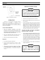
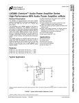
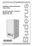
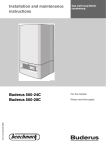
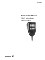
LBI-39181 Maintenance Manual DTMF Microphone 344A4611P1 & P2 ericssonz LBI-39181 TABLE OF CONTENTS INFORMATION TO USERS........................................................................................................................... GENERAL........................................................................................................................................................ FEATURES ...................................................................................................................................................... SPECIFICATIONS........................................................................................................................................... MOUNTING .................................................................................................................................................... MICROPHONE CABLES................................................................................................................................ MICROPHONE CONNECTOR WIRING ....................................................................................................... ADJUSTMENTS.............................................................................................................................................. OPERATION.................................................................................................................................................... SERVICE INSTRUCTIONS ............................................................................................................................ REPLACEMENT PARTS ................................................................................................................................ OPTIONAL ACCESSORY .............................................................................................................................. SCHEMATIC DIAGRAM ............................................................................................................................... INFORMATION TO USERS This equipment has been tested and found to comply with the limits for a Class B digital device, pursuant to Part 15 of the FCC Rules, and as set out in the Radio interference Regulations of the Canadian Department of Communications. These limits are designed to provide reasonable protection against harmful interference in a residential installation. This equipment generates, uses and can radiate radio frequency energy and, if not installed and used in accordance with the instructions, may cause harmful interference to radio communications. However, there is no guarantee that interference will not occur in a particular installation. If this equipment does cause harmful interference to radio or television reception, Page 2 3 3 4 4 5 5 5 6 6 7 8 9 which can be determined by turning the equipment off and on, the user is encouraged to try to correct the interference by one or more of the following measures: Reorient or relocate the receiving antenna. • • Increase the separation between the microphone and receiver. • Connect the microphone transmitter to an outlet on a circuit different from that to which the receiver is connected. • Consult the dealer or an experienced radio/TV technician for help. CREDITS MODULINK, ARMO-DUR, Million-Cycle Plus, and Top-Talk Sound Channels are trademarks of Shure Brothers Inc. NOTICE! This manual covers Ericsson and General Electric products manufactured and sold by Ericsson Inc. NOTICE! Repairs to this equipment should be made only by an authorized service technician or facility designated by the supplier. Any repairs, alterations or substitution of recommended parts made by the user to this equipment not approved by the manufacturer could void the user’s authority to operate the equipment in addition to the manufacturer’s warranty. NOTICE! This device complies with Part 15 of the FCC Rules. Operation is subject to the following two conditions: (1) this device may not cause harmful interference, and (2) this device must accept any interference received, including interference that may cause undesired operation This manual is published by Ericsson Inc., without any warranty. Improvements and changes to this manual necessitated by typographical errors, inaccuracies of current information, or improvements to programs and/or equipment, may be made by Ericsson Inc., at any time and without notice. Such changes will be incorporated into new editions of this manual. No part of this manual may be reproduced or transmitted in any form or by any means, electronic or mechanical, including photocopying and recording, for any purpose, without the express written permission of Ericsson Inc. Copyright September 1995, Ericsson Inc. 2 LBI-39181 GENERAL Model 344A4611 is a hand-held, amplified, condenser DTMF communications microphone with an illuminated keypad. The microphone is ideal for upgrading existing twoway radios for use with advanced telephone interconnect systems or for new installations. It is designed for rugged and reliable operation in any mobile communications application. The microphone has an omni-directional pickup pattern and provides extremely clear transmission, even in noisy environments. In addition to its clear, crisp, natural voice response, the microphone has extremely low sensitivity to hum pickup and low susceptibility to radio frequency interference. easily visible during night operation and minimizing eye readjustment for night vision. The microphone is supplied with a small screwdriver for adjusting the microphone amplifier gain and DTMF level, and for releasing the modular-plug microphone cable from the microphone. FEATURES • Top-Talk Sound Channels™ for clear voice input, easy handling • Built-in transistor amplifier (powered by carbonmicrophone- type circuit) • Frequency response from 200 to 4,000 Hz, tailored for voice communications • Illuminated keypad with positive tactile feel and audible confirmation tones • Auto push-to-talk (APTT) automatically keys transmitter when keypad is depressed The microphone is designed for use with most currently available mobile two-way radio transceivers. For installation convenience, all microphone and signalling functions, including keypad illumination, are powered directly from the microphone input circuit of most transmitters, minimizing the need for equipment modification. The microphone is compatible with a choice of five-conductor, pre-wired, coilcord MODULINK® cables, each of which has a telephonetype modular plug on the microphone end, and a choice of popular transmitter input connectors on the other. The cables are instantly changed or replaced without soldering. • Convenient external microphone gain adjustment accommodates most input circuits • Simple, easy-to-use continuous-tone dialing • Externally accessible DTMF level independent of microphone gain setting • Modular-plug coil-cord-easily attached and removed • Low susceptibility to radio frequency interference The microphone features attractive, contemporary styling, designed to blend with most radio designs and vehicle interiors. The microphone is ergonomically designed; it fits naturally and comfortably in the hand and is not affected by heat or humidity. The rugged ARMO-DUR® case is immune to oil, grease, most fumes and solvents, salt spray, sun, rust and corrosion. It is outstanding in its ability to withstand mechanical shocks and vibration. The MillionCycle PIus™ leaf-type switch is a double-pole, single-throw type, designed to resist the effects of severe operating conditions and constant usage. It has nickel-silver blades, and its contacts are palladium-alloyed for reliable, oxidation-free operation. • Low sensitivity to hum pickup • Rugged Million-Cycle Plus leaf-type switch stands up under severe environments and constant use • High-impact ARMO-DUR case - stronger and lighter than diecast metal, comfortable to the touch in hot or cold weather • Rugged and dependable under all operating conditions • Hang-up button connection available for microphone hang-up sensing (mounting bracket must be grounded) For installations where transmitter input gain requires sensitivity modification, the microphone has convenient, externally accessible screwdriver controls for independent adjustment of both microphone and DTMF levels. This eliminates the problem of fixed audio levels and the necessity for disassembling the microphone for adjustments. Restricting control access also prevents accidental changes common to external controls. adjustment, The microphone’s keypad is made of tough silicone rubber, with durable printed characters that will last the life of the microphone. The keypad is backlit by red LEDs, 3 LBI-39181 SPECIFICATIONS (Test conditions unless otherwise specified: audio output measured between pin 2 and ground; PTT switch depressed; no hang-up button connection; mic and DTMF level trimmers full clockwise; dc VTVM 10 MΩ or greater input impedance; ac VTVM 1 MΩ or greater input impedance.) Environmental Conditions Operating Temperature: -40° to 60° C (-40° to 140° F) Storage Temperature: -54° to 85° C (-65° to 185° F) Relative Humidity 0 to 95% (non-condensing) Microphone Connector 6-conductor modular telephone type PTT Switch Assembly Type Electret condenser (with transistor preamplifier, DTMF signaling circuitry, illuminated keypad) Mechanical: Double-pole, single-throw, leaf-type, normally open. Electronic: Open NPN transistor collector to ground; positive polarity only; maximum on-state current 100 mA to produce 0.6 V or less; maximum off-state voltage 40 V. Cable Detachable, 1.4 m (48 in.), 5-conductor (1 shielded), vinyl-rubber-jacketed coil cord with modular plug on microphone end Construction Figure 1 - Typical Frequency Response Frequency Response 200 to 4,000 Hz (see Figure 1) Polar Pattern Omnidirectional Output Level (at 1,000 Hz, 1 cm) -6.0 dB (V+ = 12 V) (0 dB = 1 V per 100 µbars) Case Switch Button Keypad Black textured high-impact ARMO-DUR Black ARMO-DUR Molded silicone rubber Dimensions See Figure 2 Net Weight 160 grams (5.6 oz) MOUNTING DC Supply Current 4.0 mA at 12 V Hum Sensitivity -94 dBV maximum in 1 Oe 60 Hz field (mic level control full counterclockwise) DTMF Output Level 1.0 V peak-to-peak Audio Polarity Positive sound pressure produces positive voltage at pin 6 of modular connector with respect to ground 4 The microphone is provided with a rear-case hang-up button for use with a grounded mounting bracket on or near associated equipment. Grounding of the bracket is the customer's responsibility. Heavy-duty, chrome-plated mounting brackets are available Part No. 344A4678P1. LBI-39181 Figure 2 - Overall Dimensions IMPORTANT: The microphone hang-up button is connected to the blue cable conductor for radios with microphone hang-up sensing. MICROPHONE CABLES Figure 4 - Equipment End Cable Wiring The cable is attached to the microphone by inserting the modular telephone-type plug in the microphone jack until it locks. To remove the cable from the microphone, insert the small screwdriver supplied with the microphone in rear case hole "A" just above the cable jack (see Figure 5) to unlock the plug and withdraw the plug from the jack. ADJUSTMENTS Figure 3 - Microphone End Cable Wiring MICROPHONE CONNECTOR WIRING After connection to the communications equipment and with equipment power turned on, the microphone sensitivity and DTMF output levels should be adjusted with the supplied screwdriver as follows. 1. MICROPHONE SENSITIVITY: Press the push-to-talk button and speak normally into the microphone while observing transmitter modulation. Adjust the microphone sensitivity control (rear case hole "B" in Figure 5) and repeat the talk test as required. 2. DTMF OUTPUT: Do not press the push-to-talk button. Depress and hold down the "#" key for a continuous tone. Adjust the DTMF output control (rear case hole "C" in Figure 5) for 60% of rated system deviation. Part No. P1 (Fig. 4A) P2 (Fig. 4B) Color Function Black A– 7 1 Yellow — PTT 3 10 White Mic Hi 1 4 Red Switched A+ 6 2 Drain Mic Lo 2 5 Blue — CG Dis 8 6 5 LBI-39181 SERVICE INSTRUCTIONS CAUTION These microphones contain static-sensitive semiconductor devices. All work must be performed at a static-free work station using properly grounded equipment. Soldering operations must be performed using a fine-pointed low-wattage soldering iron. Figure 5 - Microphone Case Rear OPERATION Operation of all microphone and DTMF functions requires that the microphone is connected to the communications equipment and that the equipment power is turned on. Power application can be verified by observing keypad LED backlighting. TO DISASSEMBLE THE MICROPHONE 1. Disconnect the microphone and remove the cable. 2. Remove the four Phillips-head screws from the back of the microphone. 3. Hold the microphone with its back toward you and the cable connector down. Carefully separate the case back slightly from the front. Pivot the case back to the right taking care not to damage any internal leads or components. Observe that four leads attach the leaf switch to the boards, and one blue lead attaches the rear board to the terminal in the center of the case back. VOICE TRANSMISSION 1. Hold the microphone comfortably in the hand, positioned so that the Top-Talk Sound Channels at the top of the case are near the mouth. The clearest sound is often obtained with the microphone at the corner of the mouth, with the cable away from the face. 2. Press the push-to-talk button and make sure the equipment is in the transmit mode before speaking. 3. Release the push-to-talk button before dialing. TO DETACH THE CASE BACK AND REAR PRINTED CIRCUIT BOARD 1. With the partially disassembled microphone face down on a flat surface and with the cable entry toward you, locate the multipin connector on the left side between the center board and the rear board. Carefully pry the rear board away from the connector on the center board. (To start the process, the flat blade of a small screwdriver can be inserted between the terminal pins connected to the rear board and the connector attached to the center board.) 2. Lift the microphone case back and the rear board away from the center board. DIALING 1. Do not depress the push-to-talk button. 2. Press the desired keypad buttons in sequence. A highpitched tone will confirm that the code has been transmitted. 3. When the first keypad button is pushed, the transmitter is automatically keyed. The transmitter will remain keyed for approximately 1.5 seconds after the button is released. 6 CAUTION The center semiconductor damaged by procedures are board. board contains static-sensitive devices that can be functionally handling. Make certain proper followed when working with this LBI-39181 TO SEPARATE THE CENTER BOARD FROM THE FRONT BOARD 1. Observe that a flexible ribbon cable connects the center board to the front board. To detach this cable, with the case front still face down on the table and the cable entry still toward you, carefully unsolder the tabbed leads. 2. Rotate the case front so the voice entry port is toward you. Use the two cylindrical posts at diagonal corners of the board to lift the center board away from the front board. The flat blade of a small screwdriver, inserted under the board edge near the voice entry port, may be used to aid in carefully prying the center board (which is now uppermost) away from the front board. TO REASSEMBLE THE 344A4611 Reassemble the microphone by reversing the steps of disassembly. Figure 6 shows the configuration of connectors between the front, center, and rear boards in the microphone. Back-to-back connectors on the side of the center board opposite the push-to-talk switch attach to the rear and front boards. When pried up, the center board will detach at this connector. The orange lead from the push-to-talk switch is connected to the center board. To complete separation of the center board, unsolder the orange lead at the leaf switch. 3. Lift the center pc board out of the case. TO REMOVE THE FRONT BOARD FROM THE CASE 1. Remove the two flat-head Phillips screws, one from each side of the board. 2. Remove the insulator around the base of the flexible cable. Thread the cable through the slot in the board. Lift the board free of the case, carefully sliding the whole length of the flexible cable through the slot. Figure 6 - Connector Detail Between Boards TO REPLACE THE MICROPHONE CARTRIDGE 1. Remove the flexible black resonator from the cartridge on the rear board. 2. Unsolder the three cartridge terminals from the board and detach the cartridge from the board. 3. Insert the new cartridge terminals in the board with the single (ground) terminal in the hole closest to the edge of the board and the other two terminals (with the insulator connecting them together) toward the center of the board. Insert the terminals until the posts on the front of the cartridge body stop at the board surface. To free the rear board from the case back, unsolder the leads from the hang-up button and leaf switch terminals. 4. Carefully solder the new cartridge terminals to the board. To remove the leaf switch assembly, remove the two Phillips-head screws that attach it to the case back. 5. Replace the black resonator on the cartridge with its long flat edge parallel to the rear of the board. TO CONCLUDE DISASSEMBLY OF THE MICROPHONE The membrane switch assembly and keypad can now be lifted out of the case. 1. 2. 7 LBI-39181 REPLACEMENT PARTS Cable and Modular Plug (Figure 4A) 344A4611P21 Cable and Modular Plug (Figure 4B) 344A4611 P22 OPTIONAL ACCESSORY Mounting Bracket Figure 7 - Parts Layout 344A4611 8 344A4678P1 SCHEMATIC DIAGRAM LBI-39181 (98E401-11-2) 9 Ericsson Inc. Private Radio Systems Mountain View Road Lynchburg, Virginia 24502 1-800-528-7711 (Outside USA, 804-528-7711) Printed in U.S.A.