1
OPERATOR'S
MANUAL
DieHard,°
BATTERY CHARGER
50/15/2 Amp,
6/12 Volt,
Manual
250 Amp
ENGINE STARTER
Model No.
200.71240
CAUTION:
Read and follow all Safety
Rules and Operating Instructions
Before Every Use of this Product.
SAVE THESE INSTRUCTIONS.
.....................
Sears, Roebuck and Co., Hoffman Estates, IL 60179 U.S.A.
00-99-000853/0808
SECTION
PAGE
1.
IMPORTANT SAFETY INSTRUCTIONS
1
2.
PERSONAL
2
3.
PREPARING TO CHARGE
2
4.
CHARGER LOCATION
3
5.
DC CONNECTION
3
PRECAUTIONS
PRECAUTIONS
6. WHEN BATTERY IS INSTALLED
IN VEHICLE
3
7. WHEN BATTERY IS OUTSIDE OF VEHICLE
4
8.
BATTERY CHARGING
5
9.
PARTS
- AC CONNECTIONS
7
10. PRODUCT FEATURES
8
11. ASSEMBLY
8
INSTRUCTIONS
12. OPERATING
INSTRUCTIONS
13. CALCULATING
CHARGE TIME
11
12
14. USING THE ENGINE START FEATURE
14
15, MAINTENANCE
14
16. STORAGE
INSTRUCTIONS
INSTRUCTIONS
17. TROUBLESHOOTING
14
15
DIEHARD THREE-YEAR FULL WARRANTY
When operated and maintained according to all supplied instructions,
if this DieHard product fails due to a defect in material orworkmanship within three years from the date of purchase, return it to any Sears
store or other DieHard outlet in the United States for free replacement.
This warranty gives you specific legal rights, and you may also have
other rights which vary from state to state.
SEARS, ROEBUCK AND CO., HOFFMAN ESTATES, IL 60179
FOR CUSTOMER ASSISTANCE OR REPLACEMENT PARTS, CALL
TOLL-FREE FROM 7 AM TO 4:30 PM CT MONDAY THROUGH FRIDAY:
1-800-SEARS-64 (1-800-732-7764)
IMPORTANT: READ AND SAVE THIS SAFETY AND INSTRUCTION
MANUAL.
1.1
SAVE THESE INSTRUCTIONS - The DieHard model 71240 Manual Batten.7Charger, offers a wide range of features to accommodate the needs
for home or light commercial use. This manual will show you how to use
your charger safely and effectively. Please read and follow these instructions and precautions carefully as this manual contains important safety
and operating instructions.
t.2
WARNING: This product contains chemicals known to the State of California to cause cancer and birth defects or other reproductive harm. Wash
hands after handling.
t.3
Do not expose charger to rain or snow.
1.4
. Use of an attachment not recommended or sold by the battery charger
manufacturer may result in a risk of fire, electric shock or injury to persons.
1.5
To reduce the risk of damage to electric plug or cord, pull by the plug
rather than the cord when disconnecting the charger,
1,6
An extension cord should not be used unless absolutely necessary. Use of
an improper extension cord could result in a risk of fire and electric shock.
If an extension cord must be used, make sure:
- That the pins on the plug of the extension cord are the same number,
size and shape as those of the plug on the charger.
- That the extension cord is properly wired and in good electrical condition
and;
• That the wire size is large enough for the AC ampere rating of the charger
as specified in Table 8.3.
1.7
Do not operate the charger with a damaged cord or plug; take it to a qualified serviceman. (Ca!l customer service at: 800-SEARS-64).
1.8
Do not operate the charger if it has received a s harl5 blowl been dropped
or otherwise damagedin any way; take it to a qualified serviceman. (Call
cListomer service at:800-SEARS-64).
1.9
Do not disassemble the charger; take it to a qualified serviceman when
sewice or repair is required, lncoi-rect reassembly may result in a risk of
electric shock or fire. (Call customer service at: 800-SEARS-64).
1.10
To reduce the risk of electric shock, unplug the charger from the outlet
before attempting any maintenance or cleaning. Turning off the controls
will not reduce this risk.
11
o
.
,
WARNING - RtSK OF EXPLOSIVE
GASES.
WORKING IN THE VICINITY OF A LEAD-ACID BATTERY IS DANGEROUS. BATTERIES GENERATE EXPLOSIVE GASES DURING NORMAL BATTERY OPERATION. FOR THIS REASON, IT IS OF UTMOST
IMPORTANCE THAT YOU FOLLOW THE INSTRUCTIONS EACH TIME
YOU USE THE CHARGER.
TO REDUCE THE RISK OF BATTERY EXPLOSION, FOLLOW THESE
INSTRUCTIONS AND THOSE PUBLISHED BY THE BATTERY MANUFACTURER AND THE MANUFACTURER OF ANY EQUIPMENT YOU
INTEND TO USE IN THE VICINITY OF THE BATTERY. REVIEW THE
CAUTIONARY MARKINGS ON THESE PRODUCTS AND ON THE
ENGINE,
2.t
Consider having someone close enough by to come to your aid when you
work near a lead-acid battery.
2,2
Have plenty of fresh water and soap nearby in case battery acid contacts
your skin, clothing or eyes.
2.3
Wear complete eye protection and clothing protection. Avoid touching your
eyes whiie working near the battery.
2.4
If battery acid contacts your skin or clothing, wash immediately with soap
and water. If acid enters your eye, immediately flood the eye with cotd running water for at least 10 minutes and get medical attention immediately.
2.5
NEVER smoke Or allow a spark or flame inthe vicinity of a battery or
engine.
2.6
Be extra cautious to reduce the risk of dropping a metal too] onto the battery. It might spark or short-circuit the battery or other electricat Part that
may caiJse an explosion.
2,7
Remove personal metal items such as rings,bracelets, necklaces ancl
watches when Working with a lead-acid battery. A lead:acid battery can
produce a short-circuit current high enough to weld a ring or the tike to
metal, causing a severe burn.
2.8
Use this charger for charging a LEAD-ACiD battery, on.ly, tt is not intendecl
to supply power to a low.voltage electrical system other than in a startermotor application. Do not use this battery charger for charging dry-cel!
batteries that are commonly used with home appliances. These batteries
may burst and cause injury to persons and damage to property.
2.9
NEVER charg e a frozen battery.
2.10
WARNING: Pursuant to California Proposition 65, this product contains
chemicals known to the State of California to cause cancer and birth defects or other reproductive harm.
-2.
3.1
3.2
If it is necessary to ,remove the battery from the vehicle to charge it, always remove the grounded terminal from the battery firsL Make sure all of
the accessories in the vehicle are off, so as not to cause an arc.
Be sure the area around the battery is welt ventilated while the battery is
being charged.
3.3
Clean the battery terminals. Be careful to keep corrosion from coming into
contact with your eyes.
3.4
Add distilled water to each celt t_ntil the battery acid reaches the level
specified by the battery manufacturer. Do not overfill. For a battery without
removable cell caps, such as valve regulated lead-acid batteries, carefully
follow the manufacturer's recharging instructions.
3.5
o
Study all of the battery manufacturer's
and _ecommended fates of charge.
specific precautions while charging
. •
3.6
Determine the voltage of the battery by referring to the vehicle ,owner's
manual arid make sure that the output voltage selector switch is set to the
correct voltage. If the charger has an adjustable charge rate, charge the
battery at the Iowes{ rate first,
•.
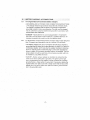
4.t
Locate the charger as far away from the battery as the DC cables permit.
4.2
: '
Never place the charger directly above the battery being charged; gases
from the battery will corrode and damage the charger.
4.3
Never allow battery acid to drip onto the charger when reading tt_e electrolyte specific gravity or filling the battery.
4.4
Do not operate the charger in a closed-in area or restrict the ventilation in
any way,
4.5
Do not Set a battery on top of the charger.
5,1
Connect and disconnect the DC output clips only after.setting alt of the.
charger switches to the "off' positionand
removing the AC plug from the
electrical outlet. Never allow the clips to touch each other.
5.2
Attach the Clips to the battery and chassis,
and 7.2 thru 7.4.
-3,
as indicated
in steps 6.5i 6.6,
A SPARK NEAR BATTERY MAY CAUSE BATTERY EXPLOSION.
REDUCE RISK OF A SPARK NEAR BATTERY:
NEGATIVE GROUNDED
TO
SYSTEM
6,1
Position the AC and DC cables to reduce the risk of damage by the hood,
door, or moving engine parts.
6.2
Stay clear of fan blades, belts, pulieys and other parts that can cause
injury.
6.3
Check the polarity ofthe battery posts. The POSITIVE (POS, P, +) battery
post usually• has a larger diameterthan the NEGATIVE (NE G, N, -) post.
6.4
Deterrnine which post of the battery is grounded (connected) to the chassis. If the negative post is grounded to the chassis (as in laost vehicles),
see step 6.5. If the positive post is greunded to the• chassis, see step 6.6.
6:5
For anegativeLgmunded
vehicle,, connect the POSITIVE (RED) clip from
tile battery charger to the POSITIVE (POS, P, +) ungrounde d post of the
.battery. Connect the NEGATIVE (BLACK).clip to the vehicle -chassis or.
engine.block away from the battery. Do not c0nne(;t the (;lip tothe carburetor,fue! lines or sheet-metal body parts-. Connect to a heavy gauge metal
part of the frame or engine block. ""
6,6
For a positive-gr0unded vehicle, connect the NEGATIVE (BLACK) dip .
from the battery charger to'the NEGATIVE(NEG, N, -:) ungrounded post
of the battery. Connect the POSITIVE (RED) clip to the vehicle chassis or
engine block away from the battery. Do not connect the clip to the carburetor, fuel lines or sheet-metal body parts. Connect to a heavy gauge metal
part of the frame or engine block.
6.7
When disconnectingthe charger, turn aIf switches to off, disconnect the
AC cord remove the clip from the vehicle chassis, and then remove the
Clip from the battery terminal.•
6.8
see OPERATING INSTRUCTIONS
,4,
for length of charge information.
ASPARKNEAR
THE BATTERY MAY CAUSE BATTERY
TO REDUCE RISK OF A SPARK NEAR BATTERY:
EXPLOSION,
7.t
• Check the polarity Of the battery posts. The POSITIVE (POS, P,+) battery
post usually has a larg'er diaineter than theNEGAT1VE (NEG, N, -) post.
7.2
Attach at least a 24-inch-long 6-gauge (AWG) insulated battery cable to
the NEGATIVE (NEG, N, -) battery post.
7.3
Connect the POSITIVE (RED) charger clip to the POSITIVE
post of the battery.
7.4
(POS, P, +)
Position yourself and the free end of the cable you previously attached to
the NEGATIVE (NEG, N, -) battery post as faraway from the battery as
possible - then connect the NEGATIVE (BLACK) charger clip to the free
end of the cable.
7.5
DO not "face the battery when making the final .connection.
7.6
When disconnecting the charger, always do so in reverse sequence of
the connecting procedure and break the first connection while as far away
from the battery as practical.
7.7
A marine (boat) battenj must be removed ai-_dcharged on shorel To
charge i{ onboard requires equipment specially designed for marine use.
-5-
8.1 Forallgrounded
cord-connected
battery
chargers:
• GROUNDING AND AC POWER CORD CONNECTION INSTRUCTIONS
- The charger should be grounded to reducethe risk of electric shock.
The charger is equipped with an electric cord having an equipmentgrounding conductor and a grounding plug. The plug must be plugged
into an outlet that is properly installed and grounded in accordance with
all local codes and ordinances.
.
• DANGER - Never alterthe AC cord or plug provided -_ if it will hot fit
the outlet, have the proper outlet installed by a qualified electrician. An
improper connection can result in a risk of an electric shock.
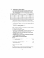
8.2
For all grounded, cord-connected battery chargers with an input rating less
than 15-amperes and intended for use on a nominal 120-volt circuit:
• This battery charger is.for use on a nominal 120-vott circuit, add has a
grounding plug that looks like the plug illustrated in sketch A in Figure 8.4..
A temporaryadai3tor, which looks like the adapter illustrated in sketchesB and C, maybe used to connect this plug to a two-pole receptacle.as
shown in sketch B if a pi'operty grounded outlet is not available. The temporary adapter should be used only until a properly grounded outlet can
be instal ed by a qualified electrician.
• DANGER - Before using an adapter as illustrated, be certain that the
center screw of the outlet plate is grounded. The green-colored rigid
ear or lug extending from the adapter rnust be connected to .a properly
grounded outlet- make certain it is grounded. If necessary, reptace the •
original outlet cover plate screw with a longer screw that wilt secure.the
adapter ear or lug to the outlet cover plate and make a ground connection to the grounded outlet•
,6,
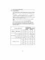
8.3 Recommended
minimum
AWGsizeforextension
cordsfo(battery
chargers:
ACinputrating,
AWGsizeofcord
.-. amperes a .......................................................
Length of cord, feet (m)
At least
But less "
25
50
100
than
(7.6)
(15.2)
(30.5)
0
2
18
t8
t8
150
(45.6)
16
.................
2................................
%.............................
18 ................
_T:..........................
116
.................................
p;............
• '34"
4
5
.... 5 ............... 6 ..........
6
8
8
10
10
12
!'8
" t8
-t6 '
14"
18
18
14
12
18...........
......: .........i4:1 ......... 12
18
16
12
10
18
14
12
10
16
14
10
8
...........
12.....................
_'4..........................
i'e''_..........
: 'i2" .................
to........................
8...................
..............
! 4 .......................
!6 ...................
1.6.............................
1:2..........................
10........................
8................
.............
!6 .......................
!8........................
t4j ...................
!2 .................
8............. 8........
t8
.
20
...
14
12
8
6
alf the input rating of a charger is given in watts rather than in
amperes, the corresponding ampere rating is to be determined
by dividing the wattage rating by the voltage rating - for
example:
i250 watts/125 volts = t0 amperes
8.4
Grounding
I
Methods
M_TA.LSCREW
CDVER
" PIN
::
-_
(A)
DE GRDUND£D
]II
II I
(B)
'.
ADAPTER
(C)"
GROUNDING
MEANS
GRBU
RIN "-----I ,
(D)
AA2i0
"7"
Volt Selector
Switch
2. Ammeter
3.
Clamps
4.
Timer
In case of charger malfunction,
DO NOT attempt to repair charger
yourself. To arrange for charger repair, or information
about customer replaceable parts, call 1-800-SEARS-65 (1-800-732-7764).
It is important to fully assemble your charger before use. Follow these
instructions for assembly:
PARTS •
TOOLS NEEDED
............................................
Two, 10_32,thread cutting screws
Four, 1/4-20, thread cutting screws
Two wheels.
One axle
Two axle caps
Two axle brackets
One handle
•.
318" wrench (for mounting foot)
5/.16"wrench (for wheels)
Hammer
Ph[ltips screwdriver
One mounting foot
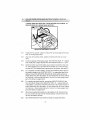
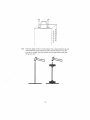
TO ATTACH THE AXLE ASSEMBLY:
t0.1
Remove charger from packing materials and place upside down on a flat
surface. Attach mounting foot and secure with the four, i/4-20 thread cutting screws•
''8"
jJ
10.2
Hold axle upright on floor or work surface: Then, using a hammer, tap one
of:the plastic axle caps.onto the top end Of the axle. Be sure to tap the
axle cap on straight• Slide both wheels (_nto the axle with the axle caps
facing each other.
tm
.9
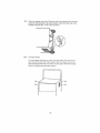
10.3
Place th e charger on its side, Place one end of each brac.ket into, slot, then
place the axle assembJy under each bracket. Fasten the other side of the
brackets using the two, 10-32 screws 3rovided.
10.4
To Attach Handle:
Turn tt_e,charger right side up onto its foot and wheels. Remove the two
top screws from each side of the charger• Align the handle so the screw
holes are aligned with the screw holes on each side of the wheel charger.
Attach the handle using the same screws.
I
• 10-
't
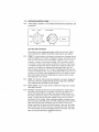
11.1
Follow steps in section 6 or 7 for hookup and disconnect instructions
precautions,
VQLTIRAT£
S ELEG_O£
CHARGE
and
_ME/NI_UTES
IZ v_
Ammeter
Slt_l
SETTING THE CONTROLS
All controls for your charger are located on the front of the unit, Follow
these instructions to obtain the accurate charge level for your ba{tery.
11.2
TIMER: The mainfunction of-the timer is to prevent over charging white all
towing the battery time to obtain a satisfactory charge. To properly set the
timer you must know the size of the battery in ampere hours or reserve
capacity in minutes, and the state of charge. Often, the state of charge
is not known, which is why the timer is limited to 2.25 hours. With the aid
of a battery load teste[, the state of charge can be obtained within a few
seconds: For example, the average size automo:tive battery at a 50%
. state of charge, w[lt require 1 to 1.5 hours ofcharging at t.he 50 amp rate
to reach the full charge state. For the same battery with the timer set to its
maximum of 2:25 hours, over charging will occur, but is unlikely to cause
harm to the batte[y. When the charge state is unknown, start out with a
timer setting of I hour or less.
11,3
HOLD: This function allows continuous operation. Use when charging for
more than 2.25 hours (usually when the.2 amp charge rate isselected ).
Stop charging when the battery is fully charged•
11.4
Rotary .switch: Usethe
start setting required.
11.5
rotary switch to seiect the charge rate or engine
Ammeter: Indicates the amount of current measuredin amperes that is
being drawn by the battery. For example, in the 50 amp charge rate, a
typical discharged battery will initially draw approximately 50 amps. As
the battery continues to charge, current will taper to 15 to 20 amps at ful!
charge. The Start area of the meter indicates a high rate of current be" ing drawn from ttle charger. When cranking an engine, the starter motor
draws upwards to 250-300 amp& The meter needle will be at .the extreme
right side of thestart area. Sometimes, for the first few minutes of its "
charge, .the battery will drawmore than 50 amps; in this case, the needle
may be within, but not all the way over, to the right side of the start area.
The 2 amp charge rate may not indicate activity on the meter. The meter
does not have the resolution to display this lowrate:
• 1t *
"i2.1
The Chart Method
Use the following table to more accurately determine the time it will take to
Bring a battery to full charge. First, identify where your battery fits into the
.chart.
,
•. . ,
• Smatl batteries -- motorcycles, garden tractors, etc, -- are usually rated
jn Ampere Hours (AH). For example: 6 tQ 12 AH, or 12 to 32 AH.
• Batteries in cars and smaller trucks are usua.lly rated in Reserve Capacity
(RC), C0Id-CrankingAmps
(CCA), or both.
.' .
• Marine or deep-cycle batteries are usually rated in Reserve Capacity
(RC).
• NR means that the charger setting is NOT RECOMMENDED.
Find your battery's rating on the chart below and note the charge time
given for each charger setting'• The times given are for batteries with a
50-percent charge rate prior to recharging. Add moretime for severely
discharged batteries. '
BATTERY
CHARGE R/kTEI
CHARGING TIME - HOURS
SIZEfRATING
2 AMP
SMALL
BATTERIES
6- 12AH
Motorcycle, garden, tractor, etc.
50 AMP
2-4
NR
12 - 32 AH
4-t0
NR
200 _315 CCA
40 - 60 RC
11 - .I4
30 to 45 rain.
315 - 550 CCA
60 - 85 RC
14 -18
45 min - 1
hour
550 - !000 CCA
85 : 190 RC
18-35
80 RC
.18
NR
140 RC
: 27
NR
160 RC
30
NR
t 80 RC
33
NR
....i
cAR/TRUCKS
' '
MARINEIDEEP
.
i - 2 hours
CYCLE
.12-
12.2
The Hydrometer
or Electronic
Method
To find the time needed to fully'charge your battery, determine the' battery's charge level with a hydrometer or electronic Percent-of-Charge
Tester; The following table will help you convert hydrometer readings to
percent of charge values•
SPECIFIC GRAVITY
"'""'"'"'""'"""'"'"9*""
....
"'"."
'""
1.265
"
PERCENT OF CHARGE
"
1:225 "
t00%
"."
PERCENT-_OF CHARGE
NEEDED
'
0%
75%
' "
25%
.............................................
• 1.155
1.120
.'
"'
I
.
25%
75%
0%
100%
When you know the percent of charge and the Amp Hour (AH) ratingof
• your battery, you can calculate the approximate time needed to bring your
battery to a full charge•
To convert Reserve Capacity to Amp Hours, divide Reserve Capacity by
2, and add 16:
Amp Hours = ReServe
Capacity.
2.
+ 16
NOTE: The Reserve Capacity can be obtained from the battery specification sheet or the owner's manual•
To calculate
•" '
time needed for a charge:
•.
_ Find the percent of charge needed, (A battery.at 50 percent charge that.
wilt be charged to t00 percent needs another 50 percent (.50)).
• Multiplythe Amp Hour rating by the charge needed (.50) and dMde by
•the charger setting (2 Or 10 amps).
- Multiply the result by i .25 and you'll have the approximate t!me needed,
-in hours, to bring the battery to full charge.
- Add one ad_itionat hour for a deep:-cycie battery.
Example:
Amp Hour Rating x Charge needed
Charger
x
1,25
=
Sett!ng
.. hours of
char:ge
t00 (AH Rating) x ,50 (charge needed) x
50 (Charger Setting)
1.25
=
6.25
hours
100 x .50 = 1:25 x 1.25 = 1.5625
5O
You will need to charge your 100-Ampere Hour Battery for approximately
1 112hours at the 50-Amp charge rate using the above example.
-
'
.13.
"
13.1
13.2
13.3
13.4
START:FEATuRE,
i::: ::
i: :::: ::
i
:i
Setcharge
rateswitch
andtimertoOFFpositions.
Withthecharger
unplugged
fromtheACoutlet,connect
thecharger
tothe
battery
following
instructions
giveninsection
6 or7.
Plugthecharger
ACpower
cordintotheACoutlet,thenmovetimerfrom
OFFtoHOLD
position•
Setthecharge
rateswitch
,tothe.engine
startposition
andthencrankthe
engine.
Follow
thedutycycleofyourcharger
forproper.
ON/ OFF times.
During extremely cold weather or when the battery is severely exhausted,
charge the battery for about 5 minutes before cranking the engine.
13.5
If the engine fails to-start, chargethe battery for 5 more minutes before
attempting to crank the engine again.
13.6
After the engine starts, move the charge rate switch to OFF and unplug
the AC power cord from the outlet before.disconnecting
DC clips.
14.1
Before performing maintenance, unplug and disconnect battery charger
(see sections 6.7 or 7.6).
t4.2
After use, use a dry cloth to Wipe all battery corrosion'and
from terminals, cords, and the charger case.
14.3
Through routine maintenance, ensure all user installed parts are secured.
15.1.
Storecharger unplugged, in an upright eondition. Cord "will still conduct
electricity until it is unplugged from Outlet.
15.2
Store inside, in a dry, cool place (unless you're using an on-board Marine
Charger ).
15.3
Do not store clips on handle clipped together, on or around metal, or
clipped to Cables.
-14-
other dir_ or oil
.
_k
•i i ; :ili iii ii
Hi !6 i i iiiii ii'iii!::iiiiii: i!iiii
ii:i:!
ii:!iii
ii::i:iii
i!iiil: ii:ii:i
iii:i:
!:ii:i
i:iii!i!!:!il
i :,ii
PROBLEM
No.reading
meter.
POSSIBLE
on the am-
cAusE
Clamps are not-making
good connection.
.
2-amp charge
ing usea.
SOLUTION!REASONS
a
Check for poor connections to battery and frame•
MaKe sure connecting
points are clean•
Ammeter m'a'y show no
activity at the 2-amp
charge rate:
rate is be-
u,,,,,,J,,,
.....
No reading on ammeter.
Fan inside wheel charger
appears tonot be workrag.
, ,,_,,
No power at receptacle.
Check for open fuse or
circuit breaker supplying
AC outlet,
'
AC cord and/or
cord is loose:
Checkpower
cord anql
extension cord for loose
fitting plug.
extensidn
,
Circuit breaker in. charger
cycles on and off with a
clicking sound•
Shorted
battery clamps.
Circuit breaker cycles
when current draw is
too high, Sepa{:ate the" '
clamps. Check for worn
-cables and replace if
needed•
Shorted
battery•
Have batte_ tested by a
Sears or other qualified
service dealer.
Charger
leads reversed,
Volt/Amp Selector Switch
set to the START position.
Short start cycle when
cranking engine.
Failure to wait for 4
minutes (240 seconds)
between crank&
Charger makes a loud
buzz or hum.
Ifthe
above
Correct
setting.
Volt/Amp
Selector
-Wait 4, minutes .before
next crank•
Extension cord too Iong or
wire gauge too small•
Use shorter or heavier
gauge extension cord.
Weak ceil ,or sulfated plate
in battery.-
Sulfated battery will
.
eventually take a normal
cha_-ge if left connected• If
the battery will not take a
charge, have it tested by
a _5ears or other qualified
service dea!er.
Battery is only partially
discharged•
-
continue
Transformer
laminations
vibrate (buzz).
Continue charging.
is not abnormal•
.Shorted
Have charger tested by a
Sear_ or other qualified
service dealer.
solutions
call toll-free
from
, 1-800-SEARS-64
7 AM to 4:30
.
Conn&ctions_
Crank time varies with the
amount of current drawn,
If cranking draws rnore
than 250 amps crank
time may be less than 3
seconds..
Drawing more than 250
amps fCr a period of 3
second_ Or less
Ammeter reads less than.
selected charge rate when
charging a discharged
battery.
,
.
Correct
PM Central
diode (hum)..
do not eliminate
charging
the problem
anywhere
!n the U:S,Ao
(1-800-732-7764)
Time
,I5,
Monday
through
Friday
_
battery. .
Buzz


![取扱説明書 [N-07D]](http://vs1.manualzilla.com/store/data/006690228_2-8c953aefceb54d0a0da4a11583e044ac-150x150.png)