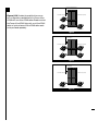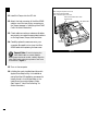
1
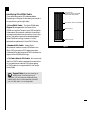
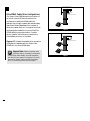
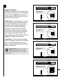
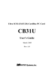
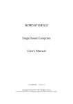
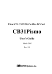
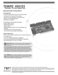
Installation Manual
Tempo™ Ultra ATA66 Macintosh PCI
Host Adapter
© 2000 Sonnet Technologies, Inc.
All rights reserved.
Sonnet Technologies, Inc.
15 Whatney
Irvine, California 92618-2808 USA
Toll Free Sales: 1-800-786-6260
Sales: 1-1-949-587-3500
Fax: 1-1-949-457-6350
Customer Service: 1-1-949-472-2772
(Monday–Friday, 8 am–5 pm Pacific Time)
Customer Service E-mail: [email protected]
Domestic Sales E-mail: [email protected]
Website: www.sonnettech.com
Sonnet, the Sonnet logotype, Simply Fast, the Simply
Fast logotype, and Tempo are trademarks of Sonnet
Technologies, Inc. Macintosh, Mac and the Mac logo
are trademarks of Apple Computer, Inc., registered in
the U.S. and other countries. Other product names are
trademarks of their respective owners. Product
specifications are subject to change without notice.
This manual may not be copied, in whole or
in part, without the written consent of Sonnet
Technologies, Inc. Your rights to software
distributed by Sonnet is governed by its
accompanying software license agreement.
Sonnet has made every effort to ensure the
accuracy of this manual. Product specifications are
subject to change without notice.
Manual Number: Z-TAT-066-MNL-T
Release: v 1.1a
Printed in the U.S.A.
Contents
Preface
Compatible Macintosh Models
Getting Started
v
vi
vii
About the Tempo Ultra ATA66
Identifying Ultra ATA66 Cable
Ultra ATA66 Cable/Drive
Configurations
viii
ix
x
1 Tempo Ultra ATA66 General
Installation Instructions
1-1
2 Configuring Your Hard Drive
2-1
Mounting Brackets
Jumper Block
Jumper Pin Settings
3 Hard Drive Initializing
Apple Drive Setup
2-3
2-3
2-5
3-1
3-3
Detailed Installation Instructions
for Power Macintosh Models
4 Power Macintosh Desktop
Installation
4-1
5 Power Macintosh Tower
Installation
5-1
6 Power Macintosh G3 Blue &
White or G4 Graphite
Installation
6-1
7 Troubleshooting Guide
7-1
8 Warranty
8-1
9 Contacting Customer Service
9-1
iii
Preface
This manual explains how to install the hardware
and software for the Sonnet Tempo™ Ultra ATA66
Macintosh® PCI Host Adapter. The Tempo Ultra
ATA66 allows you to install up to four internal
IDE hard drives (with the purchase of an additional ATA66 cable) into most PCI-based Power
Macintosh® computers, providing mass storage
options beyond SCSI to the larger, faster, and more
affordable Ultra ATA/66 hard drives.
This documentation assumes you have a working
knowledge of the Macintosh and its operating
conventions. If you are unfamiliar with the
Macintosh, see your computer’s documentation.
Support Note: Like most technologies,
IDE devices have their own vocabulary.
The following terms may be helpful as you read
this manual.
IDE (Integrated Drive Electronics) – A standard
electronic interface between a PCI-based system’s
memory and disk storage devices. EIDE, an
enhanced version of IDE, is commonly used in
PCI computers.
ATA (Advanced Technology Attachment) –
The “official” name used by the ANSI (American
National Standards Institute) to describe IDE
technology.
Ultra ATA/66 – Ultra ATA/66 is the latest drive
data transfer protocol used in today’s disk storage
devices. It incorporates ATA/IDE technology with
data transfer rates up to 66MB/sec, effectively
doubling the burst data rate of the previous
transfer protocol, Ultra ATA/33. Ultra ATA/66
provides greater system throughput and data
transfer integrity.
v
Compatible Macintosh Models
The following Power Macintosh and Mac® OS
compatible computers are supported with the
Sonnet Tempo Ultra ATA66:
• Power Macintosh 4400, 6400, 6500, 7200,
7220, 7300, 7500, 7600, 8200, 8500, 8515,
8600, 9500, 9515, 9600
• Power Macintosh G3 All-in-one, Blue &
White, Desktop, MiniTower, Server, Power
Macintosh G4 (PCI Graphics)
• Performa Series 64xx
• Workgroup Server 7250, 7350, 8550, 9650
• DayStar Genesis series
• Mactell XB-Pro
• Power Computing PowerBase Desktop and
Tower, PowerCenter, PowerCenter Pro,
PowerCurve, PowerTower, PowerTower Pro,
PowerWave
• StarMax 3000, 4000, 5000, 5500
• UMAX C500, C600, C600X, J700, S900
The Tempo Ultra ATA66 Compatibility Chart
(Figure 1) identifies the number of PCI slots and
expansion bays available in Tempo compatible
computers. Depending on your system configuration there may already be additional PCI cards
and/or drives installed in your computer. For hardware details on your particular computer model,
please refer to your computer’s user guide.
vi
Figure 1: Tempo Ultra ATA66
Compatibility Chart
Getting Started
Check Addendum Pages
For the most current information regarding the
Sonnet Tempo Ultra ATA66, read the addendum
pages that may be packaged with your product.
System Compatibility
At the time of the printing of this manual,
the Tempo Ultra ATA66 is compatible with System
7.5.3 through the latest Mac OS from Apple. For
up-to-date Mac OS compatibility, check our website.
Visit Our Website
The latest software updates and online support
files are available from the Sonnet website at
http://www.sonnettech.com.
Take Precautionary Measures
We recommend that you make a backup of important information on your system’s current hard
drive(s) prior to installing new hardware or software.
When handling computer products, you must take
care to prevent the components from being
damaged by static electricity. Always ground yourself
by working in an area free of static electricity and
avoid carpeted areas.
Familiarize Yourself with the
Instructions
Please familiarize yourself with the instructions in
this manual before beginning the installation. If you
feel you are unable to install the computer hardware, contact a qualified computer technician.
vii
About the Tempo Ultra ATA66
Tempo Ultra ATA66
Macintosh PCI Host Adapter
PCI Slot
We strongly recommend reading through this
entire manual if this is your first installation of the
hardware. The installation of the Tempo Ultra
ATA66 with additional internal IDE hard drives
requires that your computer have one available PCI
slot and, depending on the number of drives being
installed, unoccupied drive expansion bays.
Tempo supports a wide
range of PCI-based Macs.
Your PCI slot may vary from
this illustration.
Figure 1
Figure 1 illustrates the location and installation
of the Tempo Ultra ATA66 into a PCI slot; your
computer’s logic board and location of PCI slots
may differ from what is pictured.
Upper Drive
Expansion Bay
Figures 2-4 illustrate the location of drive expansion bays in popular desktop and tower-based
Power Macintosh computers.
Lower Drive
Expansion Bay
Figure 2
Upper Drive
Expansion Bay
Lower Drive
Expansion Bay
Figure 3
viii
Lower Drive
Expansion Bay
Figure 4
Identifying Ultra ATA66 Cable
There are three types of ATA cables available.
Depending on the type of drive being connected, it
is important to use the right cable.
• Ultra ATA66 Cable – The Ultra ATA66 cable
(Figure 5) packaged with the Tempo Ultra
ATA66 connects the Tempo to your IDE hard drive.
It features an 80-conductor cable with three 40-pin
connectors and allows the connection of up to two
drives. This cable is required to take advantage of
Ultra ATA/66 technology; however, it is fully
backward-compatible with Ultra ATA/33 drives.
• Standard ATA Cable – Uses a 40-pin,
40-conductor cable to connect IDE drives to the
40-pin IDE connectors of PCI-based computers.
A standard ATA cable supports ATA/33 but does not
support Ultra ATA/66 technology.
Host Connector
(connects to Tempo Ultra ATA66
Macintosh PCI Host Adapter)
80-conductor cable for Ultra ATA/66
Slave Connector
Master Connector
Figure 5
• CS (Cable Select) ATA Cable – Not commonly
used, the CS ATA cable is required when each drive
on the cable has an identical CS jumper setting.
A CS ATA cable is not supported with the Tempo
Ultra ATA66.
Support Note: If you are planning on
adding three or four drives to your
computer, you will require an additional Ultra
ATA66 cable, which is sold separately. DO NOT
use a CS ATA cable. It is not supported.
ix
Tempo Ultra ATA66 Macintosh
PCI Host Adapter
Ultra ATA66 Cable/Drive Configurations
The Tempo Ultra ATA66 allows the connection of
up to four internal IDE hard drives (with the
purchase of an additional ATA66 cable); for
example, two primary (master) and two secondary
(slave) hard drives. Regardless of the number of
drives, the master drive, or in the case of one drive,
must always be installed on the end of the Ultra
ATA66 cable for proper termination. If a slave
drive is installed, it should be connected to the
intermediate connector on the cable.
Figures 6-7 illustrate the possible drive connection
configurations available with the Tempo Ultra
ATA66 with one Ultra ATA66 cable.
Support Note: When an existing drive
(one with data on it already) is connected
to the Tempo Ultra ATA66, you must reinitialize
the drive for your system to recognize it. Since all
data will be erased, make a backup if necessary
prior to connecting the drive to the Tempo.
x
Ultra ATA66 Cable (included)
Drive 0
(Master or Single)
Figure 6
Tempo Ultra ATA66 Macintosh
PCI Host Adapter
Ultra ATA66 Cable (included)
Drive 1
(Slave)
Drive 0
(Master)
Figure 7
Tempo Ultra ATA66 Macintosh
PCI Host Adapter
Figures 8-10 illustrate the possible drive connection configurations available with the Tempo Ultra
ATA66 with two Ultra ATA66 cables. Please note that
the Tempo Ultra ATA66 ships with one Ultra ATA66
cable; an optional second Ultra ATA66 cable needs
to be purchased separately.
Ultra ATA66 Cable (optional)
Ultra ATA66 Cable (included)
Drive 1
(Slave)
Drive 2
(Single or Master)
Drive 0
(Master)
Figure 8
Tempo Ultra ATA66 Macintosh
PCI Host Adapter
Ultra ATA66 Cable (optional)
Ultra ATA66 Cable (included)
Drive 3
(Slave)
Drive 1
(Slave)
Drive 2
(Master)
Drive 0
(Master)
Figure 9
Tempo Ultra ATA66 Macintosh
PCI Host Adapter
Ultra ATA66 Cable (optional)
Ultra ATA66 Cable (included)
Drive 1
(Single or Master)
Drive 0
(Single or Master)
Figure 10
xi
Chapter 1
Tempo Ultra ATA66 General
Installation Instructions
This chapter contains instructions for installing
the Tempo Ultra ATA66 into most PCI-based computers. For more detailed installation instructions on
Power Macintosh Desktop, Tower, G3 Blue & White,
and G4 Graphite models, see Chapters 4-6.
Support Note: For certain computer
models, gaining access to the drive
expansion bays may require some technical
knowledge. We recommend you first consult you
computer’s user guide. If you feel you are unable
to install the computer hardware, contact a
qualified technician.
You Should Have
The following items should be included in your
product package:
• One Tempo Ultra ATA66 Macintosh PCI Host
Adapter
• One Ultra ATA66 cable
• Installation manual
For the installation you may require the
following items:
• Medium Philips screwdriver
• Small flatblade screwdriver
• Needle nose pliers
• Drive mounting brackets (if your computer
does not already have them) - sold separately
• An additional Ultra ATA66 cable - sold separately
(if 3 or 4 drives are being installed or 2 drives are
being installed as a master/master configuration)
1-1
Support Note: We recommend you
make a backup of important information
on your system’s current hard drive(s) prior to
installing new hardware or software. When
handling computer products, you must take care
to prevent components from being damaged by
static electricity. Always ground yourself by working in an area free of static electricity and avoid
carpeted areas. Handle the Tempo only by its
edges, and avoid touching connector traces and
component pins on PCI cards, hard drives, and
other IDE devices.
Tempo Ultra ATA66 Installation
To install the Tempo Ultra ATA66, follow these steps:
1. Shut down computer.
2. Remove the case cover from computer.
3. Remove the Tempo and Ultra ATA66 cable
from packaging materials.
4. Determine the number of hard drives that are
going to be installed inside your computer
with the Tempo. (See page x, “Ultra ATA66
Cable/Drive Configurations” for further
information.)
Support Note: When an existing drive
(one with data on it already) is connected
to the Tempo Ultra ATA66, you must reinitialize
the drive for your system to recognize it. Since all
data will be erased, make a backup if necessary
prior to connecting the drive to the Tempo.
1-2
5. Configure the hard drive with appropriate
jumper pin settings. If necessary, use a small
flatblade screwdriver or needle nose pliers to set
the jumper pins. (See Chapter 2, “Configuring
Your Hard Drive” for further information.)
6. Attach the primary/master connector of the
Ultra ATA66 cable to the hard drive. (See
page ix, “Identifying Ultra ATA66 Cable” for
further information.)
7. Depending on your computer model,
mount the hard drive to a drive mounting
bracket/carrier (Figure 1) or a drive sled
(Figure 2). You may require a medium
Philips screwdriver to perform the installation.
If necessary, refer to your computer’s user guide
for specific information on the installation
of internal storage devices.
Drive Mounting
Bracket/Carrier
Figure 1
Drive Sled
Figure 2
8. Install the hard drive into an expansion bay.
9. Attach a power cable connector to the hard
drive (there should be an additional
connector on the existing internal hard
drive’s power cable).
10. Locate an available PCI slot and remove
its access port cover (if present).
1-3
11. Install the Tempo into the PCI slot.
When closing the expansion card cover,
avoid crimping the Ultra ATA66
cable on the inner ridges of the cover.
Fold the Ultra ATA66 cable so it fits
within this area.
12. Attach the host connector of the Ultra ATA66
cable to one of the two 40-pin connectors on
the Tempo (see page ix, “Identifying Ultra ATA66
Cable” for further information).
Ultra ATA66 Cable
13. Check cable connections; make sure all cables
are properly connected to appropriate locations
on the logic board, Tempo, and hard drive.
14. Carefully replace the case cover onto your
computer. Be careful not to crimp the Ultra
ATA66 cable while replacing the case cover.
Expansion
Card Cover
Figure 3
Support Note: To avoid crimping the
Ultra ATA66 cable on certain desktopbased Power Macintosh models, carefully align the
Ultra ATA66 cable under the expansion card cover
as illustrated in Figure 3.
15. Turn on the computer.
16. Initialize the newly installed hard drive with
Apple’s Drive Setup utility. It is installed as
part of the Mac OS installation process and is
usually found in the Utilities folder on the
hard drive of your active System Folder.
(See Chapter 3, “Hard Drive Initializing” for
further information.)
1-4
Chapter 2
Configuring Your Hard Drive
Sonnet has tested the Tempo Ultra ATA66 with
popular IDE hard drives. The information and
examples in this chapter are provided to aid you in
configuring a hard drive. In addition, you may
need to refer to your hard drive’s user guide.
Support Note: When an existing drive
(one with data on it already) is connected
to the Tempo Ultra ATA66, you must initialize the
drive for your system to recognize it. Since all data
will be erased, make a backup if necessary prior to
connecting the drive to the Tempo.
2-1
Common Drive Jumper Settings
Mounting Brackets
Most drives need to be outfitted with mounting
brackets before being installed into a computer.
Please refer to our computer and/or drive’s user
guides for details.
Master
Jumper selection for the primary drive of two drives
installed on the same ATA cable
Master/Single
Jumper selection for the primary drive of two drives
installed on the same ATA cable (designated as only
master on some drives) / Jumper selection for a single
(primary) drive on an ATA cable.
Single
Jumper selection for a single (primary) drive on an
ATA cable
Slave
Jumper selection for the secondary drive of two drives
installed on the same ATA cable
Cable Select
Jumper selection for special drive cable configurations;
Rarely used and not supported with the Tempo
Jumper Block
Prior to installing a drive, you will need to configure
it as either a primary (master) or secondary (slave)
drive. Figure 1 lists common jumper settings.
Most drives are factory preset as a master drive. To
change the setting, you will need to reconfigure the
position of the jumpers located in the jumper block.
The jumper block is located at the rear of the drive
(Figure 2), or on the drive’s exposed printed circuit
board (Figure 3). The location of the jumper block
and position of jumper pins vary depending on the
manufacturer of the drive. Refer to your drive’s user
guide or the jumper setting information printed on
your drive.
Figure 1
Jumper block
Figure 2
Support Note: When configuring your
drive’s jumper pins, verify the orientation
of the drive with respect to the illustration. llustrations may vary.
Jumper block
Figure 3
2-2
8-pin Jumper
Connector
Jumper Pin Settings
Adjusting the jumper pins of a drive’s jumper block
designates the primary (master) or secondary (slave)
settings of the drive. Figures 4-7 illustrate four of
the more common hard drive settings. Your drive
may differ from those pictured.
• Master Drive – The master drive (or in the case
of one drive) must always be installed on the end
of the Ultra ATA66 cable for proper termination.
Most drives are factory preset as a master drive.
Normally you do not need to reconfigure the
jumper pins of a master drive since it is already
preconfigured; however, if you are installing only
one drive, and its jumpers allow you to set it with
either a master or single setting (similar to the
setting illustrated for the Western Digital hard drive
in Figure 7), configure it as a single drive.
• Slave Drive – If a secondary drive is installed
onto the intermediate connector of an Ultra ATA66
cable, it is considered a slave drive and must be
properly configured by adjusting the jumper pins of
the drive’s jumper block.
Support Note: Make sure to properly
configure the jumper pins of the hard
drive(s) for your system set-up, or your computer
may not boot.
40-pin IDE Connector
4-pin Power
Connector
Manufacturer: IBM
Model: DJNA-352500
Master
or Single
= Jumper On
Slave
= Jumper Off
Figure 4
8-pin Jumper
Connector
40-pin IDE Connector
4-pin Power
Connector
Manufacturer: Quantum
Model: Fireball™ lct
Master/
Single
= Jumper On
Slave
= Jumper Off
Figure 5
8-pin Jumper
Connector
40-pin IDE Connector
4-pin Power
Connector
Manufacturer: Seagate
Model: ST320423A
Master/
Single
= Jumper On
Slave
= Jumper Off
Figure 6
10-pin Jumper
Connector
40-pin IDE Connector
Manufacturer: Western Digital
Model: WD Caviar™ 272AA
4-pin Power
Connector
Single
Master
= Jumper On
Slave
= Jumper Off
Figure 7
2-3
Chapter 3
Hard Drive Initializing
For your computer to properly recognize a hard
drive it will need to be initialized with drive
formatting software. The Mac OS includes Drive
Setup, a drive formatting utility, which will be adequate for initializing your hard drive. Alternatively,
you can use third party drive formatting software.
3-1
Apple Drive Setup
The Apple Drive Setup utility allows you to initialize
an unformatted hard drive. The utility is installed
as a part of the Mac OS installation process and is
usually installed in the Utilities folder on the hard
drive of your active System Folder. As of version 1.4,
Drive Setup supports the formatting of Apple’s
brand of hard drives as well as drives from third
party manufacturers. We recommend using the
latest version of Drive Setup which is available
from Apple’s website at http://asu.info.apple.com/
Figure 1
To format your drive, follow these steps:
1. Double-click the Apple Drive Setup utility
icon to run the utility.
2. Select the drive you wish to format from
the Drive Setup window (Figure 1). A new
uninitialized hard drive will show up as
not initialized.
Figure 2
Support Note: An IDE hard drive
attached to the Tempo Ultra ATA66
will register as a SCSI device to the computer. For
example, in Figure 1 the newly installed hard drive
shows up as <not initialized> under Volume
Name(s) and SCSI under Type.
3. From Functions in the menu bar, select
Initialization Options… (Figure 2).
Figure 3
4. The Initialization Options window will appear
(Figure 3). Select Low Level Format and click
OK to begin formatting the drive.
Support Note: A low level format is not
usually necessary with a new/uninitialized
drive; in general, this step ensures that bad blocks
of data are mapped out on the drive.
3-2
After the hard drive is initialized you can either
partition the drive or quit the Drive Setup utility to
begin using the drive. Partitioning a drive effectively
creates separate volumes (“disks”) that mount to
the desktop. For example, you could partition the
drive into two volumes, one for applications and
one for documents. Partitioning also reinitializes
(erases) the drive, so it is best to do it prior to saving
applications and files to it. For further information
on partitioning, refer to Drive Setup Help from
Help in the menu bar.
3-3
Chapter 4
Power Macintosh Desktop Installation
This chapter contains instructions for installing the
Tempo Ultra ATA66 into a desktop-based Power
Macintosh (such as the Power Macintosh 7300,
7500, 7600). If your computer does not resemble
those pictured in this chapter, or you would prefer
a quick install approach, refer to the general
installation instructions in Chapter 1.
Getting Started
We suggest you inventory and arrange the
following items in front of you prior to proceeding
with the installation:
• Tempo Ultra ATA66 Macintosh PCI Host Adapter
• Ultra ATA66 cable
• IDE hard drive
• Medium Philips screwdriver
• Small flatblade screwdriver
• Needle nose pliers
Support Note: We recommend you
make a backup of important information
on your system’s current hard drive(s) prior to
installing new hardware or software. When
handling computer products, you must take care
to prevent components from being damaged by
static electricity. Always ground yourself by
working in an area free of static electricity and
avoid carpeted areas. Handle the Tempo only by
its edges, and avoid touching connector traces
and component pins on PCI cards, hard drives,
and other IDE devices.
Support Note: When an existing drive
(one with data on it already) is connected
to the Tempo Ultra ATA66, you must reinitialize
the drive for your system to recognize it. Since all
data will be erased, make a backup if necessary
prior to connecting the drive to the Tempo.
4-1
Shut Down and Open Computer
1. Shut down your Power Macintosh. If the
computer has been on for any length of time,
wait a few minutes for it to cool before
beginning the installation.
2. Disconnect the power and peripheral cables
from the back of the computer and move it to
an area where you can freely work.
3. With the front of the computer facing you,
remove the case cover from your Power
Macintosh. Locate the two switches on the
underside of the front cover, depress them,
and slide the cover forward and off the
computer (Figure 1).
4. Identify the internal components of your
computer. Touch the power supply metal
shielding (Figure 2) to discharge potential
damaging static electricity, and rotate the
expansion card cover up and to the left
(Figure 2).
Figure 1
power supply
metal shielding
expansion card cover
Figure 2
lower expansion bay
5. Determine the expansion bay where you will
install the hard drive. For the purposes of these
instructions, the hard drive will be installed
into the lower expansion bay (Figure 3).
drive bay bevel
6. Orient the hard drive, mounting bracket, and
mounting bracket screws in front of you
(Figure 4). Configure the hard drive for your
computer set-up. If necessary, use a small
flatblade screwdriver or a needle nose plier to
adjust the jumper pins. For further information
on jumper pin settings, see Chapter 2,
“Configuring Your Hard Drive.”
4-2
Figure 3
7. Mount the hard drive to the drive mounting
bracket with the screws provided with the
bracket or hard drive. You may require a Philips
screwdriver to perform the installation.
Figure 4
8. Starting with the host connector (at the longer
end of the Ultra ATA66 cable), thread the
Ultra ATA66 cable through the opening of the
lower expansion bay and into the interior of
the computer (Figure 5); if you are unfamiliar
with the Ultra ATA66 cable connectors, see
page ix, for further information.
9. Attach the primary/master connector on
the Ultra ATA66 cable to the hard drive
(Figure 6); if you are unfamiliar with the
Ultra ATA66 cable connectors, see page ix,
for further information. Slide the drive into
the drive bay.
10. The current internal hard drive’s power cable
should have an additional drive power
connector (Figure 7). Attach the power
connector to the newly installed hard drive.
Ultra ATA66 cable
Figure 5
Ultra ATA66 cable
hard drive
Figure 6
Install Tempo Ultra ATA66
1. Select an available PCI slot to install the Tempo
and remove its access port cover (Figure 8).
2. Remove the Tempo from the anti-static
package, making sure to handle the board
by the edges.
additional drive
power connector
current internal hard
drive’s power connector
Figure 7
access port cover
4-3
Figure 8
Tempo
3. Align the Tempo over the PCI slot (Figure 9).
Gently press down until it is firmly seated into
the PCI slot, taking care not to wiggle the
board as you install it into the slot.
4. Attach the host connector on the Ultra ATA66
cable to the connector closest to the bracket on
the Tempo (Figure 10); if you are unfamiliar
with the Ultra ATA66 cable connectors, see
page ix, for further information.
Figure 9
Close Computer
Ultra ATA66 cable
1. Carefully position the Ultra ATA66 cable inside
the computer as to avoid crimping it by the
expansion card cover (see page 1-4, Figure 3 for
illustration). Rotate the expansion card cover
into place over the PCI slots (Figure 11).
2. Replace the case cover onto your computer
(Figure 12).
Figure 10
3. Return the computer to your computing area
and reconnect the power and peripheral cables
to the computer.
Turn On Computer
1. Turn on your Power Macintosh.
2. For your computer to properly recognize a
new hard drive, you will need to initialize
it. Refer to Chapter 3, “Hard Drive Initializing”
for further instructions.
Figure 11
4-4
Figure 12
Chapter 5
Power Macintosh Tower Installation
This chapter contains instructions for installing the
Tempo Ultra ATA66 into a tower-based Power
Macintosh (such as the Power Macintosh 8600,
9600). If your computer does not resemble those
pictured in this chapter, or you would prefer a quick
install approach, refer to the general installation
instructions in Chapter 1.
Getting Started
We suggest you inventory and arrange the
following items in front of you prior to proceeding
with the installation:
• Tempo Ultra ATA66 Macintosh PCI Host Adapter
• Ultra ATA66 cable
• IDE hard drive
• Medium Philips screwdriver
• Small flatblade screwdriver
• Needle nose pliers
Support Note: We recommend you
make a backup of important information
on your system’s current hard drive(s) prior to
installing new hardware or software. When
handling computer products, you must take care
to prevent components from being damaged by
static electricity. Always ground yourself by
working in an area free of static electricity and
avoid carpeted areas. Handle the Tempo only by
its edges, and avoid touching connector traces
and component pins on PCI cards, hard drives,
and other IDE devices.
Support Note: When an existing drive
(one with data on it already) is connected
to the Tempo Ultra ATA66, you must reinitialize
the drive for your system to recognize it. Since all
data will be erased, make a backup if necessary
prior to connecting the drive to the Tempo.
5-1
Shut Down and Open Computer
1. Shut down your Power Macintosh. If the
computer has been on for any length of time,
wait a few minutes for it to cool before
beginning the installation.
2. Disconnect the power and peripheral cables
from the back of the computer and move it to
an area where you can freely work.
Figure 1
drive mounting
bracket
3. With the front of the computer facing you,
open your Power Macintosh by removing the
side panel. Depress the green button and lower
the panel away from the computer’s case
(Figure 1).
4. Determine the expansion bay where you will
install the hard drive and remove the front
bevel piece. In Figure 2, the lower drive
expansion bevel has been removed.
drive bay bevel
Figure 2
5. Slide the hard drive mounting bracket forward
and out of the expansion bay (Figure 2).
You may need to pull firmly on the bracket.
6. Orient the hard drive, mounting bracket, and
mounting bracket screws in front of you
(Figure 3). Configure the hard drive for your
computer set-up. If necessary, use a small
flatblade screwdriver or a needle nose plier to
adjust the jumper pins. For further information
on jumper pin settings, see Chapter 2,
“Configuring Your Hard Drive.”
7. Mount the hard drive to the drive mounting
bracket with the screws provided with the
bracket or hard drive. You may require a Philips
screwdriver to perform the installation.
5-2
Figure 3
access port cover
Install Tempo Ultra ATA66
1. Select an available PCI slot to install the Tempo
and remove its access port cover (Figure 4).
2. Remove the Tempo from the anti-static
package, making sure to handle the board
by the edges.
3. Attach the host connector on the Ultra ATA66
cable to the connector closest to the bracket on
the Tempo (Figure 5); if you are unfamiliar
with the Ultra ATA66 cable connectors, see
page ix, for further information.
Figure 4
bracket
4. Align the Tempo over the PCI slot (Figure 6).
Gently press down until it is firmly seated in
the PCI slot, taking care not to wiggle the
board as you install it into the slot.
Figure 5
5. The current internal hard drive’s power cable
should have an additional drive power
connector. Thread the power connector along
with the Ultra ATA66 cable through the
opening of the drive sled (Figure 7).
Tempo
PCI slot
Figure 6
Ultra ATA66 cable
additional power
connector
opening in
drive sled
5-3
Tempo
Figure 7
additional drive
power connector
Ultra ATA66 cable
6. Work the power connector along with the
Ultra ATA66 cable into the expansion bay
(Figure 8).
7. Attach the power connector and the
primary/master connector on the Ultra ATA66
cable to the hard drive (Figure 9); if you are
unfamiliar with the Ultra ATA66 cable connectors, see page ix, for further information.
8. Slide the hard drive into the expansion bay
(Figure 10).
Figure 8
additional drive
power connector
Ultra ATA66 cable
Close Computer
1. Carefully position the Ultra ATA66 cable inside
the computer as to avoid crimping it by the
case cover and replace the side panel onto your
Power Macintosh (Figure 11).
2. Return the computer to your computing area
and reconnect the power and peripheral cables
to the computer.
Turn On Computer
Figure 9
hard drive
1. Turn on your Power Macintosh.
2. For your computer to properly recognize a
new hard drive, you will need to initialize
and format it. Refer to Chapter 3, “Hard
Drive Initializing” for further instructions.
Figure 10
5-4
Figure 11
Chapter 6
Power Macintosh G3 Blue & White or
G4 Graphite Installation
This chapter contains instructions for installing the
Tempo Ultra ATA66 into a tower-based Power
Macintosh (such as the Power Macintosh G3 Blue &
White or G4 Graphite). If your computer does not
resemble those pictured in this chapter, or you
would prefer a quick install approach, refer to the
general installation instructions in Chapter 1.
Getting Started
We suggest you inventory and arrange the
following items in front of you prior to proceeding
with the installation:
• Tempo Ultra ATA66 Macintosh PCI Host Adapter
• Ultra ATA66 cable
• IDE hard drive
• Medium Philips screwdriver
• Small flatblade screwdriver
• Needle nose pliers
Support Note: We recommend you
make a backup of important information
on your system’s current hard drive(s) prior to
installing new hardware or software. When
handling computer products, you must take care
to prevent components from being damaged by
static electricity. Always ground yourself by
working in an area free of static electricity and
avoid carpeted areas. Handle the Tempo only by
its edges, and avoid touching connector traces
and component pins on PCI cards, hard drives,
and other IDE devices.
Support Note: When an existing drive
(one with data on it already) is connected
to the Tempo Ultra ATA66, you must reinitialize
the drive for your system to recognize it. Since all
data will be erased, make a backup if necessary
prior to connecting the drive to the Tempo.
6-1
Shut Down and Open Computer
security lock
1. Shut down your Power Macintosh. If the
computer has been on for any length of time,
wait a few minutes for it to cool before
beginning the installation.
2. Disconnect the power and peripheral cables
from the back of the computer and move it to
an area where you can freely work.
Figure 1
3. Locate the security lock at the back of the
computer (Figure 1). If it is not already
pressed in, do so now.
4. With the right side of the case facing you, open
your Power Macintosh by lifting the release
latch and lowering the side panel away from
the computer’s case (Figure 2).
5. Touch the power supply metal shielding
(Figure 3) to discharge any potential static
electricity.
Raise release latch
Figure 2
power supply
metal shielding
Figure 3
6-2
internal expansion
bay area
6. Locate the lower internal expansion bay area
of the computer (Figure 4). For specific
details, refer to your computer’s user manual.
For Power Macintosh G3 Blue & White
built after June 1999 and G4 Graphite
models: There are three drive carriers located
on the floor of the cabinet. Depending on your
computer model, you may need to disconnect
the power cord bundle and internal hard drive
ribbon cable (Figure 4) prior to removing a
carrier. To mount a drive to a drive carrier,
locate an unoccupied carrier and remove the
single attachment screw found at the rear of
the carrier. Detach and remove the carrier from
the computer.
For Power Macintosh G3 Blue & White
models built before June 1999: There is
a single drive sled that occupies the floor of
the cabinet. To mount a drive to the drive sled,
you will need to temporarily remove the drive
sled from the computer. First, remove the
drive sled attachment screw next to the
internal hard drive (Figure 5). Then, disconnect the power cord bundle and internal hard
drive ribbon cable from the logic board
(Figure 6). Once all the cables are clear,
CAREFULLY remove the drive sled from the
computer (Figure 7).
internal hard drive
ribbon cable
power cord
bundle
Figure 4
drive sled
attachment screw
Figure 5
internal hard drive
ribbon cable
power cord
bundle
Figure 6
6-3
Figure 7
Mount Drive to Drive Carrier or Sled
1. Using a small flatblade screwdriver or a
needle nose plier, properly configure the hard
drive jumper pins. For further information
on jumper pin settings, see Chapter 2,
“Configuring Your Hard Drive.”
2. Depending on your computer model, mount
the new drive to either the single drive carrier
or drive sled with appropriate screws. Attach
the primary/master connector on the Ultra
ATA66 cable to the hard drive; if you are unfamiliar with the Ultra ATA66 cable connectors,
see page ix, for further information. Figure 8
illustrates a new drive with attached Ultra
ATA66 cable mounted onto a drive sled.
3. Reinstall the drive carrier or drive sled into the
computer and attach a drive power connector
to the new drive. The internal hard drive’s
power cable should have an additional power
connector. If disconnected earlier, reconnect
the logic board power bundle and internal
hard drive ribbon cable to the logic board.
Your system should appear similar to what is
shown in Figure 9 after everything is
reinstalled and reconnected.
6-4
Figure 8
new IDE
hard drive
internal
hard drive
internal hard drive
ribbon cable
power cord
bundle
Figure 9
Install Tempo Ultra ATA66
access port cover
1. Select an available PCI slot to install the Tempo
and remove its access port cover (Figure 10).
2. Remove the Tempo from the anti-static
package, making sure to handle the board by
the edges.
3. Align the Tempo over the PCI slot
(Figure 11). Gently press down until it is
firmly seated in the PCI slot, taking care not
to wiggle the board as you install it into
the slot.
4. Attach the host connector on the Ultra ATA66
cable to the connector closest to the bracket on
the Tempo (Figure 12); if you are unfamiliar
with the Ultra ATA66 cable connectors, see
page ix, for further information.
Figure 10
Tempo
Figure 11
Close Computer
1. Carefully position the Ultra ATA66 cable inside
the computer as to avoid crimping it by the
case cover and replace the side panel onto
your Power Macintosh (Figure 13).
Ultra ATA66 cable
2. Return the computer to your computing area
and reconnect the power and peripheral cables
to the computer.
Turn On Computer
Figure 12
1. Turn on your Power Macintosh.
2. For your computer to properly recognize a
new hard drive, you will need to initialize
and format it. Refer to Chapter 3, “Hard
Drive Initializing” for further instructions.
6-5
Figure 13
Chapter 7
Troubleshooting Guide
Problem: Hard drive(s) connected to the Tempo
do not mount (appear on the desktop).
Possible Solutions:
1) Your hard drive’s jumpers may be improperly
configured. Refer to Chapter 2, “Configuring
Your Hard Drive,” for complete information
about reconfiguring the jumpers on the jumper
block of your drive(s).
2) The Ultra ATA66 cable(s) may not be connected
to the Tempo or hard drive(s) properly. Refer to
“Getting Started” and the sections entitled
“Identifying Ultra ATA66 Cable,” and “Ultra
ATA66 Cable/Drive Configurations” for complete
information about connecting hard drives to
the Tempo.
3) The Ultra ATA66 cable may have been damaged
when you installed it. Follow the directions you
used for opening your computer, then examine
the cable for any signs of damage, including
crimping and piercing. If the cable is damaged,
you should replace it.
7-1
Chapter 8
Warranty
Sonnet Technologies, Inc. warrants that its product(s) shall
be free from defects in materials and workmanship for a
period of three years following the date of original
purchase. Sonnet’s liability under this warranty shall be
limited, at its option, to repairing or replacing product(s)
shown to be defective either in materials or workmanship.
The sole and exclusive remedy under this warranty shall
be such repair or replacement.
A claim of defective materials or workmanship in
product(s) shall be allowed only when it is submitted to
Sonnet within the warranty period. No claim shall be
allowed in respect to product(s) which have been altered,
neglected, damaged or stored in any manner which
adversely affects them. No product(s) shall be returned to
Sonnet for any reason without a return authorization from
Sonnet. You bear the responsibility for shipping product(s)
to Sonnet within 30 days of authorization and paying for
associated shipping and insurance costs. Sonnet will pay
the cost to ship repaired or replaced product(s) back to you.
This warranty shall also apply to product(s) that replace
defective product(s) but only for the original warranty
period. The warranty period shall not be extended by
reason of defect, or any period of time during which the
product(s) are not available to you because of defects,
without the express written consent of Sonnet.
EXCEPT FOR THE EXPRESS WARRANTY AGAINST
DEFECTS IN MATERIALS AND WORKMANSHIP CONTAINED HEREIN, SONNET MAKES NO WARRANTY OF
ANY KIND WHATSOEVER, EXPRESS OR IMPLIED, AND
ALL WARRANTIES OF MERCHANTABILITY AND
FITNESS FOR A PARTICULAR PURPOSE ARE HEREBY
DISCLAIMED BY SONNET. Without limitation of the
foregoing, Sonnet expressly disclaims any liability
whatsoever for any damages incurred, directly or
indirectly, in connection with its product(s), including
without limitation, loss of profits and special, incidental
or consequential damages, whether caused by Sonnet’s
negligence or otherwise.
8-1
Chapter 9
Contacting Customer Service
The Sonnet website (http://www.sonnettech.com)
has the most current support information and
technical updates.
Before you call Sonnet Customer Service please:
• Check our website for the latest
updates and online support files
• Check your manual for helpful
information
When you call Sonnet Customer Service, have
the following information available so one of our
representatives can better assist you:
• Product name
• Serial number
• Date of purchase
• Place of purchase
• Computer type and model
• Operating system and version
If further assistance is needed, please contact us at:
Sonnet Customer Service
Tel: 1-1-949-587-3500
(Monday–Friday, 8 am–5 pm Pacific Time)
Fax: 1-1-949-457-6350
E-mail: [email protected]
9-1