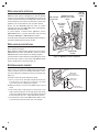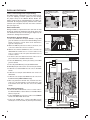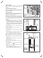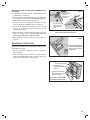
1
PRINTER’S INSTRUCTIONS:
INSTR,INSTL,DMC3-4 - LINEAR P/N: 10002226 A - INK: BLACK - MATERIAL: 20 LB. MEAD BOND - SIZE: 8.500” X 11.000” - SCALE: 1-1 - FOLDING: ALBUM FOLD - BINDING: SADDLE STITCH
INTRODUCTION
Designed to update older intercom systems, the DMC3-4 is a whole-house music and communication system that uses
your existing intercom 3 or 4 conductor system wire. It is designed to provide years of enjoyment and service to the
homeowner. M&S Systems brand audio products are backed with more than 50 years of experience in the design and
manufacture of precision acoustical equipment for the home. To ensure that the homeowner receives the high-quality
music and voice reproduction that the system is designed to deliver, it is important that each step of the installation be
carefully completed by the installer. In the event you need troubleshooting assistance, please call our technical support
staff at 1-800-421-1587.
DMC3-4 MUSIC/COMMUNICATIONS SYSTEM
INSTALLATION INSTRUCTIONS
CAUTION !
The exclamation point within an equilateral triangle is
intended to alert the user to the presence of important
operating and maintenance (servicing) instructions in the
literature accompanying the product.
SHOCK HAZARD !
The lightning flash with arrowhead symbol within an
equilateral triangle is intended to alert the user to the
presence of un-insulated “dangerous voltage” within the
product’s enclosure that may be of sufficient magnitude to
constitute a risk of electric shock to persons.
IMPORTANT SAFETY INSTRUCTIONS
Read Instructions - All the safety and operating
instructions should be read before installing or operating
the DMC3-4.
Retain Instructions - The safety and operating
instructions should be retained for future reference.
Heed Warnings - All warnings on the appliance and in the
operating instructions should be adhered to.
Follow Instructions - All operating and use instructions
should be followed.
Water and Moisture - The appliance should not be used
near water - for example: near bathtub, washbowl, kitchen
sink, laundry tub, in a wet basement, or near a swimming
pool, and the like. Doing so can create a fire or shock
hazards and impair the warranty.
Cleaning - Use only a dry cloth.
Attachments - Do not use attachments not recommended
by the product manufacturer as they may cause hazards.
Ventilation - The appliance should be situated so that
its location or position does not interfere with its proper
ventilation. For example, the appliance should not be
situated on a bed, sofa, rug, or similar surface that may
block the ventilation openings: or, placed in a built in
installation, such as a bookcase or cabinet that may
impede the flow of air to the ventilation openings.
Heat - The appliance should be situated away from heat
sources such as radiators, heat registers, stoves, or other
appliances (including amplifiers) that produce heat.
Power Sources - The appliance should be connected to
a power supply only of the type described in the rough-in
instructions or as marked on the appliance.
Grounding or Polarization - Precautions should be
taken so that the grounding or polarization means of an
appliance is not defeated.
Power Lines - An outdoor antenna should be located
away from power lines.
Outdoor Antenna Grounding - If an outside antenna
is connected to the receiver, be sure the antenna system
is grounded so as to provide some protection against
voltage surges and built up static charges. Section 810
of the National Electrical Code, ANSI/NFPA No. 70 1984,
provides information with respect to proper grounding of
the mast and supporting structure, grounding of the lead
in wire to an antenna discharge unit, size of grounding
conductors, location of antenna discharge unit, connection
to grounding electrodes, and requirements for the
grounding electrode (see figure).
Object and Liquid Entry - Never push objects of any
kind into this product through openings as they may touch
dangerous voltage points or short out parts that could
result in a fire or electric shock. Never spill liquid of any
kind on the product.
Servicing - The user should not attempt to service
the appliance beyond that described in the operating
instructions. All other servicing should be referred to
qualified service personnel.
Damage Requiring Service - The appliance should be
serviced by qualified service personnel when:
■ The power supply cord or the plug has been
damaged; or
■
Objects have fallen, or liquid has been spilled
into the appliance; or
■
The appliance has been exposed to rain; or the
appliance does not appear to operate normally
or exhibits a marked change in performance; or
■
The appliance has been dropped, or the
enclosure damaged.
■
When the product exhibits a distinct change in
performance - this indicates a need for service.
Replacement Parts - When replacement parts are
required, be sure the service technician has used
replacement parts specified by the manufacturer or have
the same characteristics as the original part. Unauthorized
substitutions may result in fire, electric shock, or other
hazards.
Safety Check - Upon completion of any service or repairs
to this product, ask the service technician to perform safety
checks to determine that the product is in proper operating
condition.
Wall or Ceiling Mounting - The product should be
mounted to a wall or ceiling only as recommended by the
manufacturer.
USA & Canada (800) 421-1587 & (800) 392-0123
(760) 438-7000 - Toll Free FAX (800) 468-1340
www.linearcorp.com
TABLE OF CONTENTS
Installation Overview . . . . . . . . . . . . . . . . . . . . . . . . . . .
Develop the Job Estimate . . . . . . . . . . . . . . . . . . . . . . .
Removing the Old System . . . . . . . . . . . . . . . . . . . . . . .
Installing the Wall Housing . . . . . . . . . . . . . . . . . . . . . .
Transformer Installation . . . . . . . . . . . . . . . . . . . . . . . . .
Replacing the Room Stations . . . . . . . . . . . . . . . . . . . .
Replacing Patio Stations . . . . . . . . . . . . . . . . . . . . . . . .
1
2
2
3
4
5
6
Replacing Door Stations . . . . . . . . . . . . . . . . . . . . . . . . 6
External Music Source . . . . . . . . . . . . . . . . . . . . . . . . . 6
Installing the Chime Module . . . . . . . . . . . . . . . . . . . . . 7
Optional Door Release Relay . . . . . . . . . . . . . . . . . . . . 7
Installing the DMC3-4 . . . . . . . . . . . . . . . . . . . . . . . . . . 8
Appendix A - Retrofit Compatibility Table . . . . . . . . . . 12
2-Year Limited Warranty . . . . . . . . . . . . . . . . . . . . . . . 13
IMPORTANT DO’S & DON’TS
✔ DO ensure that all instructions have been followed before power is applied to
system. The installation shall be carried out in accordance with all applicable
installation rules.
✔ DO use only M&S systems brand cable (except for Cat-5 & RG-6) as called
out in these instructions. The cable is designed and constructed with electrical
specifications necessary for proper audio performance.
✔ DO use only a dry cloth to clean the exterior plastics on the DMC3-4 Master
Station and Room Stations. DO NOT use liquid or aerosols.
✔ DO make gradual bends of the cable where necessary -- no sharper than 1” radius.
✔ DO dress the cables neatly with cable ties or Velcro™ wraps. Use loose or
moderate pressure.
✔ DO use cable-pulling lubricant only for cable runs that may otherwise require great
force to install. When cable lubricant is used, read the instructions to be sure it is
compatible with the cable jacket material (PVC or FEP).
✔ DO avoid stressing cable conductors, limit pulling tension to 25 pounds or less
as specified by EIA/TIA-568A standard. Pull cables gradually and with constant
tension, taking care not to crush or pinch bundles.
✔ DO use grommets to protect the cable where passing through metal studs or
anything that can possibly damage them.
✔ DO test every installed cable run with a cable tester. “Toning” alone is not acceptable.
✔ DO label every termination point. Use a unique identifier for each cable run. It will
make moves, adds, changes, and troubleshooting easier.
✔ DO support horizontal cable bundles using board supports, J-hooks, or cable trays.
✔ DO have signal cables cross at right angles to power cables to minimize induced
interference.
✔ DO always obey all local and national fire and building codes. Be sure to “firestop”
all cables that penetrate a firewall. Use plenum-rated cable where mandated.
WIRING CAUTIONS
● A licensed electrician must run a 120 VAC line from A DEDICATED 15-AMP
BREAKER to the DMC3-4 (and DMCMP3, if equipped) transformer(s).
● Use existing wire or suggested replacement wire for all DMC3-4 wire runs
excluding Door Station wire runs. For Door Stations, use the M&S Systems brand
MS4DCXSC wire that is included with the DMC1H or DMC1HC wall housing kits.
● Individual wire runs should not exceed 350 feet from any single room or Door
Station to the DMC3-4 Master Station or 1000 feet total for the entire system.
● Label all wire runs. Connecting the wires to the DMC3-4 Master Station, Room
Station, or Door Station incorrectly may result in system damage.
● Run a single cable from the Master Station unit location to each Room Station
and Door Station in a “home run” fashion. Do not loop cable from one Room
Station to another.
● DO NOT STAPLE CABLES. Staples cause shorts.
● DO NOT SPLICE CABLES. Splices are unreliable and defeat the signal
isolation properties of the cable.
● KEEP CABLES, ROOM STATIONS, AND PATIO STATIONS AT LEAST
18 INCHES FROM FLUORESCENT LIGHT FIXTURES, DIMER CONTROLS,
AND ALL OTHER WIRING. This includes AC wiring, security cable, and other
control wires. These can cause a “hum” or “buzzing” sound.
● Keep cables away from objects such as heating and air conditioning ducts,
metal construction plates, and anything else with sharp edges that can damage
the cables.
✔ DO follow the grounding and bonding requirements established by Electrical Code
TIA standard 607, and equipment manufacturer’s specifications.
✔ DO NOT locate the DMC3-4 Master Station or Room Stations in an exterior wall.
✔ DO NOT locate the DMC3-4 Master Station or Room Stations in any wall cavity
with any other electrical wiring in the cavity.
✔ DO NOT locate Patio Stations in places with direct exposure to sun and weather or
in locations that receive direct water spray.
✔ DO NOT attach non line-level audio devices or non M&S authorized equipment to
the system.
✔ DO NOT power up Master Station until all speakers and stations are connected.
✔ DO NOT splice or repair cables damaged during wire pulling, install a new cable.
✔ DO NOT coil or bundle the cables. This can cause electronic feedback.
✔ DO NOT over-tighten the screws for the volume controls, speakers, or the intercom
Master Station to prevent cracking.
✔ DO NOT install any station or speaker cables inside the 120 VAC transformer
enclosure.
✔ DO NOT tie cables to electrical conduits or lay cables on electrical fixtures. Keep
cables at least 16” away from fluorescent lights, HID light fixtures, or dimmers.
✔ DO NOT allow the cable to be sharply bent or kinked at any time.
✔ DO NOT install cables “taught” in the ceiling or elsewhere. A good installation
should have cables loose, but never sagging.
✔ DO NOT run signal cables parallel to power cables without adequate separation to
minimize induced interference.
✔ DO NOT exert more than 25 pounds of tension on 4-pair cables.
✔ DO NOT step on Cat-5 cable during installation.
✔ DO NOT overtighten the cable ties, apply cable ties loosely, with random spacing.
✔ DO NOT untwist the wire pairs in Cat-5 cable more than 1/2” to avoid crosstalk.
ROOM STATION CAUTIONS
Careful consideration should be used when determining the location
of the Room Stations. DO NOT install these devices in the following
locations:
✔ DO NOT install Room Stations near air return ducts.
✔ DO NOT install Room Stations in exterior walls. Insulation materials will change
speaker range and efficiency. Temperature changes in the wall will reduce
speaker life.
✔ DO NOT install Room Stations in saunas. They will not withstand the extreme
heat and moisture.
✔ DO NOT install Room Stations underneath cabinets or over counter tops.
✔ DO NOT install Room Stations in stud cavities with other wiring or appliances.
✔ DO NOT install Room Stations within 10 feet of other Room Stations or the
DMC3-4 Master Station unit. This will cause acoustical feedback.
✔ DO NOT install Room Stations in stud cavities with other Room Stations or the
DMC3-4 Master Station unit. This will cause acoustical feedback.
✔ DO NOT install Room Stations facing other Room Stations or the DMC3-4
Master Station unit. This will cause acoustical feedback.
Be sure that all Room Station mounting rings are level and oriented
as shown in these instructions.
Failure to adhere to these instructions can cause equipment
malfunction and void any warranty covered by Linear LLC.
The following tools are required for the DMC3-4 installation.
You may not need to use all these tools on each install but
having then handy will make the overall installation process
easier. The use of these or other tools is dependent on the
existing intercom system installation:
INSTALLATION OVERVIEW
The DMC3-4 retrofit installation is completed using the
following steps:
•
•
•
•
Develop the job estimate
Removal of the old intercom system
Install the DMC1H or DMC1HC housing
Replace the room and patio stations (NOTE: Do not remove the
existing room and patio station mounting rings)
• Replace the door station(s) (NOTE: Do not remove the door station
mounting enclosure)
• Install the DMC3-4 master and make all room, patio, and door station
connections
• Install the optional DMCMP3 CD/MP3 player
• Test the system
✔ NOTE: All retrofit installations with existing “loop” wiring (master to
station, station to station) must be replaced with “home run” wiring
(master to each station).
Door Release
Mechanism
#2 Phillips screwdriver
Wire stripper/cutter
Tape measure
Level
Tin snips
Digital multimeter (DMM)
Small (or precision size) Philips and flat head screwdrivers
Power drill with 1” auger
Small crowbar
Large flat head screwdriver
Rubber mallet
Extension cord
Wood chisel
Dry wall saw
DMC3R (3-wire)
DMC4R (4-wire)
Standard Room Station
Remote Power
Transformer
DRW
NR8P
8" Flush Mount
Speaker
•
•
•
•
•
•
•
•
•
•
•
•
•
•
RT11
DMC3RS (3-wire)
DMC4RS (4-wire)
Standard Room Station
Security Panel
NR8P
8" Flush Mount
Speaker
Dry Contact
Closure for
Door Release
(NR8-5)
Either
Dry Contact
Closure for
Panic Operation
(DMCFR)
Antennas
Included with
Wall Housings
AM
FM
DMC3RW (3-wire)
DMC4RW (4-wire)
Patio Station
W
MS2SX5SC
(DMCFR)
Supports up to 15 room or patio stations and / or
speakers (ALL TYPES 15 TOTAL)
IR
E
(NR8-5)
EX
IST
IN
G
W
EX
IR
E
IST
IN
G
MVC1
Volume Control
(1-Gang Box)
Modular
Door
Chime
EXISTING WIRE
EX
IST
IN
G
WI
RE
MC3
or
MC8
(DMCFRW)
N
TI
IS
EX
DMC3-4
EXAMPLE
3 & 4 WIRE RETROFIT
SYSTEM DIAGRAM
G
Audio Coax
E
IR
W
Door Stations
Available in
White, Bright Brass
Antique Brass
or Nickel
DMC3-4 Music/Communication System (Frame Required)
This diagram is for product reference only.
Refer to the installation instructions for
product limits and specifications.
Model numbers in parentheses represent
standard rough-in components.
DMCMP3 CD/MP3 Player
(Frame Required)
(DMC1HC Housing Required)
Audio Input
Wall Plate
for External
Audio Source
DS3B
Door Speaker
w/Bell Button
(DMCFD for
NuTone Only)
Figure 1. System Diagram
1
DEVELOP THE JOB ESTIMATE
It is critical that you determine the complexity of each retrofit
installation prior to developing the job estimate. It is hard to
predict all the unique situations you will encounter in the field.
For this reason M&S Systems recommends you visit each
retrofit site prior to developing a job estimate and ordering
equipment. During this on site visit, it is recommended that
you complete the items listed below:
• Determine the model number and manufacturer of the existing
intercom system.
• Count the number of room, patio, and door stations.
• Determine if the door and patio stations are surface or flush mount.
• Remove the master from the wall to see if any non-standard
installation situations might exist, including:
✔ Electrical running through the wall housing
✔ Telephone wires running through the wall housing
✔ Stud spacing that varies from a standard 16” on center
spacing
✔ The type of wire used for room, door, and patio station runs
(M&S, NuTone or other such as telephone wire) - If you
encounter non-standard wire contact our Technical Support
team at 1-800-421-1587 for assistance.
✔ A remote transformer
✔ A remote door chime
The answers to the above information will help you scope,
price, and install the retrofit system.
Retrofit Installation Reference
• The DMC3-4 is for retrofit intercom installations
replacing 3-wire, 4-wire, and 5-wire intercom
systems.
• 6-wire, 7-wire, & 8-wire retrofit intercom
installations require using the DMC1 Master
Station and DMC1 room and patio stations.
• Please refer to Appendix A in the back of this
manual for a table showing which Linear DMC
configuration to use when retrofitting various older
models of NuTone and M&S Systems intercoms.
REMOVING THE OLD SYSTEM
Prior to removing the existing intercom system make sure
all power is turned off at the intercom location. Remove
the screws from the intercom master and while removing
the intercom, make sure to carefully label each wire with
its corresponding room location. Disconnect all the room
station and door station wires from the master. Then
carefully remove the existing wall housing and transformers.
If the existing system was not working prior to replacement,
check each wire run between the room stations and master
for shorts and wiring integrity. If one of these room station to
master wire runs has a short, re-run that wire prior to installing
the DMC3-4. When replacing wire runs use 22 AWG twin pair
shielded wire with drain wires (Belden 7838A, Belden 9184,
or equivalent). This wire will work for both 3-wire and 4-wire
installations. On 4-wire installations use the wire as is and
on 3-wire runs do not use the white wire.
✔ NOTE: If you encounter 120 VAC running through the existing wall
housing, have a qualified electrician reroute the 120 VAC around the
wall housing.
If you encounter a remote transformer, an additional electrical
run may have to be made by a qualified electrician to power
the DMC3-4 Master Station and/or optional DMCMP3 CD/
MP3 player. Also check to make sure that the area around
the housing is clear of any additional 120 VAC runs or other
obstructions.
2
Retrofit Frame Reference
• DMCFM – Replacing a master only system with a
DMC3-4 Master Station
• DMCFC – Replacing a combination system with a
DMC3-4 Master Station and a DMCMP3 player
• DMC1F – Replacing a master only system with a
DMC3-4 Master Station and a DMCMP3 player
(requires the hole in the wall to be made larger)
• DMCFR – Used on all indoor room station
replacements
• DMCFRW – Used on all outdoor or high sun area
flush mount room station replacements
• DMC1HRWS – Used on all outdoor surface
mount room station replacements
• DMCFD – Used on NuTone door station
replacements, not required for M&S replacements
INSTALLING THE WALL HOUSING
WALL
STUD
The DMC1H and DMC1HC housings are designed for 16”
on center studs. You may encounter stud spacings that vary
from this standard.
DMC1H
WALL HOUSING
• Use the DMC1H housing when you are replacing an
existing system with an intercom only system.
• The DMC1HC housing is used for combination
systems only – or those that include the DMC3-4
master and the optional DMCMP3 CD/MP3 player.
Locate the DMC1H or DMC1HC (combo) wall housing
between the studs (see Figures 2 & 3). The housing must
be positioned so that the transformer knockout(s) are on the
bottom of the wall housing as shown.
If you are replacing the existing master only system with a
combination DMC3-4 system with the CD/MP3 player, you
will have to cut the rough-in opening larger to accommodate
the larger wall housing. Prior to making the cutout check
the stud cavity for obstructions or items in the wall that may
prevent the transformers from fitting in the wall.
1. Position the back side of the wall housing flush with the back of the
2 x 4 studs with the bottom edge approximately 59” above the floor
(52” above the floor for DMC1HC). Be sure the rectangular transformer
mounting knockout(s) are on the bottom of the wall housing.
2. Attach the wall housing to the studs with wood screws. If the studs
are spaced farther apart than 16”, use wood shims to make up the
difference. ALWAYS SECURE THE WALL HOUSING ON BOTH
SIDES.
3. On the DMC1H, install the four 1-1/2” snap-in bushings into the round
knockout holes.
59" ABOVE
FLOOR
PLATE
FLOOR
PLATE
TRANSFORMER
KNOCKOUT
Figure 2. DMC1H Wall Housing Installation
MOUNT
HOUSINGS
FLUSH WITH
BACK OF WALL
STUDS
DMC1HC
WALL HOUSING
TRANSFORMER
KNOCKOUTS
52" ABOVE
FLOOR
PLATE
FLOOR
PLATE
Figure 3. DMC1HC Wall Housing Installation
3
TRANSFORMER INSTALLATION
The Model TE5D transformer powers the DMC3-4 Master
Station. The Model TE2D transformer powers the optional
DMCMP3 CD/MP3 Player. Both transformers are supplied
in a small metal enclosures that mount in the bottom of the
wall housing.
INSTALL TRANSFORMER
FROM INSIDE WALL HOUSING
WALL HOUSING
(DMC1H SHOWN)
WARNING
ALL AC ELECTRICAL CONNECTIONS TO THE POWER SOURCE
AND THE TRANSFORMER(S) MUST BE MADE BY A LICENSED
ELECTRICIAN AND MUST OBSERVE ALL NATIONAL AND LOCAL
ELECTRICAL CODES.
1. Route the existing 120 VAC power cable (including ground) from a
dedicated 15-amp circuit breaker to the wall housing location. The
DMC3-4 requires a dedicated power source to assure there’s no
interference from other equipment. The ground is required for good
radio reception.
2. Slide the transformer enclosure(s) down into the rectangular
transformer mounting knockout(s) on the bottom of the wall housing
(see Figure 4).
3. If installing the second transformer for the CD/MP3 Player option, cut a
1-1/2 foot length of power cable to loop between the two transformers.
Insert an end of the cable into each of the transformer enclosures
through the bottom knockout holes. Use wire nuts to connect the cable
to the TE2D transformer BLACK (HOT) and WHITE (NEUTRAL) input
wires. Connect the GREEN (GROUND) wire to the cable’s ground
conductor (see Figure 5).
4. Route the incoming power cable into the TE5D transformer enclosure
through the bottom knockout hole. Use wire nuts to connect the
incoming power cable to the TE5D transformer BLACK (HOT) and
WHITE (NEUTRAL) input wires (and to the cable going to the TE2D
transformer if installed). Connect the GREEN (GROUND) wire to the
cable(s) ground conductor (see Figure 5).
TRANSFORMER
ENCLOSURE
120 VAC 60 HZ
FROM DEDICATED BREAKER
Figure 4. DMC1H Transformer Enclosure Installation
GROUND WIRE
(GREEN)
WIRE NUTS
DEDICATED
120 VAC 60 HZ
WITH GROUND
TRANSFORMER
BLACK (HOT)
WHITE (NEUTRAL)
Figure 5. Transformer Power Wiring
5. Be sure all power cables entering the transformer enclosure(s) are
secured with cable strain reliefs.
6. Tuck the cables into the transformer enclosure(s) followed by the
transformer on its mounting plate. Secure the transformer(s) and
enclosure(s) to the wall housing with the screws supplied (see
Figure 6).
TRANSFORMERS
MOUNT ON BOTTOM
OF HOUSING
DMC1HC
WALL HOUSING
TE2D TRANSFORMER
FOR CD/MP3 PLAYER
TE5D TRANSFORMER
FOR MASTER
120 VAC WIRING
FROM DEDICATED
CIRCUIT BREAKER
Figure 6. Completed Transformer Installation
4
REPLACING THE ROOM STATIONS
ATTACH A DMCFR RETROFIT MOUNTING PLATE TO THE
EXISTING ROOM STATION ROUGH-IN BOX
The DMC room and door speakers use the existing wire
and speaker rough-in mounting frames or boxes. To replace
the speaker, first remove the old speaker. Leave the existing
room or door station mounting rings in place.
After removing the room station verify the integrity of the
wire run. Then install the mounting plate from the DMCFR
(finish-out frame for room stations). Align the plate on the
wall either vertically or horizontally so that the screw holes
line up with those on the mounting ring or box. Use a level
to make sure the plate is level. There are several screw hole
locations on the mounting plate so it can attach to many
rough-in designs. Mount the plate to the wall using the
screws provided (Figure 7).
Next connect the wires to the retrofit room station as shown
in Figure 8. Match the wire colors to the corresponding
screw locations on the DMC3 or DMC4 room stations.
USE THE PLATE
HOLES THAT FIT
THE INSTALLATION
HORIZONTAL
MOUNTING
DMCFR PLATE
VERTICAL
MOUNTING
DMCFR PLATE
Figure 7. DMCFR Mounting Plate Installation
Please make sure to use only DMC3 room stations in a 3-wire
installation and DMC4 room stations in a 4-wire installation.
All 6-wire, 7-wire, & 8-wire installations use the DMC1
room stations.
3-WIRE
CONNECTION
Please refer to Appendix A for a table of which NuTone
and M&S Systems retrofit to the 3-wire, 4-wire, or 6-wire
(requires DMC1 master) DMC configurations.
RED
WIRE
GREEN
WIRE
Refer to the tables below for 3-wire and 4-wire mapping:
3-WIRE SYSTEM
Nutone Wire
(IW3 or equivalent)
Silver outside or blue tracer
Center conductor or gray tracer
Other outside copper wire or red tracer
M&S Wire
White
Black
Red
Green
RED
M&S 3-Wire
DMC3-4
Equivalent
White
Black
Black
Red
Green
Green
4-WIRE SYSTEM
M&S or NuTone
4-conductor gray jacket wire
BLACK
WIRE
CABLE TO
MASTER
WHITE
BLACK
WHITE TERMINAL ON
DMC4 STATIONS IS
USED IN 4-WIRE
INSTALLATIONS
DMC3-4 Equivalent
Silver outside gray wire
White
Next copper outside gray wire
Black
Next copper outside gray wire
Red
Outside copper outside gray wire
Green
After connecting the room station to the existing wiring.
Place the room station through the DMCFR plastic mounting
plate. Position the plate either vertically or horizontally
depending on the room station replaced. Place the room
station into the rough-in ring and align the frame with the
room station as shown in Figure 9. Use the screws provided
with the room station to screw the room station and frame
into place. The holes in the room station align with the holes
in the mounting plate. The room station keeps the plastic
frame in place on the wall.
✔ NOTE: The plastic frames are paintable. Please prime the plastic first
and then apply standard room paint. The white plastic may require two
coats of paint to get full coverage. It is recommended that you paint
the frame prior to mounting it to the wall.
✔ IMPORTANT: Please label all cables at both ends. Incorrectly
connecting cables to the master, room stations or door stations could
result in system damage.
Figure 8. Room Station Wiring (3-Wire)
DMCFR
HOUSING
BRING ROOM STATION
THROUGH THE DMCFR
HOUSING FROM THE
BACK SIDE
SCREW THE ROOM STATION
TO THE MOUNTING PLATE
WITH THE HOUSING
IN BETWEEN
Figure 9. Fitting Room Station into the DMCFR Housing
5
REPLACING PATIO STATIONS
Do not remove the existing patio station rough-in. The
DMC3-4 retrofit system is designed to fit into the existing
enclosure. It is important to note that M&S patio stations are
weather resistant not water proof. M&S patio stations should
not be located in an area that is in direct line of water from
sprinklers, rain or other devices such as power washers.
Please use the DMCFRW finish-out frame in outdoor
and high sun areas. The DMCFRW plastic is designed to
withstand sun and resist fading.
DOOR STATION
WITH BUTTON
ORANGE & YELLOW
DOOR BUTTON / CHIME
WIRES
DMCFD
FINISH-OUT
FRAME
RED & BLACK
SPEAKER
WIRES
If a patio requires a surface mount application use the
DMC1HRWS. This is a surface mount box and cover that
will support DMC3RW, or DMC4RW patio stations.
To install a patio station follow the “Replacing Room Stations”
instructions detailed in the previous section.
REPLACING DOOR STATIONS
Remove the old door station but do not remove the rough-in
box or surface mount box.
When replacing a NuTone door speaker you must use the
DMCFD finish-out frame. The M&S door station sets in the
DMCFD and the screws attach to the existing rough-in.
Connect the door station with the corresponding color wires.
Screw the door station or door station with DMCFD frame
into the rough-in box as shown in Figure 10.
DOOR CHIME
BUTTON
Figure 10. DMCFD Door Station Installation
EXTERNAL MUSIC SOURCE
The DMC3-4 retrofit system supports the use of external
music sources. A commonly available audio input wall plate
can be used. You can use an existing connection or run a
new coax cable pair to support local source connection (see
Figure 11).
To install a new local source follow these steps:
1. Choose a location for the audio input wall plate that will be easily
accessible to the sources that are to be connected to the system
(close to the receiver, TV or DVD player for example).
✔ NOTE: The external source wire run to the DMC3-4 must not exceed
50 feet.
2. At this location, attach a single gang box to a wall stud at a center
height of normal wall outlets. Use a low voltage plaster ring in existing
construction installations. Make sure the single gang box extends past
the wall stud and into the room so it will be flush with the sheetrock.
3. Run shielded audio cables from the DMC3-4 Master Station location
to the audio input location. Connect the cables to the wall plate.
6
JUNCTION
BOX
CONNECT AUDIO
INPUT CABLES TO
BACK OF INPUT PLATE
AUDIO INPUT
WALL PLATE
ATTACH PLATE
WITH TWO SCREWS
Figure 11. External Audio Input
INSTALLING THE CHIME MODULE
Install the optional chime module MC3 or MC8 in the wall
housing by pressing the chime module over the four plastic
standoffs attached to the wall housing as shown in Figure 12.
The DMC3-4 supports the 3-note Model MC3 and 8-note
Model MC8 chime modules. The chime module installs
inside the wall housing and is activated by the Door Station
pushbutton.
1. Install the chime module circuit board by snapping it onto the four
plastic mounting standoffs in the wall housing.
2. Refer to the instructions shipped with the chime module.
CHIME MODULE
MOUNTS ON FOUR
STANDOFFS INSIDE
THE DMC1H OR DMC1HC
WALL HOUSING
MC3 OR MC8
CHIME MODULE
Figure 12. Chime Module Installation
OPTIONAL DOOR RELEASE RELAY
The DMC3-4 Master Station contains a dry contact relay that
can be used to control external devices. Typical applications
include activating a door strike, triggering a panic alarm
system, or controlling a home automation or lighting system.
The door release relay has normally open contacts that
are rated at 2 Amps @ 24 Volts AC/DC. The relay can be
activated from the DMC3-4 Master Station or remote scan
Room Stations (Model DMC3RS or DMC4RS) by pressing
the volume up and volume down buttons together for four
seconds. The relay will deactivate when the buttons are
released.
Refer to the following steps for connecting a Model DRW
Door Release Mechanism (see Figure 13). For controlling
other devices, refer to the hook-up instructions supplied
with the device.
MODEL DRW
ELECTRIC
DOOR STRIKE
MODEL RT11
PLUG-IN
TRANSFORMER
2-CONDUCTOR
18 AWG
CABLE
WIRE
NUT
1. Route 2-conductor 18 AWG cable from the DMC3-4 Master Station’s
wall housing to the door release location.
2. Route 2-conductor 18 AWG cable from the DMC3-4 Master Station’s
wall housing to a location for a Model RT11 Remote Transformer. The
transformer plugs into a standard 120 VAC outlet.
3. Route the two cables into the Master Station’s wall housing through
the top left wiring access hole or slot. Leave about 12” of extra cable
extending at the wall housing.
4. Zip-tie the two cables together and LABEL THE CABLES “Door
Release”.
TO DMC3-4
MASTER STATION
DOOR RELEASE
TERMINALS
Figure 13. Door Release Wiring
5. Use a wire nut to connect one wire from the transformer cable to one
wire from the door strike.
7
INSTALLING THE DMC3-4
3-wire or 4-wire Configuration Jumper Setting
The DMC3-4 ships configured for a 3-wire retrofit system.
If you are replacing a 4-wire system you must change
the jumper setup on the DMC3-4 Master Station. The
jumper change must be completed before any cables are
connected. To change the jumpers pull them off the 3-wire
connector pins and place them onto the 4-wire connector
pins (see Figure 14).
Station Connections
During installation, suspend the master unit from the wall
housing by looping the “third hand” wire (thick green wire)
over the hook at the top of the housing (see Figure 15). Be
careful not to damage the wall surface.
Room Stations and Patio Stations
1. Connect each GREEN wire (except patio GREEN) to a single RM#
green wire terminal on the master. Each numbered RM# green wire
terminal corresponds to a remote station selector switch. Refer to
Figure 16 for wire placement.
✔ NOTE: If the DMC3-4 system has more than 9 room stations, some
room selector switches will control two room stations.
✔ NOTE: No more than three GREEN wires can be connected to any
RM# GREEN wire terminal and not to exceed 15 stations for the
4-wire or 13 stations for the 3-wire system. This limitation does not
include door stations.
FOR 3-WIRE INSTALLATIONS
LEAVE JUMPERS IN DEFAULT
POSITION
FOR 4-WIRE INSTALLATIONS
MOVE JUMPERS TO THIS
POSITION
4-WIRE
4-WIRE
BLACK
BLACK
WHITE
WHITE
3-WIRE
TERMINAL END OF
DMC3-4 BOARD
TERMINAL END OF
DMC3-4 BOARD
DEFAULT 3-WIRE POSITION
3-WIRE
4-WIRE POSITION
Figure 14. 3-Wire / 4-Wire Selection Jumper
DMC1H OR
DMC1HC
WALL HOUSING
"THIRD HAND"
WIRE
DMC1
MASTER
USE GREEN
WIRE TO HANG
MASTER DURING
HOOKUP
Figure 15. “Third Hand” Hanging Wire
2. The station location can be marked on the inside of the door access
panel on the left side of the DMC3-4 Master Station.
4-WIRE ONLY
SHIELD
3. Connect the GREEN wire(s) from the patio station(s) to the PATIO
green wire terminal.
GREEN
RED
BLACK
WHITE
4. Connect the patio BLACK wire(s) to the patio BLACK terminal.
PATIO
STATIONS
✔ NOTE: Only two patio stations can be connected to the patio terminals.
DMC3-4
CIRCUIT BOARD
5. Combine the room station BLACK wires and connect to the BLACK
terminal.
6. Combine the room and patio station RED wires and connect to the
RED terminal.
7. Combine the room and patio station WHTE wires and connect to the
the WHITE terminal. (4-Wire installations only.)
GREENS
8. When using shielded wire with drain wires, insulate the bare wires
using some of the jacket material to prevent shorting to the circuit
board. Combine all the drain wires and connect to the SHIELD
terminal.
Door Station Connections
1. Connect the RED and BLACK wires of the door station cables to
the RED and BLACK door station terminals on the DMC3-4 Master
Station (see Figure 16).
WHITE
PATIO
BLACK
PATIO
RM 9
RM 8
RM 7
RM 6
RM 5
RM 4
RM 3
RM 2
RM 1
CONNECT
TO ROOM
STATION #
TERMINAL
RED
BLACK
SHIELD
2. Connect all ORANGE wires from the door stations to the COMMON
terminal on the MC3 or MC8 chime module.
3. Connect each YELLOW wire to a chime module NOTE selection
terminal. (Do not connect more than one yellow wire per note terminal.)
DOOR
STATION
RED BLACK
WHITE
GREEN
BLACK
RED
SHIELD
ROOM
STATIONS
NOTE: SHIELDS CONNECT
ON THE MASTER STATION
ENDS OF THE CABLES ONLY
DOOR
STATIONS TO CHIME
SHIELD
BLACK
RED
MODULE
ORANGE
YELLOW
Figure 16. Room, Patio, & Door Station Connections
8
Chime Connections
Plug in the modular chime plug to the 4-pin connector
labeled as CHIME on the DMC3-4 Master Station (see
Figure 17).
Optional Door Release Connections
Connect the door release wires from each cable to the
terminals marked DOOR RELEASE on the DMC3-4 Master
Station (see Figure 18).
Antenna Connections
The number and style of antenna leads will vary based on
the intercom system being replaced. The DMC3-4 system is
designed to use the existing antenna.
The AM antenna is typically a 25-foot length of wire with an
in-line ferrite filter to reduce interference. The FM antenna
is a 25-foot length of twin lead with a “T” shaped wire dipole
at one end that attaches between rafters in the attic (see
Figure 19).
✔ IMPORTANT: Isolate the antenna leads from the intercom station
cables by running them through a separate hole in the ceiling plate
and through the right hole in the top of the wall housing. If grouped
together, the intercom station cables can shield the antenna leads
resulting in poor radio reception. Also keep the antenna leads away
from metal duct work and aluminum backed insulation, which also can
reduce reception.
DMC3-4
CIRCUIT BOARD
WHITE
PATIO
BLACK
GREENS
PATIO
RM 9
RM 8
RM 7
RM 6
RM 5
RM 4
RM 3
RM 2
RM 1
DOOR
STATION
RED BLACK
RED
BLACK
PLUG CHIME
MODULE INTO
4-PIN "CHIME"
CONNECTOR
Figure 17. Chime Plug Connector
MODEL DRW
ELECTRIC
DOOR STRIKE
MODEL RT11
PLUG-IN
TRANSFORMER
2-CONDUCTOR
18 AWG
CABLE
REAR OF
DMC3-4 MASTER
Follow the steps below to attach a 300 Ohm twin lead
antenna to the DMC3-4.
1. If the antenna has a connector on the end, cut the connector off.
DOOR
RELEASE
TERMINALS
2. Strip the two wire ends.
3. Connect the wire ends to terminals S1 and S2 on the DMC3-4
antenna board.
Figure 18. Door Release Connections
4. Connect a bare jumper wire (a 22 gauge speaker wire works well)
between terminals S3 and S4 on the DMC3-4 antenna board.
AM ANTENNA WIRE
Follow the steps below to attach a separate AM/FM antenna
system with 300 Ohm FM twin lead and orange AM antenna
wire:
WIRE TO
STATIONS
1. Connect the FM twin leads to terminals S1 and S2 on the DMC3-4
antenna board.
2. Connect the AM antenna (ORANGE wire) to terminal S4 on the
DMC3-4 antenna board.
FM ANTENNA
DIPOLE
CEILING
PLATE
3. Terminal S3 is not used in this configuration.
Follow the steps below to connect a single orange wire
antenna system:
1. Connect the ORANGE wire to either terminal S1 or S2 on the DMC3-4
antenna board.
✔ NOTE: Do not connect the wire to both terminals S1 and S2 doing this
will short out the FM antenna signal.
2. Connect a bare jumper wire (a 22 gauge speaker wire works well)
between terminals S3 and S4 on the DMC3-4 antenna board.
WALL HOUSING
(DMC1HC SHOWN)
AM FERRITE
FILTER
(RECOMMENDED)
WHEN USING THE
DMC1H HOUSING,
ROUTE CABLES
THE SAME WAY!
Figure 19. AM & FM Antenna Wiring
9
Mounting in a Master Station Only Installation
When the DMC3-4 Master Station is used without the
optional CD/MP3 Player, the DMC3-4 mounts inside the
DMC1H wall housing.
BE SURE THE AREA
IN THE WALL HOUSING
BEHIND THE MASTER
IS CLEAR OF CABLES
Follow these steps for mounting the Master Station.
1. Verify that the circuit breaker controlling the power to the wall
housing transformer is OFF.
2. Plug the connector on the DMC3-4 Master Station’s wiring harness
into the connector on the TE5D power transformer.
3. Secure the DMC3-4 Master Station to the wall housing using the two
long screws provided (see Figure 20).
4. Install the speaker grille onto the right side of the DMC3-4 Master
Station. BE CAREFUL NOT TO PRESS IN THE CENTER OF THE
GRILLE! Only press around the edges.
Mounting the Master with the Optional DMCMP3 Player
When the optional DMCMP3 player is included, the DMC3-4
Master Station and the DMCMP3 player mount inside the
DMC1HC combination wall housing.
Follow these steps for mounting the Master Station and
CD/MP3 Player:
ATTACH THE MASTER
TO THE WALL HOUSING
WITH TWO SCREWS
Figure 20. Master Station Only in DMC1H Wall Housing
PLUG CD INTERFACE
CABLE INTO MASTER
THE CONNECTOR LOCATION IS:
BOTTOM OF MASTER,
MIDDLE CIRCUIT BOARD,
BEHIND THE TUNE BUTTONS
1. Verify that the circuit breaker controlling the power to the wall
housing transformers is OFF.
2. Insert one end of the CD Player interface cable into the CD interface
connector on the DMC3-4 Master Station. This connector is located
in the center of the DMC3-4 Master Station’s middle circuit board
approximately behind the two TUNE buttons (see Figure 21).
Figure 21. CD/MP3 Player Interface Connection on Master
3. Insert the CD audio cable’s BLACK RCA plug into the CD L jack on
the DMC3-4 Master Station, then insert the cable’s RED RCA plug
into the CD R jack on the DMC3-4 Master Station (see Figure 22).
PLUG CD AUDIO CABLES
INTO LEFT & RIGHT
CD AUDIO INPUT JACKS
4. Plug the connector on the DMC3-4 Master Station’s wiring harness
into the connector on the TE5D power transformer.
5. Position the DMC1F combination mounting frame over the DMC1HC
wall housing with the larger opening toward the top.
RIGHT
CD AUDIO
INPUT
6. Be sure to route the CD interface and audio cables in through the top
opening of the DMC1F frame then down and out the lower opening in
the DMC1F frame.
LEFT
CD AUDIO
INPUT
7. Secure the DMC3-4 Master Station to the wall housing using the two
long screws provided (see Figure 23). DO NOT OVERTIGHTEN THE
SCREWS THE FRAME MIGHT DISTORT OR CRACK!
8. Install the speaker grille onto the right side of the DMC3-4 Master
Station. BE CAREFUL NOT TO PRESS IN THE CENTER OF THE
GRILLE! Only press around the edges.
Figure 22. CD/MP3 Input Jacks on Master Station
DMC1 MASTER MOUNTED
INTO DMC1HC WALL HOUSING
DMC1F COMBINATION
MOUNTING FRAME
CD PLAYER
INTERFACE CABLE
CD PLAYER
AUDIO CABLES
CD PLAYER
POWER CABLE
DMC1HC
WALL
HOUSING
Figure 23. DMC3-4 & DMC1F Frame Ready for CD/MP3 Player
10
Mounting the Master with the Optional DMCMP3 Player
(continued)
9. Insert the CD Player interface cable into the INTERFACE connector
on the CD Player (see Figure 24).
10. Insert the CD audio cable’s BLACK RCA plug into the AUDIO LEFT
jack on the CD Player, then insert the cable’s RED RCA plug into the
AUDIO RIGHT jack on the CD Player (see Figure 24).
11. Plug the connector from the TE2D power transformer in the wall
housing to the CD Player’s POWER connector (see Figure 25).
12. Be sure that the area where the CD Player will slide into the wall
housing is free of cables and connectors that might be in the way
when the player is inserted.
13. Attach the CD Player to the wall housing using the two long screws
provided as shown in Figure 26. DO NOT OVERTIGHTEN THE
SCREWS THE FRAME MIGHT DISTORT OR CRACK!
DMCMP3
SHOWN
PLUG INTERFACE
CABLE INTO THE
INTERFACE
CONNECTOR ON
CD PLAYER
AUDIO
RIGHT
AUDIO
LEFT
PLUG LEFT AND RIGHT
AUDIO CABLES INTO
CD PLAYER AUDIO
JACKS
Figure 24. CD/MP3 Player
Interface and Audio Cable Connection
DMCMP3
SHOWN
14. Install the CD Player faceplate by pressing it onto the player (see
Figure 26).
POWERING UP THE SYSTEM
After all connections have been made and the unit(s) are
installed into the wall housing, follow these steps to power
up the DMC3-4 system.
PLUG POWER CONNECTOR
FROM THE TRANSFORMER
INTO CD PLAYER'S POWER
CONNECTOR
1. Turn the circuit breaker controlling the power to the wall housing
transformer(s) ON.
2. Check all functions of the system. Refer to the Owner’s Manual
supplied with the DMC3-4 Master Station for operation details. If any
difficulties are encountered, recheck all connections.
Figure 25. CD/MP3 Player Power Connection
MASTER MOUNTED IN
TOP OF WALL HOUSING
CD PLAYER SLIDES
INTO BOTTOM OF WALL
HOUSING
SECURE CD PLAYER WITH
TWO LONG SCREWS, THEN
SNAP ON THE COVER
BE SURE THAT THE AREA BEHIND
CD PLAYER IS CLEAR OF CABLES
Figure 26. CD/MP3 Player into Wall Housing
11
APPENDIX A - RETROFIT COMPATIBILITY TABLE
MANUFACTURER OF
OLD INTERCOM
M&S Systems
NuTone
12
OLD MODEL TO
RETROFIT
5
6
10 Series
20 Series
30 Series
40 Series
44 Series
52
70
78
80
88 Series
100
150
MC170
200
220
250
300 - MC300
MC302
330
333
338
350 -MC350
MC350A
440 Series
MC500
MC602
MC702
MC800
MC902
2011/2012
2015/2016
2031/2032
2053/2054
2055/2056
2063/2064
2067/2068
2071
2090/2091
2401/2402
2540/2541
2542
2561/2562
IM-203
IM-313
IM-406
IM-3204
IM-3303
IM-4006
IM-4406
IMA-203D
IMA-303
IMA-2003
IMA-3003
IMA-3303
M-3103
SM428
OLD MODEL
WIRING SYSTEM
3-Wire System
4-Wire System
4-Wire System
4-Wire System
4-Wire System
6-Wire System
6-Wire System
3-Wire System
7-Wire System
7-Wire System
7-Wire System
7-Wire System
4-Wire System
4-Wire System
4-Wire System
4-Wire System
4-Wire System
4-Wire System
4-Wire System
4-Wire System
4-Wire System
4-Wire System
4-Wire System
4-Wire System
4-Wire System
6-Wire System
7-Wire System
4-Wire System
6-Wire System
7-Wire System
7-Wire System
3-Wire System
3-Wire System
3-Wire System
3-Wire System
3-Wire System
3-Wire System
3-Wire System
5-Wire System
3-Wire System
8-Wire System
6-Wire System
6-Wire System
8-Wire System
3-Wire System
3-Wire System
6-Wire System
4-Wire System
3-Wire System
6-Wire System
6-Wire System
3-Wire System
3-Wire System
3-Wire System
3-Wire System
3-Wire System
3-Wire System
8-Wire System
RETROFIT WITH
3-WIRE DMC3-4
SYSTEM
✔
RETROFIT WITH
4-WIRE DMC3-4
SYSTEM
✔
✔
✔
✔
✔
✔
✔
✔
✔
✔
✔
✔
✔
✔
✔
✔
✔
✔
✔
✔
✔
✔
✔
✔
✔
✔
✔
✔
✔
✔
✔
✔
✔
✔
✔
✔
✔
✔
✔
✔
✔
✔
✔
✔
✔
✔
✔
✔
✔
✔
✔
✔
RETROFIT WITH
6-WIRE DMC1
SYSTEM
✔
✔
✔
✔
✔
2-YEAR LIMITED WARRANTY
Linear LLC warrants its M&S Systems brand products to be free of
defects for 2 years. The warranty period begins on either (a) the date of
purchase or installation date of this product, or (b) the date of closing on
a new residence in which this product was originally installed.
The warranty extends to the original user of the product and to each
subsequent owner of the product during the term of the warranty. Linear
will repair or replace, at its option, parts and materials at no charge.
Parts supplied under this warranty may be new or rebuilt at the option
of Linear.
If, during the warranty period, the product appears to have a defect,
please call our toll free number (800-421-1587) prior to dismantling.
Dismantling the product prior to calling our service number may void the
warranty. Before returning any product to Linear, obtain a Return Product
Authorization (RPA) number from our service department. Linear will
return the repaired product freight prepaid within the continental United
States. ANY PRODUCT RETURNED TO LINEAR WITHOUT AN RPA
NUMBER WILL BE REFUSED.
This limited warranty is in lieu of any other warranties, express or
implied, including any implied warranty of merchantability or fitness
for a particular purpose or otherwise, and of any other obligations or
liability on the seller’s part. This limited warranty does not cover damage
caused by improper installation, acts of God, criminal acts, the violation
of applicable building or electrical codes or the use of non-M&S wire or
cable (excluding CAT-5 and RG-6).
Under no circumstances shall Linear be liable for consequential,
incidental or special damages arising in connection with use, or inability
to use this product. In no event shall Linear’s liability hereunder exceed
the cost of the product covered hereby. No person is authorized to
assume for us or obligate us for any other liability in connection with
the sale of this product. Some states do not allow the exclusion or
limitation of consequential, incidental or special damages, so the above
limitation or exclusion may not apply to you. This limited warranty gives
you specific legal rights, and you may also have other rights, which vary
from state to state.
13
USA & Canada (800) 421-1587 & (800) 392-0123
(760) 438-7000 - Toll Free FAX (800) 468-1340
www.linearcorp.com
Copyright © 2015 Linear LLC
10002226 A