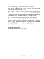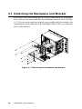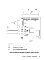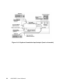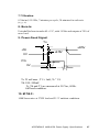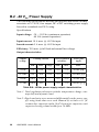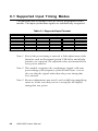
1
AWS-8259
15" TFT LCD workstation with
9 slots
User’s Manual
1
Copyright
This document is copyrighted July, 2002, by Advantech Co., Ltd. All
rights are reserved. Advantech Co., Ltd. reserves the right to make improvements to the products described in this manual at any time. Specifications are thus subject to change without notice.
No part of this manual may be reproduced, copied, translated, or transmit-ted in any form or by any means without the prior written permission
of Advantech Co., Ltd. Information provided in this manual is intended
to be accurate and reliable. However, Advantech Co., Ltd., assumes no
responsibility for its use, nor for any infringements upon the rights of
third parties which may result from its use.
Acknowledgements
AWS-8259T, AWS-8259TP, AWS-8259T-T and AWS-8259TP-T are all
trademarks of Advantech Co., Ltd. IBM and PC are trademarks of International Business Machines Corporation. MS-DOS is a trademark of
Microsoft Corporation. All other brand and product names mentioned
herein are trademarks or registered trademarks of their respective owners.
1st Edition
Printed in Taiwan
2
AWS-8259 User's Manual
July 2002
FCC Class A
This equipment has been tested and found to comply with the limits for a
Class A digital device, pursuant to Part 15 of the FCC Rules. These
limits are designed to provide reasonable protection against harmful interfer-ence when the equipment is operated in a commercial environment. This equipment generates, uses and can radiate radio frequency
energy. If not installed and used in accordance with this user’s manual, it
may cause harmful interference to radio communications. Operation of
this equip-ment in a residential area is likely to cause harmful interference, in which case the user will be required to correct the interference at
his own expense.
3
Packing List
Before you set up the AWS-8259 workstation, make sure that the
following materials have been included with the package, and that this
manual is in good condition. If anything is missing or damaged, contact
your dealer immediately:
• One AWS-8259 industrial workstation with 15" flat panel display
•
-
One accessory box, including:
One power cord
One HMI manual and drivers CD-ROM
Cable to link front PS/2 connector to CPU card
Flat gray cable for 3.5" HDD and slim CD-ROM
Cable to link front VGA connector to CPU card (DB-15, male to male)
Cable to link USB/Ind./Power connector to chassis (male to male)
Eight rubber clamp pads which attached to hold-on clamp
RS-232 cable to link touchscreen to CPU card (only -T models)
• CDR-842-0024
• CDR-8259-24X (optional)
- 24X slim type CD-ROM
- Power cable
- Screw bag with four screws
• USB-3250
- 2 m cable to link front VGA connector to CPU card
- 2 m cable to link front PS/2 connector to CPU card
- 2 m cable to link USB/Ind./Power connector to chassis
- Front floppy cover bracket
If any of these items are missing or damaged, contact your distributor or
sales representative immediately.
4
AWS-8259 User's Manual
Safety Instructions
1. Read these safety instructions carefully.
2. Keep this User’s Manual for later reference.
3. Disconnect this equipment from any AC outlet before cleaning. Use
a damp cloth. Do not use liquid or spray detergents for cleaning.
4. For plug-in equipment, the power outlet socket must be located near
the equipment and must be easily accessible.
5. Keep this equipment away from humidity.
6. Put this equipment on a reliable surface during installation. Dropping it or let-ting it fall may cause damage.
7. The openings on the enclosure are for air convection. Protect the
equipment from overheating. DO NOT COVER THE OPENINGS.
8. Make sure the voltage of the power source is correct before connecting the equipment to the power outlet.
9. Position the power cord so that people cannot step on it. Do not place
anything over the power cord.
10. All cautions and warnings on the equipment should be noted.
11. If the equipment is not used for a long time, disconnect it from the
power source to avoid damage by transient overvoltage.
12. Never pour any liquid into an opening. This may cause fire or electrical shock.
13. Never open the equipment. For safety reasons, the equipment should
be opened only by qualified service personnel.
14. If one of the following situations arises, get the equipment checked
by service personnel:
a. The power cord or plug is damaged.
b. Liquid has penetrated into the equipment.
c. The equipment has been exposed to moisture.
d. The equipment does not work well, or you cannot get it to work
accordingto the user’s manual.
5
e. The equipment has been dropped and damaged.
f. The equipment has obvious signs of breakage.
15. DO NOT LEAVE THIS EQUIPMENT IN AN ENVIRONMENT
WHERE. THE STORAGE TEMPERATURE MAY GO BELOW 20° C (-4° F) OR ABOVE 60° C (140° F). THIS COULD DAMAGE THE EQUIPMENT. THE EQUIPMENT SHOULD BE IN A
CONTROLLED ENVIRONMENT.
The sound pressure level at the operator’s position according to IEC
704-1:1982 is no more than 70dB (A).
DISCLAIMER: This set of instructions is given according to IEC 704-1.
Advan-tech disclaims all responsibility for the accuracy of any statements contained herein.
6
AWS-8259 User's Manual
Wichtige Sicherheishinweise
1. Bitte lesen sie Sich diese Hinweise sorgfältig durch.
2. Heben Sie diese Anleitung für den späteren Gebrauch auf.
3. Vor jedem Reinigen ist das Gerät vom Stromnetz zu trennen. Verwenden Sie Keine Flüssig-oder Aerosolreiniger. Am besten dient ein
angefeuchtetes Tuch zur Reinigung.
4. Die NetzanschluBsteckdose soll nahe dem Gerät angebracht und leicht zugänglich sein.
5. Das Gerät ist vor Feuchtigkeit zu schützen.
6. Bei der Aufstellung des Gerätes ist auf sicheren Stand zu achten. Ein
Kippen oder Fallen könnte Verletzungen hervorrufen.
7. Die Belüftungsöffnungen dienen zur Luftzirkulation die das Gerät
vor überhit-zung schützt. Sorgen Sie dafür, daB diese Öffnungen nicht
abgedeckt werden.
8. Beachten Sie beim. AnschluB an das Stromnetz die AnschluBwerte.
9. Verlegen Sie die NetzanschluBleitung so, daB niemand darüber fallen kann. Es sollte auch nichts auf der Leitung abgestellt werden.
10. Alle Hinweise und Warnungen die sich am Geräten befinden sind zu
beachten.
11. Wird das Gerät über einen längeren Zeitraum nicht benutzt, sollten
Sie es vom Stromnetz trennen. Somit wird im Falle einer Überspannung eine Beschädi-gung vermieden.
12. Durch die Lüftungsöffnungen dürfen niemals Gegenstände oder Flüssigkeiten in das Gerät gelangen. Dies könnte einen Brand bzw. elektrischen Schlag aus-lösen.
13. Öffnen Sie niemals das Gerät. Das Gerät darf aus Gründen der elektrischen Sicherheit nur von authorisiertem Servicepersonal geöffnet
werden.
14. Wenn folgende Situationen auftreten ist das Gerät vom Stromnetz
zu trennen und von einer qualifizierten Servicestelle zu überprüfen:
7
a - Netzkabel oder Netzstecker sind beschädigt.
b - Flüssigkeit ist in das Gerät eingedrungen.
c - Das Gerät war Feuchtigkeit ausgesetzt.
d - Wenn das Gerät nicht der Bedienungsanleitung entsprechend
funktioniert oder Sie mit Hilfe dieser Anleitung keine Verbesserung
erzielen.
e - Das Gerät ist gefallen und/oder das Gehäuse ist beschädigt.
f - Wenn das Gerät deutliche Anzeichen eines Defektes aufweist.
Der arbeitsplatzbezogene Schalldruckpegel nach DIN 45 635 Teil 1000
beträgt 70dB (A) oder weiger.
DISCLAIMER: This set of instructions is given according to IEC704-1.
Advantech disclaims all responsibility for the accuracy of any statements
contained herein.
8
AWS-8259 User's Manual
Contents
Chapter 1
1.1
1.2
1.3
1.4
1.5
1.6
Introduction ............................................... 1
Description ........................................................................................ 2
Specifications .................................................................................... 4
Features ............................................................................................. 6
Dimensions ........................................................................................ 7
Complete Functionality ................................................................... 8
Modular Design Concept ................................................................. 9
Chapter 2
System Setup .......................................... 11
2.1 Integration system setup ................................................................ 12
2.1.1
2.1.2
2.1.3
2.1.4
2.1.5
2.1.6
2.1.7
2.1.8
2.1.9
General ................................................................................. 12
Opening the Rear Panel ..................................................... 13
Adding Cards ....................................................................... 14
Installing Hold-down Clamps ............................................. 15
Installing Optional Disk Drives .......................................... 16
Connecting Cables ............................................................. 20
Connecting External Keyboard and Mouse ...................... 22
Panel Mounting ................................................................... 23
Rack Mounting .................................................................... 24
Chapter 3
Macro Key Programming ........................ 25
3.1
3.2
3.3
3.4
3.5
Introduction .................................................................................... 26
Macro Components ........................................................................ 26
Syntax .............................................................................................. 27
How To Use SFED8259 COM ....................................................... 29
Examples ......................................................................................... 30
Chapter 4
Maintenance ............................................ 33
4.1 Detaching the Backplane and Bracket ......................................... 34
4.2 Power Supply .................................................................................. 35
4.3 Keyboard Translator ..................................................................... 36
9
Appendix A Separate system setup ........................... 39
A.1 Separate system setup ..................................................................... 40
A.1.1 How to separate the AWS-8259 ......................................... 40
A.1.2 Connecting the LCD monitor and control chassis .......... 41
A.1.3 Install the 3.5" floppy in the front panel ............................ 43
A.2 Mounting ......................................................................................... 45
A.2.1
A.2.2
A.2.3
A.2.4
A.2.5
Panel Mounting ................................................................... 45
Rack Mounting .................................................................... 46
Wall Mounting ...................................................................... 46
Desktop Stand ..................................................................... 47
Swing Arm Mounting .......................................................... 48
Appendix B Power Supply Specifications ................. 49
B.1 Voltage Characteristics .................................................................. 50
B.2 -48 VDC Power Supply .................................................................. 58
B.3 24 VDC Power Supply ................................................................... 62
Appendix C OSD Selection ......................................... 65
C.1 Supported Input Timing Modes .................................................... 66
C.2 Keypad Interface ............................................................................ 67
C.3 OSD Function ................................................................................. 68
1 0
AWS-8259 User's Manual
Figures
Figure 1-1:
Figure 1-2:
Figure 1-3:
Dimensions ............................................................................................ 7
Complete functionality ........................................................................ 8
Modular design concept ...................................................................... 9
Figure 2-1:
Figure 2-2:
Figure 2-3:
Figure 2-4:
Figure 2-5:
Figure 2-6:
Figure 2-7:
Figure 2-8:
Figure 2-9:
Figure 2-10:
Figure 2-11:
Figure 2-12:
Opening the rear door ....................................................................... 13
Installing add-on cards ...................................................................... 14
Card Installation Note ....................................................................... 15
Installing Hold-down clamp .............................................................. 16
Installing optional disk drives - overall view ................................... 16
Installing two hard disks & CD-ROM ............................................. 18
Installing floppy ................................................................................. 19
Connecting cables .............................................................................. 21
Connect front keyboard ..................................................................... 22
Connect rear KB ................................................................................ 22
Panel mounting .................................................................................. 23
Rack mounting ................................................................................... 24
Figure 3-1:
Figure 3-2:
The Macro Editor screen .................................................................. 29
Macro examples ................................................................................. 30
Figure 4-1:
Figure 4-2:
Figure 4-3:
Figure 4-4:
Detaching the backplane and bracket .............................................. 34
Installing the power supply ............................................................... 35
Keyboard translator input/output (basic schematic) ...................... 37
Keyboard translator input/output (basic schematic) ...................... 38
Figure A-1:
Figure A-2:
Figure A-3:
Figure A-4:
Figure A-5:
Figure A-6:
Figure A-7:
Figure A-8:
Figure A-9:
Figure A-10:
Detach the LCD panel and controlling chassis ................................ 40
Connecting the control chassis .......................................................... 41
Screw the steel plate .......................................................................... 42
Re-install the floppy ........................................................................... 42
Screw the housing kit ......................................................................... 44
Panel Mounting .................................................................................. 45
Rack Mounting ................................................................................... 46
Wall Mounting ................................................................................... 46
Desktop Stand .................................................................................... 47
Swing Arm Mounting ........................................................................ 48
11
Tables
Table B-1:
Table B-2:
Table B-3:
Table B-4:
Table B-5:
Table B-6:
Table B-7:
Table B-8:
Table B-9:
1 2
Static output characteristics ............................................................. 51
DC output current load range .......................................................... 52
Step load limit .................................................................................... 53
Over voltage protection ..................................................................... 54
Harmonic Limits, Class D ................................................................. 56
-48 VDC power supply output characteristics ................................... 58
-48 VDC power supply DC output wire list ....................................... 61
24 VDC Power Supply Output load range ......................................... 62
24 VDC Power Supply load regulation .............................................. 63
AWS-8259 User's Manual
CHAPTER
1
Introduction
• Description
• Specifications
• Features
• Dimensions
• Complete Functionality
• Modular Design Concept
Chapter 1 AWS-8259 Introduction
1
1.1 Description
The AWS-8259 is an all-new designed, 9-slot, 15" TFT LCD workstation. With a flexible two-piece design, the AWS-8259 is not only considered to be an integrated computing workstation but can be separated and
used as a LCD display and control chassis. This provides a flexible and
cost-saving way for users to meet different kinds of application needs for
industrial computing platforms. The AWS-8259 also provides many powerful features such as an easy-to-maintain, waterproof touch pad; front
access USB port & floppy; vibration protection for two HDDs. Thus, the
AWS-8259 is especially suitable for oil monitoring systems, ship control
centers, machine automation and more.
Two-piece design meets all your applications
Sometimes, users want to save the installing space or keep the LCD
monitor away from the control computer to protect the control data. They
need a LCD monitor and control chassis that can be separated. The
AWS-8259 can do that. The AWS-8259 can be configured two ways,
integrated or separated, to meet the all the requirements of industrial
computing platforms. This provides additional flexibility for users to set
up flexible systems according to their applications.
Easy-to-maintain
The AWS-8259 makes maintenance fast and easily. First, if there are
problems with the LCD display, the two-piece design allows you to
replace it or service it simply and quickly. This helps saves downtime
costs associated with system crashes. Secondly, the AWS-8259 provides
a "hinge" for the rear door. When you open the rear door and want to
maintain the CPU or I/O cards, them hinged rear door makes access
much more convenient. Third, when maintaining floppy, HDD or
CD-ROM, users do not need to take out multiple screws. It only takes
few seconds to replace or service devices. The AWS-8259 provides a
simple and quick way for users to maintain systems, saving much time
and effort.
2
AWS-8259 User's Manual
Easy front panel access
To provide a convenient way for users to access data, the AWS-8259
offers complete I/O ports in the front panel for devices such as a touch
pad; 2 USB ports; a PS/2 port for keyboard; floppy drive, function &
programming keys. This makes it easier to access data from the panel
instead of from the control chassis.
Special design to protect HDD & CD-ROM from vibration
damage up to 1 G
The AWS-8259 also provides a special design for HDD/CD-ROM
vibration protection. This makes the AWS-8259 especially suited for the
easy-to-vibrate environment such as ship controlling center; train or truck
monitoring; machinery and more.
Industrial design meets every harsh environment
In addition, the AWS-8259 also features many powerful functions to
meet the industrial-grade requirements. The front panel is made of Aluminum and being chemical treated by anode. That prevents the panel
from damaging by acid and salt. Besides, it's waterproof and IP65/
NEMA4 compliant. The AWS-8259 also offers the stainless steel chassis. It also protects the chassis. For keeping the system working properly,
the AWS-8259 provides a fan & filter to avoid overheating & dust. In
addition, the AWS-8259 also provides three mounting ways to fit different application: 19" rack, panel or wall mounting.
Chapter 1 AWS-8259 Introduction
3
1.2 Specifications
Type: Integrated or separate LCD panel/ control chassis
LCD Panel
• Display type: 15" SVGA TFT LCD
• Front panel: Aluminum, meets NEMA4/IP65
• LCD display interface: VGA
• Max. Resolution: 1024 x 768
• Maximum Colors: 262 K
• Luminance (cd/m2): 200
• Viewing angle: 120°(H), 100°(V)
• LCD MTBF: 50,000 hours
• Backlight lifetime: 25,000 hours
• Display setting: OSD on front panel
• I/O port: 2 USB ports, floppy drive, 6-pin PS/2 keyboard connector
with dust-protection door
• Touch pad interface: PS/2 mouse
• Indicators: LEDs for Power On/Off and HDD activity
• Membrane keypads: One with 39 operating keys, one with 10
function keys and 10 programmable macro function keys
• Operating temperature: 0 ~50°C
Control Chassis
• Chassis: Stainless steel
• Slot:
1 CPU, 8 ISA (AWS-8259T or AWS-8259T-T series).
1 CPU, 4 ISA, 4 PCI (AWS-8259TP or AWS-8259TP-T series)
• Disk drive housing: Supports one 3.5" FDD, two 3.5" HDD & one
slim CD-ROM (HDD and CD-ROM optional)
4
AWS-8259 User's Manual
• Cooling system: One 86 CFM fan
• Operating temperature: 0° ~ 50° C (32° ~ 122° F)
• Relative humidity: 5 ~ 85% @ 40° C, non-condensing
• Storage temperature: -20° ~ 60° C
• Storage humidity: 5 ~ 95% non-condensing
• Dimensions (W x H x D): 483 x 355 x 235 mm (19" x 14" x 9.3")
• Gross Weight: 22 kg (48.4 lbs)
• CE, FCC, BSMI compliant
Passive Backplane
• PCA-6109P4: 4 PCI, 4 ISA, 1 CPU slot backplane
• PCA-6109: 9 ISA slot backplane
Power Supply
AC input 300 W (standard offer)
• Input: 90 ~ 135 V AC or 180 ~ 265 V AC , switchable
• Output: +5 V @ 30 A; +12 V @ 15 A; +3.3 V @ 24 A
-5 V @ 0.3 A; -12 V @ 0.8 A; +5 V SB @ 2 A
• MTBF: 100,000 hours
• Safety: UL/CSA/TUV
• Input: 90 ~ 135 V AC or 180 ~ 265 V AC , switchable
• Output: +5 V @ 30 A; +12 V @ 15 A; +3.3 V @ 24 A
-5 V @ 0.3 A; -12 V @ 0.8 A; +5 V SB @ 2 A
• MTBF: 100,000 hours
• Safety: UL/CSA/TUV
Chapter 1 AWS-8259 Introduction
5
1.3 Features
• 15", 9-slot TFT LCD workstation, resolution : 1024 x 768
• Two-piece design: integrated or separated LCD panel & control
chassis.
• Built-in touch pad, USB port, floppy on the front panel
• Special design makes maintenance simple and easy- rear door hinge.
• Vibration protection up to 1 G
• IP65/NEMA 4, Aluminum panel and stainless steel chassis.
Note: For AWS-8259 series, we recommend PCA-6180, PCA-6003
series CPU cards.
6
AWS-8259 User's Manual
1.4 Dimensions
Before you rack-mount or panel-mount the AWS-8259, use the following
diagram to verify that the mounting screws correspond with the holes in
your panel/rack.
222.00 [8.74]
181.50 [7.15]
482.60 [19.00]
465.00 [18.31]
332.80 [13.10]
11.00 [0.43]
354.80 [13.97]
53.50 [2.11]
13.00 [0.51]
279.40 [11.00]
13.00 [0.51]
25.00 [0.98]
15.50 [0.61]
445.60 [17.54]
375.60 [14.79]
Cut-out dimensions : 449 mm X 336 mm
Figure 1-1: Dimensions
Chapter 1 AWS-8259 Introduction
7
1.5 Complete Functionality
Aluminum alloy panel meets
Data-entry keypad
15” TFT LCD
Reset switch
HDD indicator (Left)
Power indicator (Right)
OSD
Front access floppy
20 programmable
function/macro keys
Two front access USB ports
Power switch
Water-proof touch pad
Dust protection door
Keyboard connector
Stainless chassis
VGA connector
Power on/off switch
(only for LCD monitor)
Cooling fan with filter
PS/2 Keyboard/mouse port
Rear keyboard
connector
USB/Ind./Power connector
CD-ROM
RS-232 for Touch screen
Industrial
power supply
Figure 1-2: Complete functionality
8
AWS-8259 User's Manual
1.6 Modular Design Concept
The AWS-8259 is designed with a modular concept. The whole system
consists of two major parts: an LCD panel and a control chassis. This
modular concept effectively reduces maintenance. To disassemble the
system, please refer to Chapter 4.
Figure 1-3: Modular design concept
Chapter 1 AWS-8259 Introduction
9
10
AWS-8259 User's Manual
CHAPTER
2
System Setup
• General
• Opening the Rear Panel
• Adding cards
• Installing Hold-down Clamps
• Installing optional drives
• Connecting cables
• Connecting External Keyboard and
Mouse
• Rack/Panel/Wall mounting
Chapter 2 AWS-8259 System Setup
11
2.1 Integration system setup
The WS-8259 offers two ways to meet the requirements of industrial
computing platforms, integrated or separated applications. For integrated application,the AWS-8259 can be used as a complete computing
platform.It supports a 9 ISA/PCI slot,15"TFT LCD workstation. For separated applications,the WS-8259 can be separated into a LCD monitor
and control chassis.
2.1.1
General
The AWS-8259 adopts a standard industrial PCI/ISA backplane. After
installing the CPU card and other accessories, this system is operational.
And the standard front panel layout allows the system to be easily
mounted in a 19-inch rack.
Warning!
12
Do not begin your installation until you are sure there is
no power flowing within the AWS-8259. It must be
switched off and unplugged. Every time you access the
interior of the AWS-8259, you should switch it off and
unplug it.
AWS-8259 User's Manual
2.1.2
Opening the Rear Panel
Unscrew the two knobs in the rear panel and open the back cover
(see Fig. 2-1). The back cover is "hinged" to the chassis. If necessary,
unplug the power cord of the fan to remove the rear door.
Figure 2-1: Opening the rear door
Chapter 2 AWS-8259 System Setup
13
2.1.3
Adding Cards
The PCI passive backplane accepts both PCI-bus and ISA-bus CPU and
I/O cards. We recommend all-in-one cards. They are durable, and save
valuable slot space by bundling a CPU card with hard disk and floppy
disk controllers, as well as serial and parallel ports.
Open the rear door (see Fig. 2-2) and then slowly slide the card in and
carefully press it into the backplane socket. Secure it with a screw to the
side-mounting bar. Connect the wires. Install additional cards as needed.
When you have finished, close the door.
Figure 2-2: Installing add-on cards
Note: When installing or maintaining the unit, do not invert the unit or
place it face down. Handling the unit in that way can cause mechanical
damage to the unit.
14
AWS-8259 User's Manual
Figure 2-3: Card Installation Note
2.1.4
Installing Hold-down Clamps
After installing the cards on the backplane, you may want to affix holddown clamps to secure the cards better.
Take the several round rubber pads and clamps from the accessory box.
Choose a suitable position on the clamp shelf whereby the card can be
firmly secured. Put the round rubber pads in the holes with the clamps.
(see Fig. 2-4). Then insert the clamp and screw it in the chassis.
Warning!
Make sure the round rubber pads on the hold-down clamp
are firmly glued to the clamp. If any metal part of the clamp
contacts any card, it may cause a short circuit.
Chapter 2 AWS-8259 System Setup
15
Figure 2-4: Installing Hold-down clamp
2.1.5
Installing Optional Disk Drives
The AWS-8259 provides space for the drives (one 3.5" floppy disk
drive, two 3.5" hard disk drives and one slim CD-ROM drive)
underneath the case. A front-facing floppy drive has already been
installed. You can access it from the FDD dust-resistant door panel.
A slim CD-ROM and HDD unit can be installed in the bottom of the
chassis.
Figure 2-5: Installing optional disk drives - overall view
16
AWS-8259 User's Manual
Figure 2-6: Installing two hard disks & CD-ROM
Chapter 2 AWS-8259 System Setup
17
Figure 2-7: Installing floppy
18
AWS-8259 User's Manual
2.1.6
Connecting Cables
After inserting the CPU card into the chassis, connect the FDD, CDROM and HDD cables to the CPU card. In addition to the storage devices, four other cables need to be connected: the PS/2 touch pad cable,
VGA cable, USB/Ind./Power cable and RS-232 cable for the touch screen.
The PS/2 mouse cable is used to connect the touch pad signal output
from the front panel to the CPU card, as shown below. There is a keyboard control board in the system that integrates the keyboard signals. If
your workstation is equipped with a touch screen, connect the touch screen
controller and CPU card through the RS-232 cable as shown below.
Connect USB/Indicator/Power cable to chassis
Chapter 2 AWS-8259 System Setup
19
Connect PS/2 Touchpad/Keyboard cable to CPU card
Connect VGA cable to CPU card
Figure 2-8: Connecting cables
20
AWS-8259 User's Manual
2.1.7
Connecting External Keyboard and Mouse
You can connect an external keyboard to the workstation. The connection to the keyboard is the PS/2 connector on the front panel, under the
dust-protection door. Please note that you CANNOT connect a mouse to
the PS/2 connector on the front panel.
There are two additional keyboard connectors on the back of the chassis
as shown in figure 2-10. You cannot connect two keyboards to these two
connectors on the back at the same time. You could however, connect a
keyboard to the front panel PS/2 connector and another to one to the
keyboard connectors at the back of the chassis at the same time.
Figure 2-9: Connect front keyboard
Figure 2-10: Connect rear KB
Chapter 2 AWS-8259 System Setup
21
2.1.8
Panel Mounting
The AWS-8259 can be installed on a shelf or table, or mounted within a
panel. Dimensions for the case, the mounting flanges, and the mounting
bolts are shown in Fig. 2-11.
Once you have added your cards, drives, and other equipment, you can
switch on the AWS-8259 to check if it operates properly. Then the case
can be set within your panel aperture so that your screw holes line up
with the mounting bolts on the flanges of the AWS-8259. Finally, secure
the bolts to the panel.
Figure 2-11: Panel mounting
22
AWS-8259 User's Manual
2.1.9 Rack Mounting
The AWS-8259 can also be mounted in a 19" rack. Make sure that all
additional equipment has been installed correctly. Also, make sure that
all cabling (such as the monitor signal cable, the keyboard cable and the
monitor power cable) have been reattached. Fit the rack into the case by
using screws on both sides of the case.
Figure 2-12: Rack mounting
Chapter 2 AWS-8259 System Setup
23
24
AWS-8259 User's Manual
CHAPTER
3
Macro Key Programming
• Introduction
• Macro Components
• Syntax
• How to Use SFED8259 COM
• Examples
Chapter 3 AWS-8259 Macro Key Programming
25
3.1 Introduction
Our workstations are equipped with programmable function keys (macro keys) that greatly enhance the operator interface. Macros, far more
powerful than batch files, automate the most commonly used input sequences. They extended their functional reach to within application programs.
3.2 Macro Components
The following article explains how to use and program the function keys.
The complete macro function consists of the following elements:
Macro keys
Ten programmable macro keys that are located under the monitor screen
of your workstation.
Macro EEPROM
Holds the key sequences that are activated when the corresponding macro key is pushed.
Macro programming utility
Locate the program SFED8259 COM in the Function Key Utility diskette for function key programming. The SFED software provides an
edit function to produce an ASCII file that contains keystroke sequences
for every macro key. After you have finished editing the file, the program will ask you whether you want to save the macro script and/or
transmit it to the EEPROM. Macros consist of keystroke sequences to
automate the most common procedures in your application. The way
they function is much like batch files (.BAT) under DOS, but there are
some differences. In a Macro you have to specify the ENTER key explicitly. Macros give you the possibility to enter key sequences in an
application that was executed by the macro itself.
26
AWS-8259 User's Manual
3.3 Syntax
Macro definitions consist of ASCII characters or character codes for
special characters such as ALT, ENTER, SHIFT, F1, SF2, and so on.
These codes are predefined, and SFED8259.COM will display them on
the screen for you. They are easily recognizable, appearing between the
square brackets ‘[‘ and ‘]’.
For example:
ALT represents [26]
ENTER represents [33]
In your macro script, you can enter ordinary text (ASCII characters) or
the code(s) of the required special character(s).
For example:
CD\TOOLKIT[33] means CD\TOOLKIT [ENTER]
For combination keystrokes (ALT/SHIFT/CTRL + another key)
enter the codes of the special characters, followed by
[90] (RELEASE).
Chapter 3 AWS-8259 Macro Key Programming
27
For example:
ALT-F1 represents [26][44][90]
CRTL-C represents [28]C[90]
SHIFT-B represents [27]B[90]
Please refer to the following examples:
ALT-X represents [26]X[90] or [26]x[90].
ALT-F1 represents [26][44][90]
SHIFT-X represents [27]X[90]
SHIFT-F1 represents [27][44][90]
CTRL-X represents [28]X[90]
CTRL-F represents [28][44][90]
CTRL-ALT-DEL represents [28][26][41][90] (reboot)
CTRL-ALT-A represents [28][26]A[90]
CTRL-SHIFT-1 represents [28][27]1[90]
Another useful function is the DELAY instruction. You can instruct the
macro program to wait before executing the next keystroke.
SFED8259.COM displays the codes that you can use for various delays.
For example:
[86] - Wait for 10 seconds before executing next keystroke
[88] - Wait for 1 minute before executing next keystroke.
[26]A[90][86][26]B[90] means ALT-A, wait 10 seconds, ALT-B
28
AWS-8259 User's Manual
3.4 How To Use SFED8259 COM
First, boot your system under pure DOS mode (not DOS shell in windows) and copy all the files to your hard disk and/or make a backup disk.
Then start the macro editor, you will have to specify either an existing
macro script file or a new macro script file. Here we will create a new
file by typing SFED8259 NEWKEY.TXT
[ENTER].
Note: SFED8259.COM could only work properly under pure DOS mode.
The following screen will appear:
Advantech Workstation Special Function Key Edit Program
Rev. 11/16/1995
Table of Control Codes :
Example : SF5 =CD\WINDOWS[33]WIN[33]
TAB [24]
ALT [26]
SHIFT [27]
CTRL [28]
ENTER[33]
PRTSC[7E]
PAUSE[7F]
[ [30]
HOME [3C]
END [3D]
↑ [38]
PGUP [3E]
F1 [44]
F5 [48]
PGDN [3F]
INS [40]
F9 [4C]
DEL [41]
RELEASE [90]
SF1 to SF10 = [70] to [79]
] [31]
↓ [39]
F2 [45]
F6 [49]
F10 [4D]
BS [35]
← [3A]
F3 [46]
F7 [4A]
F11 [4E]
ESC[36]
→ [3B]
F4 [47]
F8 [4B]
F12 [4F]
Key delay Mode :
0.1 Sec [80]
5 Sec [85]
SF1 =
SF2 =
SF3 =
SF4 =
SF5 =
SF6 =
SF7 =
SF8 =
SF9 =
SF10 =
0.5 Sec [81]
10 Sec [86]
1 Sec [82]
30 Sec [87]
2 Sec [83]
1 Min [88]
3 Sec [84]
1 Hour [89]
CD\TOOL[33]SFED825 EXAMPLE.TXT[33]
COPY C:\CONFIG.EMM C:\CONFIG.SYS[33]Y[33][85][79]
C:\WP51\WP[33][86][27][4D][90]REPORT.WP5[33]
[28][26][41][90]
Save(Y/N)?
Transmit(Y/N)?
KBT ID:AD111695
ESC:Quit/Save/Transmit
Figure 3-1: The Macro Editor screen
Chapter 3 AWS-8259 Macro Key Programming
29
When you have finished editing, press the ESC key. At the bottom line of
the screen you will be prompted to choose if you want to save the file
and/or if you want to transmit it to the EEPROM.
After confirmation with the ENTER key, the tasks are carried out and
you return to DOS.
3.5 Examples
We will explain all macro functions that you can find in the EX8259.TXT
macro script file. After typing SFED8259 EX8259.TXT
[ENTER], the following editor screen will appear:
TAB [24]
ALT [26]
SHIFT [27]
CTRL [28]
ENTER[33]
PRTSC[7E]
PAUSE[7F]
HOME [3C]
[ [30]
END [3D]
↑ [38]
F1 [44]
PGUP [3E]
F5 [48]
PGDN [3F]
F9 [4C]
INS [40]
RELEASE [90]
DEL [41]
SF1 to SF10 = [70] to [79]
] [31]
↓ [39]
F2 [45]
F6 [49]
F10 [4D]
Key delay Mode :
0.1 Sec [80]
5 Sec [85]
0.5 Sec [81]
10 Sec [86]
1 Sec [82]
30 Sec [87]
SF1 =
SF2 =
SF3 =
SF4 =
SF5 =
SF6 =
SF7 =
SF8 =
SF9 =
SF10 =
Figure 3-2: Macro examples
30
AWS-8259 User's Manual
2 Sec [83]
1 Min [88]
SF1 = CD\TOOL[33] SFED8259 EXAMPLE.TXT[33]
This macro changes to the TOOL directory, then starts up
SFED8259.COM with EXAMPLE.TXT.
SF2 = COPY C:\CONFIG.EMM C:\CONFlG.SYS[33]Y[33][85][79]
The configuration information is changed by copying CONFIG.EMM to
CONFIG.SYS. After a delay of 5 seconds, [85], the macro, invokes macro
function key SF10, [79], which was defined to reset the system.
SF4 = C:\WP51\WP[33][86][27][4D][90]REPORT.WP5[33]
This example shows that after a macro executes, it is able to direct the
program to accomplish several tasks. WordPerfect is started.
After a delay of 10 seconds (time to load the program), the com-mand
Shift-F10, [27][4D], is issued to import a text file. The name of the text
file (REPORT.WP5) is inserted and finally ENTER, [33], causes the text
file to be loaded and appear on the screen.
SF10 = [28][26][41][90]
Restarts the computer (CTRL-ALT-DEL).
Chapter 3 AWS-8259 Macro Key Programming
31
32
AWS-8259 User's Manual
CHAPTER
4
Maintenance
• Detaching the Backplane and Bracket
• Power Supply
• Keyboard Translator
Chapter 4 AWS-8259 Maintenance
33
4.1 Detaching the Backplane and Bracket
First remove the card and detach all cables connected to the backplane.
Next, unscrew all screws and take the backplane out of its case. (See Fig.
4-1.) If you want to repair or upgrade your peripherals (for example, the
membrane keypad controller or the backlight of the LCD), you must first
pull out the bracket.
Figure 4-1: Detaching the backplane and bracket
34
AWS-8259 User's Manual
4.2 Power Supply
When undertaking maintenance of the power supply, first shut off all
power input. Remove the rear panel. Unscrew the four screws under the
power supply. The power supply and its bracket can now be detached
from the case. Detach all power connectors linked to the accessory drives
and other components. For the AWS-8259, pull out the connectors on
the front switch. Then remove the power supply kit from the system (see
Fig. 4-2). For the AWS-8259, disassemble the unit as far as the front
panel. Then disconnect the switch connector and take out the power supply.
Warning: Shut off all power to the AWS-8259 before you commence repairing the power supply. Switch off the power and unplug the unit.
Figure 4-2: Installing the power supply
Chapter 4 AWS-8259 Maintenance
35
4.3 Keyboard Translator
The keyboard translator is an interface that switches the signal from the
membrane keypad to the standard AT keyboard. There are six connectors on the board. On top of the board, there are two connectors linking
two flat cables to the membrane keypad (as shown in Fig. 4-3). On the
side of the board, there are four connectors.
For connection details, refer to Fig. 4-4.
When servicing the keyboard translator:
1. Switch off the power, and detach the main power cord.
2. Disassemble the AWS-8259. The translator will be located on the left
side of the front panel.
3. Remove the keypad connector protective bracket.
4. Carefully detach all cables connected to the keyboard translator. (See
Fig. 4-3.)
5. Unscrew the four screws on the corners, pull out the keyboard translator, and replace it.
36
AWS-8259 User's Manual
(A), (B)
Input from operational keypad
(C)
Input from functional keypad
(D)
Output to CPU card
(E)
Input from external keyboard
Figure 4-3: Keyboard translator input/output (basic schematic)
Chapter 4 AWS-8259 Maintenance
37
Figure 4-4: Keyboard translator input/output (basic schematic)
38
AWS-8259 User's Manual
APPENDIX
A
Separate system setup
• How to separate the AWS-8259
• Connecting the LCD monitor and control chassis
• Install the 3.5" floppy in the front panel
• Panel/wall/Rack/Desktop/Swim Arm Mounting
APPENDIX A AWS-8259 Separate system setup
39
A.1 Separate system setup
A.1.1 How to separate the AWS-8259
The AWS-8259 can be separated into two products, the LCD panel and
control chassis. If you want to separate it, detach the LCD panel from the
chassis by unscrewing four screws and the 4 clip holes.
Figure A-1: Detach the LCD panel and controlling chassis
40
AWS-8259 User's Manual
A.1.2 Connecting the LCD monitor and control chassis
Before you connect LCD monitor, there are four connections between
the LCD monitor and the AWS-8259 chassis: These connectors are the
VGA, Keyboard, USB/Power/Indicator and optional RS-232 for touch
screen. Because the AWS-8259 integrates the power, indicator signal,
and USB into one cable, users do not need to connect another power
cord. In addition, please follow the steps.
Note: The max. distance between LCD monitor and chassis is 2 meter.
VGA cable
PS/2 cable
USB/Indicator/
Power cable
Figure A-2: Connecting the control chassis
APPENDIX A AWS-8259 Separate system setup
41
Step 1: Purchase the USB-3250, which includes three cables.
Step 2: Screw in the steel plate, which is in the accessory package of the
USB-3250.
Figure A-3: Screw the steel plate
Step 3: Re-install the floppy
Figure A-4: Re-install the floppy
42
AWS-8259 User's Manual
Step 4: Connect the 2 meter VGA, keyboard, USB / power / Indicator
cable to the chassis
Step 5: Complete the installation
A.1.3 Install the 3.5" floppy in the front panel
If you want to access data via floppy in the front panel, the AWS-8259
also provides a floppy housing kit. Please follow the steps.
Step 1: Purchase the FDD-3250, which includes the housing kit and 3.5
1.44MB floppy.
Step 2: Screw the housing kit into the panel
APPENDIX A AWS-8259 Separate system setup
43
Figure A-5: Screw the housing kit
44
AWS-8259 User's Manual
A.2
Mounting
A.2.1 Panel Mounting
A cutout needs be made to accommodate panel mounting. The panelmount brackets are included in the accessory box. Slide the unit backwards into the panel opening. Attach the mounting brackets by inserting
the screws into the keyhole slots on the flat panel monitor cover. Use the
screws to secure the brackets to the cover. Tighten to secure the front
panel monitor against the back panel.
Figure A-6: Panel Mounting
APPENDIX A AWS-8259 Separate system setup
45
A.2.2 Rack Mounting
The LCD panel can be directly mounted in a standard 19" rack. Just
mount the panel on the rack and secure with four screws.
Figure A-7: Rack Mounting
A.2.3 Wall Mounting
First, mount the wall-mounting bracket to the wall, then mount the LCD
panel onto the bracket using the three provided screws. Finally, secure
the panel to the mounting plate with the locking plate.
Figure A-8: Wall Mounting
46
AWS-8259 User's Manual
A.2.4 Desktop Stand
Mount the desktop-mounting bracket to the back of LCD panel with two
screws as the following drawing shows.
Figure A-9: Desktop Stand
APPENDIX A AWS-8259 Separate system setup
47
A.2.5 Swing Arm Mounting
75
100
There are two sets of Swing-ARM mounting holes, 75 mm and 100 mm
diameter, on the back chassis. You can Mount the LCD panel on the
Swing-ARM through the mounting holes and secure with four screws.
Figure A-10: Swing Arm Mounting
48
AWS-8259 User's Manual
APPENDIX
B
Power Supply Specifications
• 300 watt Power Supply
• -48 VDC Power Supply
• 24 VDC Power Supply
APPENDIX B AWS-8259 Power Supply Specifications
49
B.1 Voltage Characteristics
1. Input Characteristics:
1.1 Input Voltage Range: 90Vac to 135Vac /180Vac to 265Vac
1.2 Normal Voltage Range: 115Vac/230Vac.
1.3 Input Frequency Range: 47 Hz to 63 Hz.
1.4 Max. input AC current 9 A max. @ 115Vac,
4.5 A max. @ 230Vac, max. load.
1.5 Inrush Current: No damage shall occur to the power supply and the fuse
shall not open or exceed its spec.
1.6 Efficiency: 65% min. at 115Vac input max. load.
1.7 5Vsb Standby Efficiency: The power supply shall draw less than 5W of true
input power at 230Vac when in the standby mode and the 5Vsb load is
0.4A.
50
AWS-8259 User's Manual
2. Output Characteristics:
2.1 Static Output Characteristics:
Output Voltage
Load Range
Surge
15 sec.
Regulation
Ripple
Vp- p max.
Min.
Max.
+5V
1A
30A
-
+5%
- 5%
50mV
+12V
0.5A
15A
18A
+5%
- 5%
120mV
- 12V
0A
0.8A
-
+10% - 10%
120mV
- 5V
0A
0.3A
-
+5%
- 5%
100mV
+5VSBV
0A
2A
-
+5%
- 5%
50mV
+3.3V
0.3A
24A
-
+5%
- 5%
50mV
Table B-1: Static output characteristics
Note:
1.) The total output power shall not exceed 300W. The max.
Isurge duration is 10 seconds and the +12V tolerance is
±10% during surge conditions.
2.) The -12V and +5V max. total combined current shall not
exceed 0.8A.
3.) Max. current slew rate shall not exceed 1.0A/ µ S.
4.) The max. conditions power rating of supply is 300W at
25°C.Derate 1W /°Cfrom 50°C to 25°C to yield a max.
continuous power rating of 275W at 50°C.
5.) For output 275W
+3.3V and +5V total O/P power can not exceed 160W.
+3.3V, +5V and +12V total O/P power can not exceed 260W.
6.) For output 300W.
+3.3V and +5V total O/P power can not exceed 180W.
+3.3V, +5V and +2V total O/P power can not exceed 290W.
Table A-1: Static output characteristics
APPENDIX B AWS-8259 Power Supply Specifications
51
2.2 DC Output Current:
12V Load
24W
50W
80W
100W
150W
180W
12V
3.3V
5V
3.3V/5V Max.
Min.
0.5A
0.3A
1A
100W
Max.
2A
7A
15A
Min.
2A
0.3A
1A
Max
4.16A
28A
17.52A
Min.
2A
0.3A
1A
Max.
6.66A
28A
17.52A
Min.
2A
0.3A
1.5A
Max.
8.33A
28A
17.52A
Min.
0.5A
0.3A
2A
Max.
12.5A
28A
9.52A
Min.
0.5A
10A
8A
Max.
15A
18A
10A
180W
180W
180W
140W
110W
Table B-2: DC output current load range
Note:
1.) Noise Test: Noise bandwidth is from 10Hz to 20 MHz.
2.) Add 0.47 µF ceramic capacitor /10 µF tantalum capacitor at
output connector terminals for ripple & noise measurements.
3.) Main O/P shall be enabled by pulled "remote" pin to TTL low
level, and disabled by pulled "remote" pin to TTL high level.
2.3 Dynamic Output Characteristics:
2.3.1 Rise Time: +5V O/P voltage rise from 10% of normal to
within regulation should be less than 25 mS.
2.3.2 Turn-on Delay Time: 1S max. at any condition. AC input
with respect to +5V.
2.3.3 Hold Up Time: 17mS min. for +5V output at 115Vac, AC
zero cross 60Hz, max. load.
2.3.4 Overshoot: Any overshoot at turn on or turn off shall be
less than 10% of the normal value.
52
AWS-8259 User's Manual
2.4 Transient Response (Step Load)
M in.
4.75V 10.8V 3.135V 4.75V
Nom.
+5V
+12V +3.3V
+5Vsb
M ax. 5.25V 13.2V 3.465V 5.25V
Output
Decoupling Caps
Load Change
Step Load
+5V
15000UF
1.0A to 7A and back
0.2A/us
+12V
4000UF
0.5A to 3.5A and back
0.2A/us
+3.3V
5000UF
0.3A to 5.9A and back
0.2A/us
+5Vsb
5000UF
0A to 0.4A and back
0.2A/us
Table B-3: Step load limit
The following transient loads are to be applied to the output. The frequency range of the transient loads described shall be from 1 Hz to 2
KHz. The waveform shall be a square wave with the slope of the rise and
fall at 0.2A/microsecond.
The output voltages shall not exceed regulation limits as defined in Table 3 under the following condition:
Step load changes of up to 20% of full load including steps increasing
from minimum or decreasing from full load, while the other loads remain constant within the rating as in Table 1. In addition, the +12V output shall remain within ±10% tolerance limits and the remaining outputs
shall not exceed regulation limits as defined in Table 3 under the following condition:
Step load change of up to 2A on the +12V output including increasing
from minimum or decreasing from full load, while the other loads remain constant within the ratings as in Table 1. The audible noise level of
the power supply shall not increase during transient loading.
APPENDIX B AWS-8259 Power Supply Specifications
53
3. Protections:
3.1 Over Voltage Protection:
O.V.P
O.V.P. Limit
+3.3V
4.5V
+5V
7V
+12V
15.6V
Table B-4: Over voltage protection
3.2 Short Circuit Protection:
The power supply shall shut down and latch off for shorting +5V, +12V,
-12V, -5V or +3.3V rails to COM and shorting +5Vsb, P/S can latch
down or automatically recovery when the fault condition is removed.
3.3 No Load Operation: No damage or hazardous condition
will occur.
3.4 Cooling and Acoustics:
The power supply shall contain a thermal sensing circuit capable of
varying fan speed. The power supply shall have at T =25 and +5V@1A,
+3.3V@3A, +12V@1A load:
1.) A min. voltage of 6.0V ± 0.5V.
2.) A max. noise level of 30dBA between 0 and 4KHz measured 39.4
inches from the intake side of the fan in free air.
The power supply shall have at T =50°C and max. rated load:
1.) A min.voltage of 12V ± 0.5V.
2.) A max. noise level of 45dBA between 0 and 4KHz measured 39.4
inches from the intake side of the fan in free air.
The fan shall be a Ball Bearing DC brushless tubeaxial fan rated to
operate between a range of 6 to 12V.
54
AWS-8259 User's Manual
4. Dielectric Withstand Voltage:
4.1 Hi Pot Test:
Primary to secondary 2150Vdc 1sec.
Primary to F.G 2150Vdc 1sec.
Trip Current Sensitivity : 600 µ A max. 10mA (AC)
Breakdown Arc Detection: 10 µ S max.
4.2 Insulation Resistance: Primary to safety ground: 500Vdc,
5 M ..... min.
4.3 Leakage Current: Measured at 120 Vac and 460uA max.
5. Conducted EMI:
The power supply shall comply with CISPR 22, Class B for both
conducted and radiated emissions with a 4 dB margin at system level test
only. .
6. Product Safety:
This power supply is designed to meet the following specs.
1.) UL 1950 3rd.
2.) CSA C22.2 No. 234-1990,1st Edition.
3.) EN60 950 and IEC 950 2nd Edition (1993)
including Amendments 1, 2, 3 and 4.
4.) TUV EN60 950: 1993+A1+A2+A3+A4.
5.) NORDIC Certificate EMKO-TSE (74-sec)
207/94.
6.) CB Certificate
6.1 Input Line Current Harmonic Content
The power supply shall meet the requirements of EN61000-3-2 Class D
and the Guidelines for the Suppression of Harmonics in Appliances and
General Use EDC output current load range equipment Class D for harmonic line current content at full rated power.
See Table 1 for the harmonic limits.
APPENDIX B AWS-8259 Power Supply Specifications
55
Table B-5: Harmonic Limits, Class D
Harmonic
Order N
Maximum permissible
harmonic current per watt
mA/W
Maximum permissible
Harmonic current
Amps
3
3.4
2.30
5
1.9
1.14
7
1.0
0.77
9
0.5
0.4
11
0.35
0.33
13
0.30
0.21
3.85/n
0.15X(15/n)
15<n<39
PFC: Apply Table 12 limits as shown for 230V operation and multiply
limits by 230/100 for 100V operation for world-wide requirements in
both EU and Japan, respectively.
non-PFC Not applicable, no harmonic reduction is required.
7. Environment:
7.1 Operating Temperature:+10°C to 50°C .
7.2 Operating Relative Humidity: 5% to 85%.
7.3 Storage Temperature: -40°C to + 70°C .
7.4 Storage Relative Humidity: 5% to 95%.
7.5 Altitude:
Operate properly at any altitude between 0 to 10,000 feet.
storage: 50,000 feet.
7.6 Mechanical Shock:
The power supply shall not be damaged during a shock of 40G half sine
wave, 11mS, non-operation.
56
AWS-8259 User's Manual
7.7 Vibration:
0.38m/m,5-55-5Hz, 7 minutes per cycle, 30 minutes for each axis
(x, y, z).
8. Burn-In:
Unit shall be burn in under 45 ± 5°C, with 115Vac and outputs at 70% of
max. load.
9. Power-Good Signal:
Ts
+4.75V
+5V
+4.75V
0V
PG
Td
0V
Tr
T1
Tr: 25 mS max , T1 ≥ 1mS, Ts ≤ 1S
Td: 100~500mS
Tr, Td and T1 are measured at 90 Vac, 60Hz.
full load condition.
10. M.T.B.F.:
100K hours min. at 275W load and 25 °C ambient conditions.
APPENDIX B AWS-8259 Power Supply Specifications
57
B.2 -48 VDC Power Supply
The following specifications describe the physical and electri-cal characteristics of a 310 W, four output, DC to DC switching power supply
housed in a standard size PS/2 casing.
Specifications
Input voltage: -38 ~ -58 Vdc (continuous operation)
-48 Vdc (normal operation)
Input current: 10 A max. @ -48 Vdc input
Inrush current: 5 A max. @ -48 Vdc input
Efficiency: 70% min. @ full load and normal line voltage
Output characteristics:
Output
voltage
Loading current
Total regulation
tolerance
Noise plus
ripple
Min.
Max.
Surge
Max.
Min.
Max.
+5Vdc
2A
25A
30A
+3%
- 3%
50 mV p- p
+12Vdc
0A
10A
12A
+3%
- 3%
120 mV p- p
+5Vdc
0.0A
1.0A
-
+5%
- 5%
50 mV p- p
- 12Vdc
0.0A
5A
-
+3%
- 3%
120 mV p- - p
Table B-6: -48Vdc power supply output characteristics
Note 1: Total regulation tolerance includes temperature change, warmup drift and dynamic load.
Note 2: Ripple and noise were measured differentially at the power supply using loads that were each shunted by at least a 0.1 µF
ceramic disc capacitor and a 10 µF electrolytic capacitor, each
capacitor having a band width up to 20 MHz.
58
AWS-8259 User's Manual
Overshoot (resistive load):
Any output overshoot when the power is turned on does not exceed 10%
of the nominal output voltage.
Output power: Maximum continuous: 310 W
Power good and power fail signals (optional):
When the power is turned on, the power good signal will acti-vate 100 to
500 ms after all output DC voltages are operating within their respective
regulation limits. The power fail signal will activate at least 1 ms before
the +5 V output voltage falls below its regulation limit.
Short circuit protection:
A short circuit placed on any output to ground is shut down. When the
short circuit conditions have ceased to exist, power will then be recycled
to restart the power supply.
Over-current protection:
The power supply will shut down all the DC outputs when any output is
overloaded beyond its current limit or beyond its nominal line voltage
limit. When the over-current conditions have ceased to exist, power will
then be recycled to restart the power supply.
Current limit ranges: 5 V: 32 ~ 45 A
12 V: 13 ~ 20 A
-12 V: 6 ~ 12 A
-5 V: 1.5 ~ 3 A
Over-voltage protection:
The power supply will shut down all the DC outputs when any output
maximum voltage limit is exceeded. When the over-voltage conditions
have ceased to exist, power will then be recycled to restart the power
supply.
APPENDIX B AWS-8259 Power Supply Specifications
59
Voltage limit ranges: 5 V: 6.25 ±0.75 V
12 V: 14 ±1 V
-5 V: -6.25 ±0.75 V
-12 V: -14 ±1 V
Reset time: When the power supply has automatically shut down, and
the short circuit, over-current and/or over-voltage conditions have ceased
to exist, power will be automatically recycled to restart the power supply
within 3 seconds of such return to normal conditions.
No load start: When the power supply is switched on but with no load
connected, the power supply does not get damaged, and it is still completely safe for users.
Transient response: Dynamic load change: ±50% of maxi-mum
rating load Recovery time: 500 ms max.
Reliability Mean time between failures (MTBF): 100,000
hours minimum
Environmental specifications
Operating temperature: 0 ~ 50° C
Storage temperature: -40 ~ 60° C
Operating and storage humidity: 10 ~ 95% RH
Operating altitude: sea level ~ 15,000 ft
Storage altitude: sea level ~ 50,000 ft
International standards compliance
Safety: UL 1950
CSA 22.2 No. 234
TUV EN 60950
EMI: FCC Part 15 Subpart J Class B
60
AWS-8259 User's Manual
DC output wire list
All DC output cables use UL 1007 type wires.
Table B-7: -48 Vdc power supply DC output wire list
Connector Output Color
P 8- 1
PG
Wire
Length
#AWG (mm)
Orange 18
P 8- 2
+5V
Red
18
P 8- 3
+12V
Yellow
18
P 8- 4
- 12V
Blue
18
P 8- 5
CO M
Black
18
P 8- 6
CO M
Black
18
P 9- 1
CO M
Black
18
P 9- 2
CO M
Black
18
P 9- 3
- 5V
White
18
P 9- 4
+5V
Red
18
P 9- 5
+5V
Red
18
P 9- 6
+5V
Red
18
PE- 1
+12V
Yellow
18
PE- 2
CO M
Black
18
PE- 3
CO M
Black
18
PE- 4
+5V
Red
18
PF- 1
+5V
Red
20
PF- 2
CO M
Black
20
PF- 3
CO M
Black
20
PF- 4
+12V
Yellow
20
PA- 1
+12V
Yellow
18
PA- 2
CO M
Black
18
PA- 3
CO M
Black
18
PA- 4
+5V
Red
18
PB- 1
+12V
Yellow
18
PB- 2
CO M
Black
18
PB- 3
CO M
Black
18
PB- 4
+5V
Red
18
Housing
Terminal
300
BURNDY GTC BURNDY DCK
+30/- 10 6P- 1 or
18- 2TR9 or
equivalent
equivalent
300
BURNDY GTC BURNDY DCK
+30/- 10 6P- 1 or
18- 2TR9 or
equivalent
equivalent
300
AMP 480424- 0 AMP61314 or
+30/- 10 or equivalent
equivalent
150
AMP 171822- 4 AMP 170262- 1
+30/- 10 or equivalent
or equivalent
300
AMP 480424- 0 AMP 61314 or
+30/- 10 or equivalent
equivalent
300
AMP 480424- 0 AMP 61314 or
+30/- 10 or equivalent
equivalent
APPENDIX B AWS-8259 Power Supply Specifications
61
B.3 24 VDC Power Supply
This is a DC to DC switching mode power supply with a 24 VDC input.
Specifications
Input voltage: +19 ~ +32 V DC (normal operation)
Input current: 16 A max. @ +24 V DC input
Inrush current: 10 A max. @ +24 V DC input
Output load range:
Table B-8: 24Vdc Power Supply Output load range
Output Output
No. Load
1
+5V
Min.
load
1.0A
Rated
load
25A
Peak
load
30A
Voltage
accuracy
4.90~5.10 V
11.28~12.72 V
2
+12V
0A
10A
12A
3
-12V
0A
1A
2A
-11.40~-12.60 V
4
-5V
0A
1A
2A
-4.75~5.25 V
At the factory, the +5 V output was set between 5.00 and 5.10 V, while
other outputs were simultaneously set at 60% of their respective rated
loads.
The -5 V and -12 V outputs can be used at their respective rated loads.
The +5 V output should carry a load of at least 4 A.
Output power:
Total DC continuous power does not exceed 250 W. Each output should
be able to operate continuously under its maximumload.
Ripple and noise:
Peak to peak ripple and noise for each output is less than 1% of each
output’s respective voltage. Measurements were per-formed with a 15
MHz bandwidth limited oscilloscope, and each output was terminated
with a 0.47 mF capacitor.
62
AWS-8259 User's Manual
Line regulation:
The output line regulation for each output is less than ±1%, when measured at each output’s respective rated load and under ±10% changing
input voltage conditions.
Load regulation:
The values for each of the following output numbers were obtained by
changing each output load ±40% from the 60% rated load, whilst simultaneously keeping all other outputs at 60% of their respective rated loads.
Table B-9: 24Vdc Power Supply load regulation
Output No.
1
Load regulation
±4%
2
±5%
3
±3%
4
±3%
Power good signal:
When the power is turned on, the power good signal will acti-vate 100 to
500 ms after all output DC voltages are operating within their respective
regulation limits.
Power fail signal:
This will activate at least 0.5 ms before any of the output voltages fall
below their respective regulation limits.
APPENDIX B AWS-8259 Power Supply Specifications
63
General features
Efficiency:
65% typical when measured at nominal input and rated load.
Input protection:
Protection against wrong polarity if the +24 V input voltage is mistakenly reversed.
Output protection:
If for some reason the power supply fails to control itself, the built-in
over-voltage protection circuit will shut down the outputs to prevent damage to external circuits. The trip point of the crowbar circuit is approximately 5.7 ~ 7.0 V.
Environmental specifications
Operating temperature: 0-45°C
Storage temperature: -40-75°C
International standards compliance
Safety: UL 1950
CSA 234
TüV EN 60950
64
AWS-8259 User's Manual
APPENDIX
C
OSD Selection
• Keypad Interface
• OSD Function
C.1 Supported Input Timing Modes
The nineteen kinds of timings below are already programmed in this
module. The input synchronous signals are automatically recognized.
Table A.1: Supported Input Formats
Vertical Frequencies
Resolution
56 Hz
60 Hz
Yes
Yes
Yes
Yes
Yes
Yes
Yes
640 x 480
800 x 600
1024 x 768
Yes
70 Hz
Yes
72 Hz
75 Hz
Yes
Note 1: Even if the preset timing is entered, a little adjust-ment of the
functions such as Horizontal period, CLK-delay and display
position, are required. The adjusted values are memorized in
every preset num-ber.
Note 2: This module recognizes the synchronous signals with near
preset timing of the frequency of the HS and Vsync, even in
the case that the signals other than the preset timing that
were entered.
Note 3: Because adjustments may not fit, such as differing magnifying
ratios or, in the case that you use it except for the display
timing that was preset.
66
AWS-8259 User's Manual
C.2 Keypad Interface
The keypad interface provides driver for a dual color LED for status
indication.
AUTO
Press this button to execute auto adjustment process.
SEL
Presses to show the OSD screen or select an item for changing its
setting.
To move between items or increase item setting.
EXIT
To close the selected item or the whole OSD screen.
ON/OFF
Turn the display backlight ON and OFF.
PS, The green light means that the COMMON board detects the input
signal and ends output signal to LCD panel .
Appendix C OSD Selection 67
C.3 OSD Function
Each selected value is stored into LCD memory after SEL signal input
or time out. The stored values are not affected if the power is turned
off. But the selected value is not available in case a selected mode is
changed before time out or power is turned off before time out.
The default definition of input keys is shown as following :
Main Menu
Sub Menu
Adjustment
Language
English
Brightness
Contrast
Functionality
100 steps
Adjust brightness of the display
Contrast
100 steps
Adjust contrast of RGB channel
simultaneously
Sub Contrast RGB
100 steps
Adjust color of selected RGB
channel
H.Size
32 steps
Adjust phase of ADC sample clock
Clock Phase
+/-64 clock from VESA
Adjust number of clocks per line
standard
H.Postion
+/-50 pixel from VESA Move input image capture window
standard
left or right
V.Postion
+/-30 lines from VESA Move the input image capture
standard
window up or down
Position
Auto
configuration
Yes.No
Automatically adjust image position,
clock, and phase
All Reset
All Reset
Reset menu parameters to factory
default setting
Information
Information
System input mode information
OSD
OSD Timeout
10s
OSD Position
68
AWS-8259 User's Manual
Adjust the OSD Menu time out if
there is no key pressed
Fixed