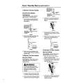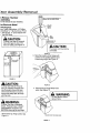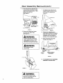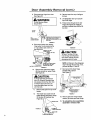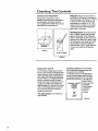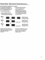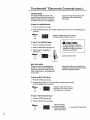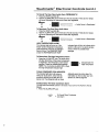
1
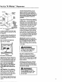
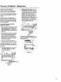
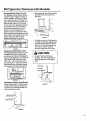
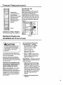
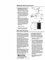
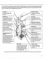
Electronic
and Non-Electronic
Side-By-Side
With Ice 'N Water
Dispenser
Refrigerator
Use & Care Manual
,4,,,a,,a 20 .,4.,,,a,,a19
_,,,a,,a 25 ._4_,,a,,a20
,4ma,,a 27 _,,,a,,a 22
_lma,,a 25
_ma.a 27
Welcome
to the
Amana
Your purchase of an Amana refrigerator/
freezer -- a household appliance known
for its quality and reliability -- is sincerely appreciated by Amana Refrigeration, Inc. Your total satisfaction with this
new product is extremely important to
us, and this Use and Care Manual will
aid you in understanding the operation
of your new appliance.
Family
returned to Amana Refrigeration, Inc. If
your registration card is missing, call
1-800-843-0304 or write:
Consumer Affairs
Amana Refrigeration, Inc.
Dept. 800
Amana, Iowa 52204
Record in the space below
the information found on the
nameplate of your refrigerator.
The nameplate is located on
the ceiling of the refrigerator
section. Also, please retain a
copy of your sales receipt for
future reference should warranty service be needed.
Each product is thoroughly tested and
checked at the factory Once in your
home, you may want to make a few simple adjustments of control settings, etc.,
to tailor your new unit to your own individual requirements. These adjustments
are easily made following the instructions in this manual.
Should your new unit ever require service, certain product information will aid
in obtaining service faster! For your convenience and protection, please record
this information in the box at right and
retain this booklet for future reference.
Serial No
Model No.__
Manufacturing No.__
Selling Dealer__
The Registration Card in the packet
with the manual should be filled out and
Recognize
this symbol
as a safety
precaution
, ,WARNING
Electrical Grounding Instructions--This appliance is equipped with a three-prong (grounding) plug for
/our protection against possible shock hazards. Where a two-prong wall receptacle is encountered, it is
the personal responsibility and obligation of the customer to contact a qualified electrician and have it
replaced with a properly grounded three-prong wall receptacle in accordance with the National Electrical
Code (see figure.)
Unit is designed to operate on a separate 103 to 126 V.A.C., 15 amp., 60 cycle line.
DO NOT UNDER ANY CIRCUMSTANCES CUT OR REMOVE THE ROUND GROUNDING PRONG PROM THE PLUG. THE UNIT MUST BE GROUNDED AT ALL TIMES. DO
NOT REMOVE WARNING TAG FROM THE SERVICE CORD.
ELECTRICAL
PLUG
ELECTRICAL
RECEPTACLE
, WARNING
DO NOT USE A TWO-PRONG ADAPTER,
ROUND GROUNDING
,DO NOT USE AN EXTENSION CORD.
Contents
Page
Electrical Warning ...............
2
Unpacking and Door Handle
Removal ....................
3
Door Assembly Removal ..........
5
Leveling, Door Alignment
and placement ...............
9
Ice 'N Water Dispenser ..........
10
General Features ...............
14
Dimensions ....................
16
Setting the Controls .............
17
Checking the Controls ............
18
Touchmatic Electronic Controls .....
t9
Refrigerator Features (All Models) ... 25
TM
2
Contents
PRONG
Page
Refrigerator Features
(27 Cu. Ft. Models) ............
Refrigerator Features
(19, 20, 22 & 25) ..............
Freezer Features ................
Optional Features ...............
Non-Use Periods ................
Sounds .......................
Care and Cleaning ..............
Save Energy ....................
Before Calling for Service .........
Amana Asure ..................
Amana Toll-Free ................
28
31
32
33
34
35
36
37
38
39
39
Unpacking
and Door
Remove all tape and packing material.
To remove tape residue, touch a portion
of the tape to the residue and lift it off. If
adhesive residue still remains, try cleaning the sticky area with a clean cloth
soaked in mild dish washing soap. Wipe
area clean. If the wood base is still
attached, have someone help you tilt
the unit onto its back, placing a sturdy
support underneath. Remove the
mounting bolts from the base and discard bolts and wood base.
IMPORTANT! Do not leave the cabinet
on its back longer than it takes to remove the wooden base and do not connect the power cord until all the inside
packing has been removed and the
cabinet has been leveled for proper
operation.
With the unit upright, pull the grille from
the bottom front and make sure the
defrost drain pan is located underneath
the defrost water drain tube. Two drain
pan side supports (attached to the cabinet bottom) keep the pan in the proper
location, to make the automatic defrost
drain water drop on the sound reducing
cone. The drain pan locating stops prevent the pan from being installed
backwards.
Handle
Removal
To Remove Door Handles with
Factory Installed Decorator
Panels
Non-Electronic
Model
Tools Required:
Tightly fitted gloves, putty knife with
tape on end, and _h6"Hex Nut Driver
1. Loosenthe upper and lowerdoor
handle trim and rotate 90 °. See
Figures 1 & 2.
ADD TAPE TO THE
F.ND OF THE PUTTY
KNIFE TO PREVENT
SCRATCHING THE
U I I .,_
DOOR PAINT _
DOOR TRIM,
UPPER
USE A PUTTY
KNIFE TO REMOVE
THE DOOR TRIM AS
SHOWN
DOOR HANDLE
FIGURE 1
O,O0
"T:"V:
Remove all tape and packing material
from inside the unit.
2THE
OOOR TRiM
IMPORTAN_
M_st Ins_l
the Defrost Drain Pan AS Shown
FIGURE 2
2. Remove the upper and lower door
handle screws. See Figure 3.
R TRIM
Model
Location of the
Defrost Drain Pan
20, 22,
25 & 27
Rightside
19
Leftside
SPECIAL NOTE: If cabinet is unable
to fit through doorway safely, you may
be requiredto removethe door handles,
or door assemblies.
DOOR HANDLE IS
SECURED WITH
TWO SCREWS
•DO NOT REMOVE
DOOR TRiM
RGURE3
.5
Door
Handle
Removal
To Remove The Door Handles
(cont.)
ADD TAPE TO THE
END OF THE PUTTY
KNIFE TO PREVENT
SCRATCHING THE
DOOR PAINT
DOOR TRIM,
Non-Electronic
Models
Tools Required:
Tightlyfitted gloves, putty knife with
tape on end, 5/16"Hex Nut Driver.
1. First remove the upper and lower
door handle trim from both doors.
See Figure 4.
ADD TAPE TO THE
END OF THE PUTTY
KNIFE TO PREVENT
II[
USE A PUTTY
KNIFE TO REMOVE
IANDLE
THE DOOR TRIM
AS SHOWN
FIGURE
6
3. Lift door trim up and pull electronic
strip out of connector as shown in
Figure 7.
'_
DOOR PAINT
FIGURE 7
SCRATCHING
USE A PUTTYTHE
KNIFE TO REMOVE
THE DOOR TRIM
AS SHOWN
_
_D_
)Oc_RRR_I_,LE
RGURE 4
,
Remove the upper and lower door
handle screws. See Figure 5.
4. To remove the trim below the door
handle follow step 2 above as shown
in Figure 6.
5. Remove the two handle screws with
a nut driver or socket wrenchas
shown in Figure 8.
NUT DRIVER
NUT DRIVER
DOOR HANDLE
_"_'_
DOOR HANDLE
"_[[
DOOR HANDLE IS
F _j
SECURED WiTH
TWO SCREWS
FIGURE
5
3. After moving the refrigerator past
doorway replace the door handles in
reverse order.
To Remove The Door Handles
Electronic Model
Tools Needed: Tightly Fitted Gloves,
Putty Knife, and 5/16"Nut Driver or
Socket Wrench.
ODOR HANDLE IS
_-_ SECURED WITH
TWO SCREWS
FIGURE 8
To Reinstall The Door Handles
Electronic Model
Tools Needed: Tightly Fitted Gloves,
Needle Nose Plier and Nut Driver.
1. With a nut driver, screw in the two
screws in the door handle.
2. Insert the electronicstrip into the slit
by pushing it in with a needle nose
plier. See Figure9.
, ,WARNING
To Avoid The Risk Of Personal
Injury, Property Damage Or Death
unplug the refrigerator before
attempting to remove the door
handles.
1,
Add tape to the end of a putty knife
to prevent scratching the door paint.
2. Use a putty knife to remove the door
electronic trim as shown in Figure 6.
FIGURE 9
3. Once strip is in place, snap the control panel trim and trim below the
handle into place.
)oor
Assembly
Removal
b Remove The Door
_ssemblies
)o not remove the door handles.)
Ion-Electronic
Model
ools Required:
_.pe,Tightly fitted gloves, # 2 Phillips
;crewdriver, s116"Hex Nut Driver, Pencil,
s" Hex Socket, 31E"Drive Ratchet and
4" Hex Nut Drive_
USE A #2 PHILLIPS SCREWDRIVER
REMOVE THE TOP HINGE COVERS
TO
PHILLIPS
DRIVER
TOP
,CAUTION:
To Avoid The Risk Of Personal
Injury first tape the top of the
doors for safety. See Figure 10.
FREEZERGOORTOP
HINGEIS
SHOWN
power cord must not be
I The
,connected.
CAUTION:
III
(3) SCREWS
ih
SECURE
FIGURE 11
EACH
3. Mark the location of the hinges with
a pencilon the painted cabinet prior
to removing hinge. See Figure 12.
TAPE DOORS
AS SHOWN
FIGURE 10
, CAUTION:
To Avoid The Risk Of Personal
Injury Or Property Damage have
two (2) people remove the door.
One to hold the door and one to
remove the safety tape, and help
with the tools.
FIGURE 12
4. Disconnect top hinge freezer door
wires. See Figure13.
WARNING:
Do Not Remove Green
Ground Wire.
,WARNING:
To Avoid The Risk of Electrical
Shock, Personal Injury or Death:
DISCONNECT the power cord
BEFORE removing the top hinge.
• Remove the top hinge covers. See
Figure 11.
FREEZERDOORTOPHINGESHOWI
FIGURE 13
r
Door
Assembly
Removal
5. First remove the toe grille then disconnect freezer door bottom hinge
water line by loosening the %" O.D.
plastic tube union nut.
See Figure 14.
(cont.)
7. The freezer door water line will
thread through the bottom hinge;
lift the door off carefully. See
Figure 16.
REMOVE TH_ Ttl_ E
CLAMP SCREW
REMOVE THE TUB_
CLAMP
WATER
IIIBE
I_OOSE
N THIS
PLASTIC
UNION
AND pULL "+HE TUBE
WATER
BOTTOM
O_ FREEZER
TUBE
O00R
FIGURE 14
FIGURE 16
,
Remove the upper door hinges,
(3) screws per upper hinge.
See Figure 15.
8. Remove the refrigerator door
assemblies by lifting off the bottom
hinge pine. Note: At this point the
refrigerator may fit through the
doorway. If not, proceed to step 9.
WARNING:
To Avoid The Risk Of Electrical
Shock, Personal Injury or Death:
DISCONNECT the power cord
BEFORE removing the top hinge.
9. Mark around the lower hinge
brackets. See Figure17.
(2) HINGE SCREWS PER
BOTTON HINGE
, WARNING:
Do Not Remove Green
Ground Wire
\
I HINGE
DEPTH
OF BOTTOM
H_NGES
USE SOCKET WRENCH TO
REMOVE AND INSTALL
HINGE SCREWS
FIGURE 17
10. To reinstall the door assemblies
assemble in reverse order.
FIGURE 15
FREEZER
DOOR
TOP
HINGE
WARNING:
It is critical that ground wires
MUST be connected when the
doors are reassembled.
6
SHOWN
Door
Assembly
Removal
To Remove The Door Assemblies (Do NOT remove the door
handles)
(cont.)
5_
CAUTION:
To Avoid The Risk Of Personal injury Or Property Damage tape the top of the doors
as shown in Figure 20.
Electronic Model
WARNING:
ToAvoid The Risk Of Personal
Injury Or Death Disconnect The
Power Cord Before Proceeding.
_
il
tools Needed: Phillips Screwdriver,
_s" Nut Driver and Tightly Fitted
3loves,
1. Remove the toe griUe.
-_,Open refrigerator door togain
access to door closure screw.
See Figure 18.
FtGtIRE 20
6, Remove the top hinge covers. See
Figure 21.
USE A PHILLIPS SCREWDRIVER
TO
REMOVE THE TOP HINGE COVERS
PHILLIPS
DRIVER
TOP
-= HINGE
COVER
FIGURE 18
FREEZER DOOR TDP
HINGE IS SHOWN
• Unscrew bottom refrigerator door
closure with a phillips screwdriver.
See Figure 18.
Disconnect at connector. Push lock
tab on underside of connector up
and then pull loose. See Figure 19.
FIGURE 21
WARNING:
To Avoid Risk Of Electrical Shock,
Personal Injury Or Death, The
Ground Wires Must Be Connected When The Doors Are
Reassembled,
7. Mark the location of the hinges with
a pencil on the painted cabinet prior
to removing hinge. See Figure 22.
GROUND
WIRE
FIGURE 19
FIGURE 22
7
Door
Assembly
Removal
(cont.)
13. Remove tape from top of refrigerator door.
8. Disconnect top hinge door wires.
See Figure 23.
Lift refrigerator door up to pull pin
up off the hinge.
Do Not Remove Green
Ground Wire.
,WARNING:
I
14.
15. Thread wires through slot in door
hinge. See Figure 26. Hinge pin
and door closures stay attached to
the door,
5/1E NUT
DRIVER
P HINGE SHOWN
PULL
THE ELECTRICAL
CONNECTDR
_ (THE FRESH FOOD TOP DOOR
HINGE IS TO BE DISCONNECTED
APART
THE
SAME WAY,)
i
FIGURE 23
9. Disconnect freezer door bottom
hinge water line by loosening the
_/4"O.D. plastic tube union nut.
3ee
_re 24.
FIGURE 26
REMOVETHE TUBE
, CAUTION:
CLAMP SCREW
REMOVE THE TUBE
To Avoid The Risk Of Preperty Damage set refrigerator
door down carefully to avoid
damaging electrical wires.
WATER
TUBE
BOTTOM
OF FRE_
DOOR
_RO_H
FIGURE
10.
NOTE: At this point,the refrigerator
may fit through the doorway. If not,
proceed to steps 17 and 18.
LOOSEN THIS PLASTIC UNION
NUT AND PULL THE TUBE
THE CLAMP
24
17, Mark around the lower hinge
brackets with a pencil.
See Figure 27.
Remove the upper door hinges,
(3) three screws per upper hinge.
See Figure 23.
, CAUTION:
(2) HINGE SCREWS PER
ROTTON HINGE
To Avoid The Risk Of Personal
Injury Or Property Damage have
two people remove the door. One
to hold the door and one to remove the safety tape, and help
with the tools.
\
11.
Remove the tape from top of the
freezer.
12.
The freezer door water line will
threadthrough the bottom hinge;
liftthe door off carefully. See
Figure 25.
HINGE
DEPTH
OF BOTTOM
HINGES
USE SOCKET WRENCH TO
REMOVE AND INSTALL
HINGE SCREWS
FIGURE 27
18. Remove the lower hinge bracket
screws. (2) screws per lower hinge.
19. To reinstall the door assemblies
assemble in reverse order,
FIGURE 25
TUBE UNION
WATER TUBE
8
LOWER HINGE BRACKET
.eveling,
Door
Alignment
.eveling
nstall the unit on a solid floor that is
;trongenough to support the combined
veightof the unit, approximately 320
bs.; and the food, maximum of 625 Ibs.
vith an approximate combined weight
_f945 Ibs.
and Placement
rear wheels. Adjust the front wheels or
leveling feet to level the refrigerator. To
raise, turn screw or leveling feet clockwise. To lower, turn counterclockwise.
See Figure 29.
[he unit must be levelto insure com)lete door closings and proper ice makng. Improper leveling will cause water
;pills and uneven ice cube size.
Fhe unitmust be level from back to
ront. This allows doors to close firmly.
fthe floor is uneven from side to side,
)lace thin metal plates under one of the
SOCKET
WRF-NCH
1/0 RAISE CABINET
ROTATE
LEVELING SCREW CLOCKWISE
FIGURE 29
)oor Alignment
C• Recheck alignment.
he doors on this refrigerator were
digned at the factory. Once the
_=frigeratoris properlyleveled, the doors
_ill be aligned. If further adjustment is
.=quired,please followthe steps below.
D. If doors are not aligned repeat
steps A through C.
• Before checking alignment, open
and close both doors to insurethey
are resting on the bottom bearings.
'.. Check alignment of door at TOP
CENTER. See Figure 30. If doors
are aligned, go to step 4.
4. If one of the front wheels is not
touching the floor (refrigerator will
rock), lower that roller only enough
to contact the floor.
j
/
//_/
///
//
/
•
/
• If doors are not aligned:
A• Lower the front wheel (turn the
screw_e_=|=r_clockwise one turn
at a time) on the side of the
refrigerator which has the lower
door. See Figure 29.
/
'ii
/
•
B. Open and close both doors.
FIGURE 30
qacement
_irto cool the condenser is drawn in the
_e grille, at the bottom front, passes
,ver the condenser, and is then
.,xhaustedthrough the same grille.
herefore, the unit can safely be
_nclosedcompletely at the top, back
_ndsides for a built-in look. Do not
,lock airflow through the toe grille at
_ottomfront of unit.
qacement of 20 Cu. Ft. Models
)n some counter tops there is a 1"
,verhang. If this is the case, the front
orners of the counter top must be
•immed off at a 45 ° angle for the
refrigerator and freezer door clearance.
This also allows for a flush installation.
See Figure 31.
A recessed electrical outlet installed
on the back wall allows for built-in
installationof your refrigerator.
Suggested height requirement for
recessed electrical outlet is 3 to 4 ft.
from floor.
.JjJJjJJ.TJJJ
FIGU RE 31
J J.
The Ice 'N Water
Dispenser
Automatic Night-Light
This is a feature that comes on automaticallywhen it's dark. If you would prefer
not to have the night-lightfeature, there
is an on/off switchjust above and
between the ice and water dispensing
bare. Push this switch in once to turn off
the night-light
The controlpanel light will also turn on
automaticallywhen dispensingice or
water if the manual swf_chis off.
Night-Light Dispenser Bulb
Replacement
Should the night-lightbulb ever need to
be replaced, it is located just above the
water dispenser bar. Replace with a 120
volt, 6 watt bulb. Sylvania 6S6 bulb or
order from your Amana Service Dept.,
part number M0360001.
Do not add ice to ice bin.
Do not try to speed ice dispensingby
adding cubes of ice that you may have
purchased or made in some other way
The unit has been "matched" to the
automatic ice maker and will not operate pmporlywith different shaped or
sized cubes.
Water Dispenser
To operate, press glass against the
water dispenser bar. Releasing pressure shuts the water off.
Some slight dripping may occur following dispensing of ice or water. If excessive, the spill should be wiped dry
immediately See Figure 33.
Do not pour water in spill shelf because
it is not self-draining -- pour it in the
k'rtchensink. The shelf and its grille
should be cleaned regularly according
to instructions on page 36.
J
10
FIGURE 33
After the unit is connected to an active
household cold water line, fill and throw
out the first 10-14 eight-ounce glasses
of water. This will cleanse the lines of
impurities.
Water taste and odor,
There are many variables which can
affect the taste and odor properties of
the water that is being dispensedfrom
your Amana Ice 'N Water model
such as:
1. Iron and other mineral deposits normally found in water.
2. Type of tubing (copper, galvanized,
plastic, etc.) used in the household
water supply system as well as the
type of tubing used to connect your
unit to your household water supply
3. Water has been left standing unused
in the storage reservoir and/or water
supply line for a long length of time.
To minimize taste and odor problems, it
is recommended that the following
steps be taken:
1. ThorOughly rinse out the system
after it has been connected to the
household water supply.This can be
accomplished by throwing away the
first 10-14 eight-ounce glasses of
water that are obtained from the unit.
2. If the water dispensing system has
not been used for an extended time,
the entire water reservoir and system
should be flushed, as instructed
above. This will ensure a fresh supply of water at all times.
If the above suggestions do not entirely
eliminate an undesirable taste or odor
condition in your water, your problem is
most likely a water problem. It is recommended that you contact your local
water treatment company for its specialized kind of help in solving your
problem.
How The Water Dispenser Works
The water reservoir is located in the
refrigerator behind the hi-humidity compartment or crisper pan, depending on
the model you have. important Note:
DO NOT REMOVE THE STYROFOAM
OR PLASTIC COVER. The water line to
the dispenser bar is routed in a special
way to prevent freeze-ups. The water
dispensing lever energizes the water
line solenoid to add water to the water
reservoir. See Figure 34.
he Ice 'N Water
ICEMAKER
TM
Dispenser
WATERUNE
TOT HE
ICE MAKER
HOME
WATER
SUPPLY
WATER
RESERVOIR
DO NOT
REMOVE
STYROFOAM
(PLASTIC)
WATERLINETO THE
WATERDISPENSER
HOW THE WATERDISPENSERWORKS
FIGURE 34
water is forced by household water
_ssurethrough the tubing and out the
ter dispenser.
me water remains in the water line to
t dispenser,causing the first glass of
ter to be somewhat warmer than the
owing glasses.
bed & Crushed Ice Dispenser
cept 19 cu. ft. model
To help meet this demand, you can
speed ice production by turning the
freezer controlto a colder setting. For
best overall operation of the unit, be
sure to return the freezer control to
its previous position as soon as
possible.
If you use very little ice over a pedod of
a week or so -- or if you use none at all
for that period -- the ice cubes may
freeze into a solid mass and the unit will
not dispense ice. You must then remove
the ice bin (follow instructions on page
13) thaw the ice and throw it away.
Overload. If you hold the dispenser bar
in the ON position for approximately 4-5
minutes, the dispenser motor may trip
out on overload. This could occur ifyou
were trying to fill a large ccntalner with
ice. The ovedoad will reset automatically
in approximately 3 minutes,after which
ice can again be dispensed.
IMPORTANT! UNDER NO CIRCUMSTANCES SHOULD YOU USE AN ICE
PICK OR SIMILAR SHARP INSTRUMENT TO BREAK THE ICE. To de so
could cause damage to the ice bin and/
or ice auger.
WARNING:
To Avoid Personal Injury NEVER
put fingers or other objects into
the ice dispenser opening.
How the Ice Dispenser Works
lect Cube or Crush Mode.
operate apply pressure against the
penser bar with a glass or other conrer. This activatesthe ice auger and
wheel which automatically delivers
)ed or crushed ice to the glass.
cept 19 cubic foot refrigerators)
lease pressure on the dispenser
r before glass is full. Do not re_vethe glass until the last of the
falls.
rmal Operation. After installation,
_illtake 4 to 12 hours before the first
•vest of ice will occur.The time rered will depend on the freezer tem"ature and the amount of food in the
_gerator and freezer section.
_=ice storage bin takes about three or
r days to fill, depending on how often
J use it.
Safety. All of the ice making and dispensing mechanisms are enclosed
within theirown compartment for safety
and for maximum storage space in the
freezer sections.
Whenever the freezer door is opened,
the ice dispenser mechanism is interrupted.This preventsthe dispensing of
ice and also insuresthat you can safely
service the ice bucket.
WARNING:
To Avoid Personal or Property
Damage NEVER attempt to operate the dispensing system with
the door open.
11
Water is automatically measured into
the ice maker, When the water freezes,
a sensor initiates the ejector blades that
dump the cubes into the U-shaped Harvester Bin, where they are held in storage for delivery. When you push the
Dispenser Bar, a large auger gently, but
firmly, moves cubes from the bin. See
Figure36.
TUeE
'_
WATER
ICEMAKER
SHUT*OFF
SUPPLY
_---
ICE MAKER
_"
_....
SHUT-OFF
SHUT'OFF
ARM
ARM
_GURE36A
.
,WARNING:
............... WATER DISPENSER
(t RAR
--...1::
.,SPENSE.
19 CU, Ft. Model Only
FIGURE 36
CAUTION:
To Avoid Property Damage Do
NOT Dispense Ice Directly Into
Thin Glass, Fine China or Delicate
Crystal.
Ice should not be dispensed directly
into thin glasses, fine china or delicate
crystal -- they can crack or chip from
the combined pressure of your hand
pressing them against the cradle and
ice dropping into the container.
Cubed/Crushed Ice 'N Water TM
Models Only.
In the cube mode the auger turns the
ice wheel in a counter clockwisedirection bypassing the crusher blades and
moving the cubes directly into the glass.
When the dispenser is in the crushed
ice mode the auger turns in the clockwise direction forcing cubes into the
crusher blades, dispensing crushed ice
directly into the glass. See Figure 36A.
To help keep bits of ice from being
sprayed beyond the glass; place the
glass close to the ice chute.
12
To Avoid The Risk of Personal
Injury NEVER attempt to manuatiy
clear the stall or jam by sticking
your hand or any foreign object up
the ice dispenser opening with the
freezer door closed, with the harvest bin in place or with the unit
plugged in.
In the case of a stall or jam, either in the
cube or crushed mode, try dispensing
in the opposite mode, several times if
necessary. In most cases this will clear
the dispenser. Do not manually attempt
to clear the ice dispenser with the
freezer door closed, with the harvest bin
in place or with the unit plugged in. TO
DO SO COULD CAUSE SERIOUS
PERSONAL INJURY.
There may be a delay when switching
between cube and crushed ice modes.
THIS IS NORMAL. Ittakes a few seconds for cubes to be moved from the
Harvest bin. Crushed ice pieces will
vary in size and shape.
Sometimes a mound of snow willform
on the door and/or ice chute. This condition is normal and usually occurs
when you have dispensed crushed ice
repeatedly The snow will eventually
evaporate.
CAUTION:
To guard against possible
water damage. If the refrigerator
will be unattended, raise the ice
maker wire shut off arm and tam
the water shut off valve for the
refrigerator to OFF.
The Ice 'N Water
TM
Dispenser
._ervicing The Ice Dispenser
,
_rtain conditionswill require you to
;ervice the ice maker and dispenser.
the unit has been designed so that you
:an do such servicing with a minimum
)f effort.
3old dry air has to circulate in the
'reezer to maintain a safe freezing temperature. Thus, cubes storedin the bin
Nilltend to evaporate and flow together
f not used regulady
Stopping Ice Production: To stop
ice production or to remove the ice
bin: take hold of wire arm near black
housing, and lift up.There will be an
audible "click" when ice maker
shuts off. The wire arm stays in the
upper position.See Figure 38. As
long as the arm is in this position,ice
will not be made. The unitwill continueto dispense cubes from the ice
bin untilall have been used.
V'oushould remove the bin and
.=mptythe contents:
• After the first few harvests of ice have
been made by a newly installed unit.
THIS IS ESSENTIAL. This allows all
impurities in the line to be flushed out
before use.
• If you are going to be gone for longer
than a week, empty the storage bin
of all ice cubes and raise the ice
maker control arm. This will prevent
the cubes from fTeezing into a mass
around the ice auger.
SHUT*OFF ARM
TO STOP THE
ICE MAKER
RGURE 38
To remove ice bin assembly: Lift up
the ice bin assembly 1/4",then pull out.
See Figure39.
• If the ice cubes become frozen to
each other and around the ice auger.
Ice maker control arm. The wire control arm on the automatic ice maker has
2 functions:
1. Normal Operation: the wire arm is
in the down position;ice willbe
made. See Figure37.
FIGURE 39
I TM
_
POSITION
EXTENSION
RGURE 37
13
General
Features
Freezer Sliding Storage Shelf
Frozen Juice Can
RefrigeretodFreezer
Controls (Non.Electronic
Models)
Upper Refrigerator
Light
Adjustable
Shelves
Top Freezer
Door Shelf
Egg Storage
Ice Bin
Containers
Ice 'N Water
Dispenser
Dairy Module
Temperature
Beverage Chiller
Adjustable
Freezer
Bottle Rack
Shelf
Huggers
_.djustabie
:raeger
)oor
_helves
Me_
Keeper Control
ight
Meat Keeper
Retainers
ustable
Shelves
Toe Grille
and Condenser
Glide-out
Basket
(Behind Toe Grille)
Freezer
Controlled Crispers
Drawer Controls
Power switch (Located behind the toe grille in the center on the electronic mode| only ),
IMPORTANT NOTE:
Model shown is for a 27 cu. ft. refrigerator
FEATURES MAY VARY FROM MODEL TO MODEL. YOUR REFRIGERATOR MAY NOT HAVE ALL THE
FEATURES SHOWN.
_4
Dimensions
DIMENSIONS
P
ICE 'N WATER
(ALL DIMENSIONS IN INCHES)
681/2
r_
47/B" --_]
_'-"K"
"-_
2s/a " --b.
t
"N"
;'L"
"C"
DEPTH DEPTH
"M ....
N"
CABINET DOOR
INCL. FRZDOOR REFDOOR
MODEL WIDTH REMOVED HANDLE OPEN90° OPEN
900
19"
32
27
31%
43
44%
,,,,,I
20*
353/4
23_h
28%
39%
451/4
22*
35¥4
26
307k
42%
47_
25*
35_
28a/4
33%
447k
50%
35_4
26¥4
3_4
44%
50Y2
27**
*Mustbeinstalled
_k" fromsidewallsfor90° dooropening.
**Mustbeinstalled
4%"from sidewailsfor90odooropening,
Allow%" ontopandsidesforeaseofinstallation.
16
etting
the Controls
:reezer Control
l'his is the main control located on the
Jpperback wall of the fresh food secion. Non-electronic models only. See
:igure 43. If it is turned OFF, neither the
--reezernor the Refrigerator will cool. All
)f the electrical circuits remain
,_nergizedexcept for the compressor
_nd fan motors. The control has seven
_ettings, from "1" (the warmest) to "7"
the coldest). Start by settingthe dial on
'4". Load food in freezer, Allow 24
lours for the freezer to coot after the
Jnitis installed, before checking food
emperatures.
remp-Assure" Thermostatic
:refrigerator Control
I'his control,located on the upper back
_/allof the fresh food section, operates
ndependentlyof the freezer control.
Yon-electronic modelsonly. See Figure
€4. A hidden thermostatic sensormeasJres refrigeratorair temperature constantly, and automaticallylets in more
;old air if temperature rises as
titUeas 1V2°Ffrom your setting.
FIGURE 43
Check Food Temperature as
instructed on page 18. Adjust the control as needed one number at a time.
The best temperature for frozen food
storage is in the 0 ° to 2°F range.
The control has seven settings, from
"1" (the warmest) to "7" (the coldest).
The best food storage temperature is in
the 38 ° to 40°F range. Start by setting
the dial on 4. Load food in the refrigerator. Place a glass of water on the middle
shelf of the refrigerator section, making
sure that air can flow around it. (This
will be used later to check food temperature.) After the unit is installed, allow
24 hours for the refrigerator to cool.
Check food temperature as instructed
on page 18. (Adjust the control as
needed, one number at a time.)
FIGU RE 44
bmperature Controlled Beverage
;hiller Control
rotary dial control, located on the left
_ner wall of the refrigerator section,
dlows you to adjust the amount of
reezer air that circulates into the beveragechiller. See Figure 45. This keeps
_everages up to 5 degrees E colder
ban the rest of the refrigerator. Turn the
vheel clockwise for the coldest temper_tures and counter clockwise for
varmer temperatures.
On the outsidewall of the refrigerator
door is the air inlet which allows freezer
air to pass to the beverage chiller, See
Figure 46. The additional cold air can
affect the refrigerator compartment temperature, so the Temp-Assure Thermostatic Control may require adjustment
after the beverage chiller temperature
has been set.
TM
@
_
FIGURE 45
FIGURE 46
17
Checking
The
Controls
FREEZER: Place the thermometer in
the center of the freezer, surrounded by
frozen packages. See Figure 47. Wait 5
to 8 hours, then check the reading. If
temperature is not within 0 ° to + 2°F,
adjust control as needed, one number
at a time and check the temperature
again after 4 to 6 hours.
Checking Food Temperature
Twenty-fourhours after the unitis
installed, check the food temperature in
the refrigerator and freezer sections.
Use a quality thermometer that can register balow-zere temperatures.
N
/
FROZEN FOOD
PACKAGES
REFRIGERATOR: Place the thermometer in a glass of water and place the
glass in the middle of the refrigerator
section. See Figure 48. Be sure air can
flow around it. Wait 3 to 4 hours, check
the temperature and adjust the control
one number at a time as needed to
within the 38 ° to 40°F range. Wait 3 to
4 hours and check the temperature
again.
RGU RE 47
GLASS
OF WATER
FIGURE 48
Energy Saver Control
The 2-Position Energy Saver Control
lets you save energy by adjustingrefrigerator operationto the humiditylevel in
your house. See Figure49. During hot,
humid weather, any refrigerator/freezer
willform moisture aroundthe doors,
similar to the way condensate forms on
a glass of ice water.The cabinet has
special heaters to minimize this condensation. The Energy Saver Control lets
you controlthe amount of heat the
heaters are givingoff.
The upper position is for periodsof
high humidity.
The lower position turns the heaters
off for maximum energy savings. Use
for periodsof low humidity.
A minimum amount of condensationis
normal. During extreme high humidity,
condensate may also form on the cabinet sides and
doors. This is
normal and will
ENERGY
SAVER
REI_fJ_E_5
disappear
EXTI_I_:3_
I_AI_ET
when climatic
_STURE
conditions
return to
normal.
s _,,'EN
EpdEI_I_%"
FIGURE
18
49
Touchmatic
TM
Electronic
The Amana Touchmatic Electronic Center gives you the freedom of controlling
your refrigerator from a simple-to-operate control panel located above the
door handle on the exterior of your
refrigerato_
The Touchmatic Control Center alerts
you when a door is open, when the
freezer/refrigerator temperature is too
high and even when you need to clean
the condenser coil, plus much more.
To ensure that your new Amana Touchmatic Electronic Refrigerator operates
correctly follow the simple-to-operate
instructions on the following pages.
BEFORE YOU GET STARTED .......
When your refrigerator isfirst plugged
in, the temperature indicator lights will
blink. Press the START pad (the -_) or
ALARM OFF pad.
Controls
POWER
SWITCH
Located behind the toe grille in the center is a switch. This switch must be in
the on position before you proceed any
furthe_
NOTE: The alarm may go off in (2) two
hours and the High Temp indicator light
flash, if the refrigerator and freezer have
not been cooled to the proper temperature. Deactivate alarm by pressing the
ALARM OFF pad.
POWER
SWITCH
START pad
To activate the control panel first press
the START pad (the -_). This will be
referred to as the
START pad in the
remaining sections.
Pressing this pad will:
27
1. Turn the temperature indicator
lights on.
2. Allow you to use
any of the other pads on the control
panel. If you do not press the START
pad, none of the pads will operate
except the ALARM OFF pad.
NOTE: Once activated, the pads will
remain programmable for at least 10
minutes.
OPTIONAL ENTRY TONE
Your refrigerator is designed to give you
the option of a 'peep' signal whenever a
pad is pressed. This signal lets you
know the control has 'read' and
accepted your command. The entry signal has been pre-set on your control
panel and will 'beep' when a pad is
pushed. If you wish to cancel the 'beep'
signal follow the directions below.
To Cancel The Optional Entry Tone:
1. Press and hold the START pad
(the-_-) for approximately (3) three to
(5) five seconds. Three (3) short
beeps will sound indicating the
instructions have been registered. To
reactivate the entry signal, repeat the
above process.
19
Touchmatic
TM
Electronic
Controls
(cont.)
TEMP-ASSURE _ THERMOSTATIC REFRIGERATOR CONTROL
An Electronic thermostatic sensor
measures refrigerator air temperatures
constantly and automatically lets in
more cold air if temperature rises as
little as 1_/2°Ffrom your setting.
PROGRAMMING
YOUR REFRIGERATOR
TEMPERATURE SETTINGS
With the Amana Touchmatic Electronic
Control, you can precisely control the
temperature in the refrigerator and
freezer sections without even opening
the doors, The freezer temperature and
the refrigerator temperature may be
changed independent of one another.
The temperature of each can be set at
one of nine temperature levels. One (1)
being the warmest and nine (9) the coldest. When changing the temperature,
the temperature indicator lights will be
on. The indicator lights will tell you
whether the freezer or refrigerator temperature is being changed and what
level the temperature is currently at.
To Set Or Change The Temperature In The Refrigerator
The control has nine settings, from '1'
3. The starting temperature setting in
(the warmest) to '9' (the coldest). The
the refrigerator is setting number 5.
best food storage temperature is in the
4. Press the WARMER pad or
38 ° to 40 ° range. Start by programming
COLDER pad to raise or lower the
your controls as follows:
temperature setting one level at a
time. Continue to hold the WARMER
1. Press the START pad (the :_).
pad or COLDER pad down to raise
2. Press the REFRIG TEMP pad. This
or lower the temperature more than
tells the control panel you want to set
one level at a time.
the temperature in the refrigerator.
OR
+
....................
Raises or Lowers
= Temperature Setting
One Level At A Time
Lowers Temperature
= Setting More Than
One Level At A Time
Continue to Press Down
....................
Raises Temperature
= Setting More Than
One Level At A Time
Contir_ue to Pre_s Dc_vn
Load food in the refrigerator. Place a
thermometer in a glass of water in the
middle of the refrigerator section, making sure that air can flow around it.
(This will be used later to check food
2O
temperature.) After the unit is installed,
allow 24 hours for the refrigerator to
cool. Check food temperature as
instructed on page 18. Adjust the control as needed, one number at a time.
Touchmatic
TM
Electronic
Controls
(cont.)
To Set Or Change The Temperature In The Freezer
The control has nine settings, from '1'
(the warmest) to '9' (the coldest). The
best food storage temperature is in the
0° to +2°F range. Start by programming your controls as follows:
1. Press the START pad (the :_)
2, Press the FREEZER TEMP pad.
This tells the control panel you want
to set the temperature in the freezer.
3. The starting temperature setting in
the freezer is setting number 5.
4=
Press the WARMER pad or
COLDER pad to raise or lower the
temperature setting one level at a
time. Continue to hold the WARMER
pad or COLDER pad down to raise
or lower the temperature more than
one level at a time.
,t4_Hfna,
27
+
+
Raises Or Lowers
= Temperature Setting
One Level At A Time
OR
OR
_gHIItMa,
27
+
Raises Temperature
= Setting More Than
One Level At A Time
4eee=ee=eeeeeeweeeee
ContJr_u8
to Press
Down
OR
27
4eeeeeeeteeeele.=e=e
Lowers Temperature
= Setting More Than
One Level At A Time
CoatinLe to Press Down
.oad food in the freezer Place a ther"nometer between the frozen food in the
"niddleof the freezer section. (This will
)e used later to check food
emperature.)
After the unit is installed,allow 24 hours
for the freezer to cool. Check food temperature as instructed on page 18.
Adjust the control as needed, one
number at a time.
21
Touchmatic
TM
Electronic
VACATION MODE
The Vacation Mode is ideal for when
you will be away from your home for an
extended amount of time, but sti_lwish
to preserve the food in your refrigerator.
Controls
(cont.)
During this mode the refrigerator will
defrost less often, saving energy
and money.
To Start The VACATION Mode
1. Pressthe START pad (the _).
2. Pressthe VACATION pad, The vacation indicatorNightwill come on acknowledging your
_'ommand.
Vacation Indicator Light Will Come On
Indicating Vacation Mode Is Now On* *
_WNWMS,
27
+
CAUTION:
To Cancel The VACATION Mode
To Avoid The Risk Of Property
Damage see pages 13 and 34 for
important ice maker instructions
, during non-use periods.
1. Press the START pad (the _K':).
2. Press the VACATION pad again OR
3. Open e_therthe refrigerator or
freezer door.
27
+
= Cancel Vacation Mode
OR
Open Door
MAX COOL MODE
During this mode, the refrigerator temperature is reducedto the coldest set
pointfor ten (10) hours. Ideal if you like
colder chilled drinks or have added a lot
of warm food.
After the ten (10) hour time period the
refrigerator temperature will return to the
previous temperature setting,
To Start the MAX COOL Mode
1, Press the START pad (the_).
2. Press the MAX COOL pad. The MAX COOL indicatorlight will come
on acknowledging your command.
_nu,
27
+
=
Indicator Light Will Come On
Indicating The Control Panel
Has Heard Your Command
To Cancer The MAX COOL Mode
1. Press the START pad (them),
2. Pressthe MAX COOL pad again.
Will automatically
_NBna
27
22
+
OR return to previous
temperature setting
after (10) ten hours.
= Cancel MAX COOL Mode
Touchmatic
Electronic
FAST FREEZE MODE
This mode reducesthe freezer temperature to the coldestset point for 24 hours.
Ideal for freezing large amounts of food
Controls
(cont.)
quickly. After the 24 hour period the
freezer will automatically return to the
previous temperature setting.
To Start The FAST FREEZE Mode
1. Pressthe START pad (the:_).
2. Press the FAST FRZ pad. The FAST FREEZE indicator light will come on acknowledging your command.
Jl_NIl_lraB,
27
The FAST FREEZE Indicator Light Will
Come On Indicating The Fast Freeze
Mode Is Working
+
To CancelThe
FAST FREEZE Mode
1+ Press the START pad (the -_,_).
2+ Press the FAST FRZ pad again.
Will Automatically
return to previous
OR temperature setting
after (24) twenty-four
hours.
,t4_lllSnB+
27
+
=
Cancels The
FAST FREEZE
Mode
To Cancel The Temperature Display Lights
1. Pressthe START pad (the _(_)+
2. Pressthe DISPLAY OFF pad.
,_J_mana,
+
= Temperature Display Lights Will Turn Off
27
To Reactivate The Temperature Display Lights
1. Press any of the top (5) five pads,
27
+
OR
OR
OR
Wil! Activate The Temperature Display Lights
SIGNALS TO ALERT YOU
Audio and visual signals have been
specially designed into your refrigerator
to quickly alert you to conditions you
might not be aware of if you owned a
conventional refrigerator.
DOOR OPEN ALARM
The indicatorlight will come on whenever either door is open. If either door is
open continuously for three (3) minutes.
the indicator light will blink and an alarm
will sound,
To Discontinue The Door Open Alarm
1, Press ALARM OFF
or close the door(s).
ALARM
OFF
OR
=
CIcse Door
Discontinue The Door Open Alarm
23
Touchmatic
TMElectronic
Controls
(cont.)
To Cancel The Door Open Audio Alarm PERMANENTLY
!. Pressthe START pad (the_)_).
2. Hold the ALARM OFF pad for three (3) to five (5) seconds. Three (3) short beeps
will sound indicatingthe instructionshave been registered.
=J7
P_Downfor3_Ssecond$
= AudioAlarm Is Deactivated
*1"
To Reactivate The Door Open Audio Alarm
1, Pressthe START pad (the_).
2. Hold the ALARM OFF pad for three (3) to five (5) seconds. Three (3) short beeps
will sound indicatingthe instructionshave been registered.
27
=1"
Press Down for 35 seconds
=
Audio Alarm Is Reactivated
HIGH TEMPERATURE ALARM
The indicatorlight will come on ifthe
freezer and/or refrigerator temperature
gets excessivelywarm for an extended
period of time. The FREEZER TEMP
and/or the REFRIGERATOR TEMP
indicatorlight will blink to indicate which
section istoo warm. An alarm willalso
sound. Check for possiblefood
spoilage.
To Discontinue The High Temperature Alarm
1. Press the ALARM OFF pad. The audio alarm
willalso discontinueif the proper temperature
is regained in the refrigerator and/or freezer
sections. Check for possiblefoodspoilage.
NOTE: You must press ALARM OFF to clear
the high temperature indicatorlight,
CLEAN CONDENSER COIL INDICATOR
The indicator light alarm willcome on,
withoutan audio alarm, everythree (3)
monthsto remind you to clean the condenser coil.The refrigerator willrun more
=
Discontinues The
High Temp Alarm
efficiently when the coil is clean. For
informationon how to clean your condenser coil, refer to page 36.
To Discontinue The Clean Condenser Alarm
The light willautomaticallycancel in 72 hours or you can turn it off priorto that as
follows:
1. Press The ALARM OFF pad.
ALARM
OFF
=
To Cancel Clean Condenser
Coil Alarm
Refrigerator
Features
Refrigerated Meat Keeper Control
The Refrigerated Meat Keeper features
a drawer inside a wrapper or sleeve. A
control,located in the front trim, allows
you to adjustthe amount of freezer air
that circulates between the drawer and
sleeve to keep meat up to 5°F colder
than the restof the refrigerator.See Figure 50. Slide the controlto the left for
the coldesttemperatures and to the
rightfor warmer temperatures,The
additional cold air can affect the refrigeratorcompartment temperature, so the
Ternp-Assure thermostaticcontrolmay
requireadjustment after the Meat
Keeper temperature has been set.
(All Models)
1. Tap upwards at rear of shelf near the
tracksto loosen shelf hooks, See
Figure 53.
F__
TM
2. Lift shelf and pullout. See Figure 54.
To install, tilt shelf and engage upper
hooks in desired track slots. Lower
shelf front and tap downwards near
the tracks until shelf hooks are
securely seated and shelf is level
FIGURE 50
Refrigerated Meat Keeper Drawer
The Refrigerated Meat Keeper must be
installedwith its cold air supply tube
covering the air inlet port completely.To
ensure properalignment, only insert the
upper hooks of the shelf into the 9th,
10th, 11th or 12th track slotsfrom the
top. See Figure51. Otherwise food will
freeze below the uncoveredair supply
hole, located in the back left side wall.
It!
I
FIGURE 53
CAUTION:
To Avoid The Risk Of Property
Damage - Test shelf installation by
applying pressure to front edge of
shelf,
, II
10 !.
FIGURE 51
Adjustable Cantilever Glass Shelves
These shelves attach to metal tracks at
the back of the interior,See Figure52.
To removethe Cantilever Shelves, follow the instructionsbelow.
FIGURE 54
Jl
_r
li
II
/
FIGURE 52
25
Refrigerator
Features
Refrigerated Meat Keeper and
Humidity Controlled Crisper Drawer
Removal
(All
Models
cont.)
3. Pull drawer out the rest of the way.
See Figure 57.
Boththe Refrigerated Meat Keeper and
Humidity Controlled Crisper Drawer
may be removed for easy cleaning by
following these easy to follow
instructions.
1. Pull the drawer three quarters of the
way out, See Figure 55,
FIGURE 57
Humidity Controlled Crisper
Drawers
These drawers are for storage of fresh
fruits and vegetables. It is normal for
moisture to accumulate inside.See
Figure 58.
FIGURE 55
2. Lift up slightlyto release notches in
the grooves. See Figure 56.
FIGURE 58
FIGURE 56
26
Refrigerator
Features
Crisper Drawers can be pulled out fully,
even when door is opened at a go°
angle. At a 90 ° door opening the two
lower door shelves must be removed to
completely take out the crisper. See
Figure 59.
FIGURE 59
Hi-Humidity Drawers have a control
to regulate humidity inside.Set high
humidity for leafy vegetables such as
cabbage and lettuce, and set low
humidity for produce with skins such as
apples and tomatoes. On models with
humidity control, slide control to the left
for high humidity and to the right for low
humidity See Figure 60.
FIGURE 60
Bottle Rack
This rack hangs from a shelf and holds
a large bottle within easy reach. It is
shipped inside a crisper drawer. To
install, hook tabs on flat portion of rack
over the side metal frame of any shelf.
The shelf may have to be tilted up or
removed temporarily. Be sure bottle cap
is on tightly before placing a bottle in
the rack. See Figure 81.
(cont.)
If Light Bulb Needs Replacing:
• Unplug unit frem wall outlet to avoid
electricalshock. A pair of gloves
should be worn as a precaution
against broken glass.
Refrigerator Compartment
1. Unscrew the light bulb(s) located on
the front upper wall of the refrigerator
compartment by turning
counterclockwise.
2. Replace with a 40 watt G.E. or
Westinghouse #40A15tl, Sylvania
#40A15 or order from your Amana
Service Dept., part number
A0282803.
Freezer Compartment
To remove the light bulb located on the
right wall of the cavity,directly below the
ice bucket of the upper freezer compartment, follow the directions below:
1. Remove the ice makerdrawer.
2. Remove the protectiveshield by
unscrewingthe nut with a 1/4"drive
or socket wrench.
3. Unscrew the light bulb
countemlockwise,
4. Replace with a 40 watt G.E. or
Westinghouse#40A1511, Sylvania
#40A15 or order from your Amana
Service Dept., part number
A0282803.
Dispenser Light Bulb
Should the light bulb ever need to be
replaced, it is located just above the
water dispenser bar.
1. Unscrew the bulb counterclockwise.
2. Replace with a 120 volt, 6 watt
Sylvania 6S6 bulb or order from your
Amana Service Dept., part number
M0360001.
,,,,,w,w
)
FIGURE 61
27
Refrigerator
Features
Stor-Mor ® Door
(27 Cu. Ft. Model Refrigerator)
Egg Storage. A removable take-tocounter egg bucket stores eggs in a
see-thru covered container. See Figure
62. To clean, handwash in warm
soapy water.
(2 7 Cu. Ft. Only)
1. Lift the front part of the shelf up and
pull out at an angle, See Figure 65.
Egg Storage. A removable take-tocounter egg bucket stores eggs in a
see-thru covered container. See Figure
62, Toclean, handwash in warm
soapy water.
RGURE 65
2, Slide the front trim right or le_tto
remove from the shelf floor. See
Figure 66.
FIGURE 62
Dairy Storage, Store butter and
cheese in an adjustable dairy module
complete with three food storage containers and three dairy compartments
with sliding door. See Figure 63.
FIGURE 66
FIGURE 63
Dairy Storage Door
The sliding door is removable for easy
cleaning. Grasp the bottom of door and
gently lift up and out. The door will bend
slightly to allow removal from track. See
Figure 64.
3. Replace the front trim by sliding the
trim intothe compartment area without the shelf. See Figure 67. When
the shelves are removed either one
or both sides can now be used as a
tall package shelf. See Figure 68
and 69,
RGURE 64
Dairy Storage Shelves
The Dairy Storage Shelves within the
dairy module can be removed easily for
cleaning or storage of taller items.
28
FIGURE 67
Refrigerator
Features
(2 7 Cu. Ft.
Only
cont.)
To gain access to the beverage chiller
area slide the door upward. See
Figure 72.
FIGURE 68
FIGURE 72
FIGURE 69
Food Storage Containers. Some
models feature three durable left-ever
containers.See Figure 70. They store
convenientlyin this compartment and
slide out for easy access. Containers
are microwave* and dishwasher safe.
(Always place in the top rack of
dishwasher).
Note: If containersshouldstain,follow
manufacturer'sinstructionsfor cleaning.
The sliding door will remain in the
upward position until guided down to
the closed position, See Figure 73, The
extra deep door bucket allows for storing gallon size items and other large
beverage containers.
FIGURE 73
Chiller Bucket Removal
The Chiller bucket may be removed
easily for cleaning. To remove the
bucket follow the instructions below.
FIGU RE 70
*Note: Be sum to follow manufacturer's ir_truc tions, located in the containers when using containemeto REHEAT foods in a microwave even.
1. Take hold of bucket. See Figure 74.
Temperature Controlled Beverage
Chiller
FIGURE 74
FIGURE 71
29
Refrigerator
(2 7 Cu. Ft.
Features
Only cont.)
2, Push the Ioc-tabs toward the center
with your thumbs or forefingers,
whichever is easier for you, See
Figure 75. While holding in the Ioctabs, pull the bucket straight out,
3. Take care to retain the four retention
glides. See Figure 78. These will be
needed to reinstall the door,
_
I ./
RETENTION
GLIDES
FIGURE 78
FIGURE 75
3. To install the Chiller Bucket, slide
bucket intogrooved area until the
tabs lock into place, See Figure 76.
\
4. Reverse steps f and 2 to reinstall
the door,
Door Buckets. There are three deep
door buckets that can be moved up or
down to fit storage needs, The deep
door buckets allow for easy storage of
six-pack items for convenience. See
Figure 79. To remove the door buckets
follow the instructions on page 29 for
chiller bucket removal. To installthe
door buckets follow the instructions on
page 30.
FIGURE 76
Chiller Door Removal
The Beverage Chiller Door may be
removed for cleaning by following the
instructionsbelow.
1. Remove the Chiller Bucket as stated
above.
2. Slide door down and out throughthe
bottom of the track. See Figure77.
FIGURE 79
Hugger. A handy bucket hugger slides
back and forth along 'chiller' bucket to
prevent items from falling over, See Figure 80.
FIGURE ?7
30
RGURES0
Refrigerator
Features
(19, 20, 22 & 25 Cu. Ft. Models)
Stor-Mor
_ Door (19, 20, 22
and 25 cu.-ft.
Refrigerators)
Egg Storage. A removable take-tocounter egg bucket stores eggs in a
see-thru covered container See Figure
81, TOclean, handwash in warm
soapy water.
FIGURE 83
FIGURE 81
Dairy Storage. On 20, 22 and 25 cubic
foot models, store butter and cheese in
an adjustable dairy module complete
with top door full-length shelf, two dairy
compartments with sliding door and
three food storage containers, The 19
cubic foot model features one large
dairy compartment with two condiment
trays and three food storage containers.
See Figure 82. (Note: When washing
butter dish, place dish on top rack of
dishwasher.)
Door Shelves. Some models feature
door shelves that can be moved up or
down to fit storage needs. See Figure
84, To remove loosen shelf by tapping
upwards gently underneath both ends.
Lift shelf slightly(1),then rotate bottom
out and up to release mounting hooks
from door slots (2). To install, tilt shelf
and insert upper hook into any two door
slots as shown. Rotate shelf bottom
towards door and insert bottom hooks
into door slots. Hold shelf against door
and tap down gently on both ends until
shelf is seated securely
TO REMOVE
FIGURE 84
Huggers. Some models feature two
handy shelf huggers that slide back and
forth along door shelves. See Figure 85.
FIGURE 82
Food Storage Containers. Some
models feature three durable leftover
containers,See Figure 83. They store
convenientlyin this compartment and
slide out for easy access, Containers
are microwave* and dishwasher safe.
(Always place in the top rack of dishwasher).
Note: tf containers should stain, follow
manufacturer's instructions for cleaning.
RGURE 85
* Note: 8e sure to follow manufacturer's instructions,
Iocated in the cot)_aine_s, whet} using containers to
REHEAT _ods in a microwave oven.
31
Freezer
Features
Retainer Bar islocated above the ice
chute. See Figure 86. The bar is removable for easy cleaning_Pull the bar left or
right and up to remove. See Figure 87.
Adjustable Freezer Shelves
1. To remove, press tabs on shelf
support on right side of wall, lift shelf
out of support tabs. See Figure 89.
SUPPORT
TABS
FIGURE S9
2. Pull shelf sideways and up until shelf
rods come out of holes in the left
wall. See Figure 90.
FIGURE 86
ROLE
FIGURE 87
FIGURE 90
Freezer Door Buckets. The door
buckets can be moved up or down to fit
storage needs. To removethe freezer
door buckets follow the same procedure
as refrigerator door bucket removalon
page 29.
3. Select the desired shelf height and
insertthe shelf rods infothe holes on
the left wall, lower the shelf onto the
support tabs and press down until
the shelf snaps into place. See
See Figure 91.
Large Glide-Out Freezer Basket
Stores odd-shaped, bulky food items.
See Fkjure 88.
; SuPPeR1
TAB_
FIGURE 91
FIGURE 88
Automatic Free-O'-Frost Operation
The freezer and refrigeratorsections are
completely frost-free. The Amana FrostMagnet® evaporatorcoil in the back
wall stops frost beforeit starts. Under
normal operating conditions,you'll
never have to defrostthe unit, because
it's automatic.
TM
32
Tall Package Retainer (20 & 27 ¢u. ft,
Refrigerators)
Allows placement of tall packages in
door buckets. Retainers will keep packages securely in place. See Figure 92.
Freezer
Features
(cont.)
Freezer Door,
The freezer door has
three adjustable
shelves, one non-adjustable shelf and one
retainer bar. See
Figure 93. To remove
see instuctions on
page 29.
Removable Door Dike
(20 cu. fit, only)
Designed for kitchens when space limitations restrict opening of door to 90 °,
Removable door dikes (closest to
hinges) will snap out to allow removal of
freezer basket and ice bucket. To insert
door dike align the four push clips to the
holes on the freezer door. Snap in until
the door dike is locked intoplace. See
Figure 94.
FIGURE 93
Automatic Ice 'N Water Dispenser
See instructions beginning on page 10.
TM
Optional
Available
Features
At Extra
CAUTION:
To Avoid Property Damage to soft
vinyl flooring follow floor products
manufacturer's recommendations
when installingor moving the
refrigerator.
Your Amana has several optional convertible features that you may purchase
from your Amana dealer.
Decorator Panels (Some Models)
These Amana units come from the factory with doors ready to decorate almost
any way you want.
Amana does not manufacture decorator panels for individual sale. Consult your dealer, cabinet maker or
kitchen remodeler for sources.
Match wood cabinetry. Your Amana
dealer has a special 1/4-inchtrim kit,
available at extra cost, which allows you
to have special wood panels built and
installed on your unit so it matches the
rest of your kitchen cabinets. (Panels
not furnished.)
FIGURE 94
Cost
How to install decorator panels.
Dimensions for 1/16"panels:
• 20, 22 and 25 cu. ft. models -Upper Freezer Door Panel -141/4
" W x 17%" H; Lower
Freezer Door Panel -141/4" W x 32s/32" H;
Refrigerator Door Panel -181%2"W x 617/6'_H.
,, 19 eu. ft. model -- Freezer Door
Panels -- same as 22 and 25 cu. ft.
models; Refrigerator Door Panel
1423/32
" W x 61%" H.
Tools Needed -- Standard screwdriver,
Phillips screwdriver, masking tape and
tightly fitted gloves.
1. Remove trim cover from hinge
side of door. Tape tip and shaft of
standard screwdriver to avoid marring the unit. Place screwdrivertip at
top of trim cover next to hinge pin
and push rear edge of trim out to the
side. Working down the door, lift the
rear edge of the trim cover to the
side until it snaps off the trim
retainers.
2. Unscrew and remove the trim
retainers.
33
Optional
Features
(cont.)
3. Guide panel into channels in the
top and bottom trim and slide
panel across the door and underneath the door handle. Press panel
or squeeze door handle as needed.
4. Replace the trim retainer. Hook
trim cover onto the front edge of the
trim retainer, then gently tap back of
cover with base of hand until cover
is firmly seated along its entire
length.
5, NOTE: On models having black
handles and trim it will be necessary
to modify a small black plastic shim
located behind the top end of the
upper trim piece on the handle side
of the door. Remove shim by sliding
part to the left on the freezer door
and right on the refrigerator door.
See Figure 95.
,Trim
DoorRefrigerat°rShim
_
Black Door Trim
Score Line
FIGURE 95
Shaded
Snap OffSection
------_
Along Score
Line
t14"
Shim
FIGURE 96
/
Freezer
DOOr
Shim
Modify per Figure 96.
Reinstall shim by simply sliding it
back into place, See Figure 97.
FIGURE 97
Non-Use
Periods
Vacation Time. If you will be away for
vacation, remove perishable foods from
the unit. Shut off the ice maker by turning off the water supply to the refrigerator and moving the ice maker wire arm
to its upper-most position.
Extended Periods of Non-Use. If you
are going to be away for longer periods,
empty and unplug the unit. This will
reduce needless operation and assure
that food will not be spoiled if electrical
service is interrupted. Just clean the
unit as instructed in this manual and
prop open the doors so air can circulate
inside. Leave the unit unplugged. If the
refrigerator has an automatic ice maker,
turn off the water supply to the
refrigerator.
When You Move. Unplug the unit and
clean it. Use strapping tape or masking
tape to secure all trays, shelves and
other parts to preventdamage during
shipment. Do not leave the unitclosed
for an extended period of time.
CAUTION:
To Avoid Property Damage do
NOT use tape that has "permanent" type adhesive!
If The Refrigerator Will Be Stored,
If the refrigerator will be stored or
remain unused in a sub-freezing envirenment, remove the water and protect
the water valve from damage as follows:
I. Disconnest the refrigerator from the
electrical power source.
Shut off the refrigerator water supply
This can be done at the saddle valve
where the _!4"copper supply tubing
joins the household water line. (Refer
to illustration on back of cabinet.)
2.
.
Remove the compressor compartment cover from the bottom rear of
the refrigerator to reveal the water
valve coupling. Place a small container under the valve to catch water
spills. Remove the brass hose fitting
from the valve. Label the two plastic
tubes attached to the valve.
Unscrew the compression nuts from
the tubes and push the ends of the
tubes away from their valve fittings.
See Figure 98.
4. Blow the water out of the water disdenser plastic tubing with compressed air.
Yournewrefrigerator
maybereplacing
asmallerrefrigerator
ofdifferent
designand/ora product
whichoperated
lessefficiently.
Steps
havebeentakeninproduct
designandoperation
oftoday'smodern
refrigerator
whichcontinue
toprovide
thehighest
qualityproduct,
onewhichisenergy efficient and operates as economically as possible. With this new design, you may hear sounds which are unfamiliar to you, yet quite normal and do NOT require a service call.
ICE MAKER
FREEZER CONTROL
Ice cubes will drop out of the
automatic ice maker into the
ice bucket.
The freezer control will click
when starting or stopping the
compresso_
FREEZER FAN
ICE AUGER
The fan circulates cold airto cool
the refrigerator, and the freezer
compartment and sounds like air
rushing or a whirring sound.
When dispensing ice, the ice
auger agitates the ice out and
the drive motor makes a humming
sound.
EVAPORATOR
DISPENSING CRUSHED ICE
The flow of refrigerant through the
freezer cooling coil sounds like boiling water or a gurgling noise.
Chopping and ice crushing noises
occur when dispensing crushed ice.
COMPRESSOR
DEFROST HEATER
The new high efficient compressor
runs faster and will have a higher
pitch humor pulsating sound while
operating.
Water dropping on the defrost
heater causes sizzling, hissing or
popping sounds during the defrost
cycle.
CONDENSER FAN
ICE MAKER WATER VALVE
HOOK-UP
The water valve will buzz when the
ice maker fills with water or when
you are dispensing a glass of wate_
This occurs whether or not the
refrigerator is connected to the
household water supply In the event
your refrigerator has not been
hooked up to water, you can stop the
sound by raising the Ice Maker shot
off arm to the 'up' position.
The outside condenser fan circulates air to cool the condenser and
makes a whirring sound.
DEFROST DRAIN PAN
\
Defrost water falls into the drain pan
during the defrost cycle. The drain
pan must be positioned between
the retainers orthe drain pan
may rattle.
INSULATION
DEFROST TIMER
Foam insulation is very energy efficient and has excellent insulating
capabilities; however, it does not
provide the high level of sound
insulationprovided by the less efficient fiberglass insulation once
used by manufacturers.
The automatic defrost timer
sounds like an electric clock
and snaps in and out of the
defrost cycle.
All of these sounds are usual and will soon become familiar, They indicate the unit is operating and performing as designed.
35
Care
and Cleaning
CAUTION:
To Avoid The Risk Of Personal
Injury use caution in unpacking,
handling, removing, installing and
cleaning all parts of product which
may have sharp edges.
WARNING:
To Avoid The Risk Of Electrical
Shock Or Death turn off the
power to the refrigerator by
unplugging the power cord or
opening the house circuit
breakers before replacing a
burned out light bulb or cleaning.
NOTE: Remove a!l food and special
compartments from the freezer and
refrigerator sections.
CAUTION:
To Avoid The Risk Of Personal
Injury wear protective hand
covering.
Exterior. Wash with warm, soapy water,
rinse and dry Note: If your unit has factory installedblack front panels do not
use ammonia containing cleaners.
Door Gaskets. Clean at least twice a
year with mild soap and water. Rinse
and dry. Apply a light film of petroleum
jelly to the gaskets on the hinge side to
keep them soft and pliable.
Interior, Wash the liner with warm,
soapy water. Rinse and dry Interior
components such as shelves, door
buckets and drawers may be washed
with 4 tablespoons baking soda dissolved in 1 quart warm water to
"sweeten" these parts. Rinse and dry
thoroughly.
Remove all food and special compartments from the freezer and refrigerator
sections.
Interior and Exterior. DO NOT USE
abrasive,heavy-duty powders such as
AJAX cleanser,COMET cleanser,etc.
when cleaningthe interioror exteriorof
the refrigerator. These can scratchand
dull the surface, dependingon their
abrasiveness and the cleaning pressure
applied. Avoid metal pads and abrasive
impregnated plastic, nylon and cloth
pads such as CHORE-BOY ® and
36
scouring pads, S.O.S.®and PADDY®
soap pads, etc. These can scratch the
baked enamel exterior and interior
surfaces,
Do not use concentrated liquid dishwashing detergent (dissolve in warm
water before using), abrasive cleansers,
solvents or polishing agents on plastic
parts. These cleansers may cause
cracking or discoloring.
Do not wash plastic parts in an automarie dishwasher. They may warp. (The
butter dish and food storage containers
can be washed in a dishwasher.) See
page 29 or 31 for details.
The Dispenser Spill Shelf. Should be
wiped dry immediatelywith a soft cloth
to prevent spotting. Wash with nonabrasive cleansers. Water depositscan
be removedby soaking in undiluted
vinegar.
Ice Maker. Ifyour water has a high mineral content,the ice maker may require
periodic cleaning. Cleaning with vinegar
should remove most of the build-up.
Contact yourdealer for assistance with
ice maker removal,cleaning and
reinstaUation.
Clean Defrost Drain Pan. The pan is
located underneath the unit behind the
toe grille.Every three months, remove
the drain pan, wash it with warm soapy
water, rinse and dry. When replacing the
pan, make sure it is directly underneath
the defrost water tube that extends from
the back of the unit. Pull the toe grille
forward to remove.
Clean Condenser Coil. The condenser
coil is located behind the toe grille. Use
a long-handle bottle brush and a vacuum cleaner to remove dust and lint
from the ceil A suitable brush can be
purchased from your Amana dealer.
Dust and lint act as an insulator and
prevent the ceil from expelling heat
taken from inside the unit. Failure to
keep the coil clean will reducecooling
performance and efficiency.
Reconnect Power Cord. After cleaning, reconnect the power cord.
Odors
If an offensiveodor appears to be lingering in the refrigerator or freezer, the
following procedures may eliminate the
problem. Always begin with Method I.
Use Method II and III only if the odor
persists.
Care
and Cleaning
Method I
1. Unplug the unit.
2. Remove all food,
3, Thoreughly wash the inside of the
unit, including all shelves, drawers,
accessories and gaskets with a mixture of 4 tablespoons of baking soda
dissolved in 1 quart of warm water.
Pay special attention to any corners,
crevices or grooves into which odorcausing liquid may have seeped. Dry
thoroughly
4. Return food to unit washing off al!
bottles, jars and containers before
placing them into the refrigerator and
freezer,
5. Plug in the unit. Wait 24 hours before
checking to see if the odor has been
eliminated. If the odor is still present,
proceed with Method II.
Method 11
t, Unplug the unit.
2. Remove all food, making arrangements for other food storage. (The
inside of the unit should already
have been washed as instructed in
Method I.)
3. Place crisper drawers on the top
shelf of the refrigerator section.
You Can Help Save
Your New Amana Stor-Mor ® Refrigerator/Freezer is designedto operate efficiently.You can help reduce energy
consumptionby following these
suggestions:
Energy Saver Control. This control
regulates special heaters that help
reduce condensation during periods
of high humidity. Reduce energy consumption by setting the control according to current climatic conditions.
(cont.)
4. Lightlycrumple single sheets of
newspaper. Loosely pack and fill the
entire refrigerator and freezer interior
with newspapers including door
shelves, drawers and compartments.
5. Randomly place charcoal briquettes
throughout the crumpled newspaper
in both compartments,
6. Close the doors and let stand for 24
to 48 hours,
7.
8.
Remove the charcoal briquettes and
newspapers. Wash and dry the
inside of the unit as described in
Method I.
Plug in the unit, Walt for 24 hours
before checking to see if the odor
has been eliminated. If the odor has
been eliminated, then replace the
food. If the odor persists, proceed
with Method IlL
Method III
Order Delta Foremost's Original Country Club Cherry (a commercial neutralizing aerosol) from your nearest
Amana authorized service center (Part
number R1831-6). Use according to the
instructions packaged with the aerosol.
Remember to unplug the unit before
beginning.
Energy!
frozen temperatures when the door is
opened.
Controls. Set the freezer and refrigerator controls so the compartments are
not colder than recommended. See
page 17 for non-electronic models and
pages 20 & 21 for electronic models.
Doors, Make sure the door gaskets do
not become blocked, dirty or worn. Air
leaks will cause the unit to operate
more often.
Refrigerated Meat Keeper. Adjust the
control to obtain the best storage conditions for highly perishable food items.
Location. Install the unit away from
heating equipment or direct sunlight.
Keep Freezer Section Full. The unit
operates more economically when the
freezer is filled to capacity, but not overfilled. A full freezer helps maintain
Keep the Condenser Coil Clean. A
dirty condenser coil will cause the unit
to operate more than necessary See
page 36 for details.
37
Before
Calling
For Service
Unnecessary service calls may be
avoided by checking for the following
common sources of difficulty. You will
be charged for a serviceman's travel
expenses and labor, even though the
product may be in warranty, if the difficulty is not caused by workmanship or
material, or if the component is customer replaceable. The following items
are considered customer replaceable:
defrost drain pan, door and cabinet
shelves and drawers, butter dish, ice
trays, light bulbs, egg bucket, huggers
and accessories.
Your refrigerator/freezer is designed
for operation in a conditioned environment. For best performance your
refrigerator should not be installed
where surrounding temperature will
be lower than 55°F. The compressor
will not run frequently enough to
maintain proper temperature. Operation in surrounding temperatures
below 32°1=.will result in defrosting
problems and is not recommended
for self-defrosting products.
If product does not appear to be
operating:
,, Does the light work? A dim light indicates low voltage or a weak bulb.
• Is cord plugged in?
• Is a fuse or circuit breaker open?
Check by plugging in another
appliance or lamp at the same wall
eut_et.
• Has either of the doors been left
open? Make certain food items
stored within the refrigeratorare not
obstructing proper door closure.
Check leveling of unit. (See page 9.)
• If the lights work and the freezer contrel is on, but the fan and compressor
are not operating, the unit is likely in
the defrost cycle. Wait 30 minutes to
see if the unit will restart, tf it does
not, remove the toe grille. The defrost
timer is located behind the grille(nonelectroniconly). Turn the timer knob
clockwiseuntil you hear a click. The
refrigeratorshouldbegin running.
If the unit still won't operate:
• Be sure you have completed the
steps listed above.
38
• Unplug the unit and take the steps
necessary to preserve the food
stored in the unit. Dry ice may be
placed in the freezer section of the
unit to preserve food until the unit
can be serviced. Doors should be left
closed until the unit has been
repaired. Your product warranty does
not cover food loss.
• Call your nearest Amana dealer or
authorized service center listed in the
Yellow pages.
If food temperature appears to
be warm:
• See prior sections.
• Have you recently added a large load
of food? Allow adequate time for the
food to reach freezing temperature.
• Are any shelves covered with foil or
plastic, preventing proper air flow?
• Is the condenser area clean?
(see page 36.)
• Adjust freezer control. (See page 17.)
If refrigerator section is too warm:
• See prior sections.
• Adjust Temp-Assure refrigerator control. (See page 17.)
If the Refrigerated Meat Keeper is
too warm:
• Is Meat Keeper inlettube in place
with the controloutleton the side
wall?
• Slide Meat Keeper control to colder
setting.
• Adjust freezer control to colder
setting.
If refrigerator food temperature is
too cold:
• Check Refrigerated Meat Keeper
drawer assembly to see that inlet
tube is in proper place over the outlet
hole on side wall. If it is not properly
connected, freezer air will spill into
the refrigerator section.
(See page 25.)
,, Is condenser area clean?
(See page 36.)
,, Are any shelves covered with foil or
plastic, preventing proper air flow?.
• Adjust Temp-Assure refrigerator control. (See page 17.)
• Adjust freezer control to warmer setting. Allow several hours for temperature to change.
Before
Calling
For
If the unit runs too much or too
frequently:
• It may be normal to maintain an even
temperature.
• Is condenser area clean?
(See page 36.)
• Have doors been opened frequently
or for an extended period of time?
• Is freezer running tee cold? Adjust
freezer control. (See page 17.)
• Check door alignment and gasket
seal for proper closure.
If the unit makes unfamiliar sounds
such as popping or cracking; tapping, gurgling, boiling or bubbling;
rumbling or rattling on shutdown:
• These may be normal operating
sounds, Refer to page 35 for information on sounds the unit may make.
If you hear running water in the unit:
• This is normal when the ice
maker fills.
• This is normal when the unit defrosts
and water enters the condensate pan.
Service
(cont.)
If condensate forms on the outside
of the unit:
• Is Energy Saver Control on highest
setting? This will help reduce
condensate.
• Check door alignment and gasket
seal for proper closure.
If Crisper or Meat Keeper drawers
do not close freely:
• Check for package obstructing
proper closure.
• Checktoconfirmdrawerisin
proper
position in assembly.
• Apply thin layer of petroleum jelly to
slide channel track.
• Make sure refrigerator is level.
If there is an odor in the unit or
ice cubes:
• Clean product. (See page 36.)
• Cover all foods tightly.
• Use freezer containersor freezer
wr_p_
If you hear periodic buzzing:
• This is normal in cabinets with an
automatic ice maker, The water valve
will buzz when energized to refill the
ice make_
If ice forms in the inlet tube to the
ice maker:
• Indicates sediment in solenoid valve
which has not allowed the valve to
close. An in-line water filter should be
added. If problem persists the
solenoid valve will need to be
cleaned or changed.
If condensate forms on the inside of
the unit:
• This is normal during periods of high
humidity.
If the Cubed and Crushed Ice Dispenser becomes jammed:
• Dispense in the opposite mode. (See
page 12,)
EXTENDED
Your participatingAmana dealer has
details, Or contact us:
SERVICE
PLAN
Rest assured against unexpected
repair bills!
Amana is pleased to offer an important
opportunityfor long-term service protection on your new Amana appliance. The
Amana Asure Extended Service Plan is
speciallydesignedto supplementthe
strongwarranty that already accompanies your appliance,and it combines
with this standard warrantyto provide
budget-protectingcoverage on your
appliance for up to five full years, covering parts, labor and travel charges.
Amana Refrigeration, Inc.
Customer Service Department
Amana, IA 52204
(319) 622-5511
Monday through Friday
(8 a.m.-4:30 p.m., C.S.T.)
TWSna
FAST!ACTS
1-800-843 0304
39
Part No, 10165805 _
Printed in U.S.A.
1
A_
Company
©Amana Refrigeration, Inc.
Amana, Iowa 52204