1
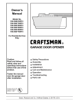
Owner's
Manual
Model No.
139.53661SRT3
139.53671SRT3
139.53672SRT3
139.53673SRT3
139.53674SRT2
139.53677SRT3
For Residential Use
Only
CRRFTSMRN®
GARAGE DOOR OPENER
Caution:
Read and follow all
safety rules and
operating instructions
before first use of this
product,
Fasten the manual
near the garage door
after installation.
Complies with UL 325
regulations effective
( U|
• Safety Precautions
• Assembly
• Installation
• Adjustment
• Care and Maintenance
• Operation
• Troubleshooting
• Parts List
)
January 1, 1993
Sears,
Roebuck
and Co., Hoffman Estates,
IL 60179 U.S.A.
Contents
Page
A review of safety alert symbols ................................. 2
You'll need tools.......................................................... 3
Safety information regarding garage door looks
and ropes .................................................................. 3
Testing your garage door for sticking, binding
and balance ............................................................... 3
Illustrationof sectional door installation ..................... 4
Illustration of one-piece door installation...................5
Carton inventory.......................................................... 6
Hardware inventory..................................................... 7
Contents
Page
Install the light and lens ................................................. 19
Attach emergency release rope and handle ................. 19
Electrical requiramemts ................................................. 20
Safety reversing sensor information.............................. 21
Install the safety reversing sensor........................... 22, 23
Fasten door bracket (sectional door) ............................ 24
Fasten door bracket (one-piece door) ........................... 25
Connect door arm to trolley (sectional door)................. 26
Connect door arm to trolley (one-piece door) ............... 27
Adjustment section - pages 28 - 30
Assembly section - pages 8 - 11
Assemble T-rail ......................................................... 8
Travel limitadjustments................................................. 28
Attach cable pulley bracket ....................................... 8
Install trolley .............................................................. 9
Test the safety reversing sensor ................................... 30
Fasten T-rail to opener ............................................. 9
Install chain/cable ................................................... 10
Attach sprocket cover ............................................. 10
Tighten the chain and cable ................................... 11
Installation section - pages 11 - 27
Installationsafety instructions................................. 11
Determine header bracket location
Sectional door ....................................................... 12
One-piece door ..................................................... 13
Install the header bracket ....................................... 14
Attach the T-rail to header bracket ......................... 15
Positionthe opener ................................................. 16
Hang the opener ..................................................... 17
Install the door control ............................................ 18
Force adjustments ......................................................... 29
Test the safety reverse system .................................... 30
Operation safety instructions........................................... 31
Care of your opener ......................................................... 31
Maintenance schedule .................................................... 31
Operation of your opener ................................................ 32
Receiver and remote control programming .................... 33
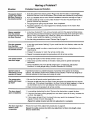
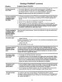
Having a problem? .................................................... 34, 35
Repair parts, rail assembly .............................................. 36
Repair parts, installation.................................................. 36
Repair parts, opener assembly ....................................... 37
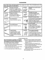
Accessories ...................................................................... 38
Index ................................................................................ 39
How to order repair parts ................................................. 40
Maintenance agreement .................................................. 40
Warranty .......................................................................... 40
Start by reviewing these important safety alert symbols
When you see these Safety Symbols on the following pages, they will alert you to the possibility of
serious injury or death if you do not comply with the corresponding instructions. The hazard may
come from something mechanical or from electric shock. Read the instructions carefully.
Mechanical
Electrical
When you see this Safety Symbol on the following pages, it will alert you to the possibility of damage
to your garage door and/or the garage door opener if you do not comply with the corresponding
instructions. Read the instructions carefully.
This garage door opener is designed and tested to offer safe service provided it is installed, operated,
maintained and tested in strict accordance with the safety instructions contained in this manual.
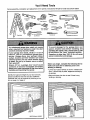
You'll Need Tools
During assembly, installation and adjustment of the opener, instructionswill call for hand tools shown below.
Pencil
OOQOIQQO o
Hack
.%
Saw
Tape Measure
Wire Cutters
3/16', 5/16
and
Claw Hammer
5/32" Drill Bits
Screwdriver
Stepladder
Adjustable
End Wrench
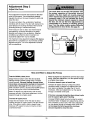
To avoid damage to the garage door and
opener, disable locks before installing and
operating the opener. Use a wood screw or nail
to hold locks in the "open" (unlocked) position.
An unbalanced garage door might not reverse
when required
and someone under the door
could be seriously injured or killed.
If your garage door binds, sticks or is out of
balance, call for professional
garage door
service. Garage doors, door springs, cables,
pulleys, brackets and their hardware are under
extreme tension and can cause serious injury
or death. Do not try to loosen, move or adjust
them yourself!
Ropes left on a garage door could cause
someone to become entangled
and killed.
Remove all ropes connected to the door before
installing and operating the opener.
Operation at other than 120V 60 Hz will cause
opener malfunction and damage.
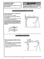
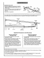
Before you begin, complete the following test to
make sure your door is balanced, and is not
sticking or binding:
• Lift the door about halfway as shown. Release the
door. It should stay in place, supported entirely by
its springs.
Identify the type and height of your door and any
special conditions that exist and any additional
materials that may be required by referring to the
lists on page 4 or page 5.
• Raise and lower the door to see if there is any
binding or sticking.
ONE-PIECE DOOR
3
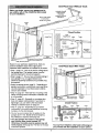
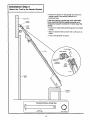
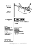
Before you begin, survey your garage area to
see whether any of the conditions below apply
to your installation.
Herizontal
FINISHED CEILING
Supporl bracket &
fastening hardware
is required.
See page 17.
and vertical reinforcement
is needed for lightweight garage doors
(fiberglass, steel, aluminum, door with glass panels, etc.).
See page 24 for details.
Slack in Chain Tension
is Normal When
Garage Door is Closed
Header Wall
Extension Spring
OR
;pring
AccessDoor
O
Safety
Reversing
Sensor
Floor must belevel
across width of door
Closed Position
• Safety Reversing Sensor
Head_er Cable
Bracket
Based on your particular requirements, there are
several installation steps which might call for
materials and/or hardware not included in the carton.
Garage
• Safety reversing sensor, page 21 - Depending
upon garage construction, wood blocks may need
to be fastened to mounting locations before
sensors are installed.
• Step 10, page 22 - Alternate floor mounting of the
safety reversing sensor will require hardware not
provided.
• Step 11, page 24 - Do you have a steel, aluminum,
fiberglass or glass panel door? If so, horizontat
and vertical reinforcement is required.
• Look at the garage door where it meets the floor.
It must close on the floor all the way across.
Other-wise, the safety reverse system may not
work properly, See page 30, Floor or door should
be repaired.
Trolle_
o
Door
• Step 1, page 12 - Look at the wall or ceiling above
the garage door. The header bracket mustbe
securely fastened to structural supports.
• Step 5, page 17 - Do you have a finished ceiling in
your garage? If so, a support bracket and
additional fastening hardware may be required.
Pulley
Brack_
Header
Garage
I
........
Rail Assembly
h
Emergel3cy
Release
Rope & Handle
Arm
boor
Bracket
• The opener can be installed within 2 feet of the left
or right of the door center if there is a torsion spring
or center bearing plate in the way of the header
bracket or door bracket area. If your door has
extension springs, the opener must be installed
in the center of the door See pages 12 and 24.
• Do you have an access door in addition to the
garage door? If not, Model 53702 Emergency
Key Release is required. See page 38.
• If your door is more than 7 feet high, see the rail
extension kits available on page 38.
You may find it helpful to refer back to this page as you proceed with the installation of your opener.
J__
--_
V_
One-Piece
Before you begin, survey your garage area to
see whether any of the conditions below apply
to your installation.
Door Without
FINlu_Ct_HEDbCr_Fd^L_N,G
&fastening
Track
_
_
_
hardware is required.
S_n
o h;intet_nSiOn
See psge 17.
garage door is closed.
Hewd/r
)l[F/_
_
I
Nt
0
_
Door Bracket
_v
J
J
II
r_ader
,.,_J]iI ._-_
.....
Gap between floor and bottom
of door must not exceed 1/4".
rs=ng
Sensor
Hope & Nandle
Door
_\Xl
Safety Reversing Sensor
Based on your particular requirements, there are
several installation steps which might call for
materials and/or hardware not included in the carton.
One-Piece
Door With Track
• Step 1, page 13 - Look at the wall or ceiling above
the garage door. The header bracket mustbe
securely fastened to structural supports.
• Step 5, page 17 - Do you have a finished ceiling in
your garage? If so, a support bracket and
additional fastening hardware (not provided) may
be required.
• Safety reversing sensor, page 21 - Depending on
garage construction, wood blocks may need to be
securely fastened to mounting locations before
sensors are installed.
• Step 10, page 22 - Alternate floor mounting of the
safety reversing sensor will require hardware that
is not provided.
• Step 11, page 25 - Generally, a one-piece door
does not require reinforcement. If your door is
lightweight, you can refer to the information
relating to sectional doors on page 24.
• Step 11, page 25 - Depending on your dooCs
construction, you might need additional mounting
hardware for the door bracket.
Safety
Reversing Sensor
Floor must be lever
across width of door
Sensor
Closed Position
Cable
t Bracket
Cable
Trolley
Chain
T-rail
• Do you have an access door in addition to the
garage door? If not, Model 53702 Emergency
Key Release is required. See page 38•
• The gap between the bottom of the garage
door and the floor cannot exceed 1/4".
Otherwise, the safety reverse system may not
work properly. See page 30. The floor or the door
should be repaired.
Garage Door
Bracket
Straight
Door
Arm
Release
Rope &Handle
You may find it helpful to refer back to this page as
you proceed with the installation of your opener,
5
Carton Inventory
Your garage door opener is packaged in two cartons which contain parts illustrated below. Accessories will
depend on model purchased. If anything is missing, carefully check the packing material. Parts may be "stuck"
in the foam. Hardware for assembly and installation is shown on page 7.
Models 53661 (1), 53671 (1), 53672 (2),
53673 (2), 53674 (2), 53677 (2)
Three-Function
Models 53661,
53671, 53672
Models 53673, 53674
Model 53677
Model 53674
Remote Control
with Visor Clip
Door Control Button
Standard
Premium
Control Console
Control Console
Security@
Keyless Entry
_
Cable
Pulley Bracket
Multi-Function
Light Lens
2-Conductor
Bell Wire
White & White/Red
T-Rail
End Sections
Door Bracket
End Sections
Sprocket Cover
"C" Wrap (2)
Header
Safety Reversing Sensor
Mounting Bracket
With Square Holes (2)
Bracket
J
Chain and Cable
in Dispensing Carton
Hanging Brackets
Curved Door
Arm Section
Safety Reversing Sensor
Mounting Bracket
With Slot (2)
Literature
SafetYandLabels
I
(2) Safety Reversing Sensors
(1 Sending Eye and t Receiving Eye)
with
2-Conductor White & White/Black Bell Wire
attached
Straight Door
Arm Section
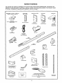
Separate all hardware from the packages in the rail carton and the opener carton,
shown below, for the assembly and installation procedures.
Assembly
Washered Screw
5/16"-18xl/2" (2)
(mounted in opener)
Hardware
Hex Screw
5/16"-16x7/8" (3)
Nut
5/16'-18
CarrLage Bolts
1/4"-20xl/2"
(4)
(5)
Master Link (2)
©
Trolley
Threaded Shaft (1)
©
Lock Washer
Lock Nut
5/16" (4)
Installation
1/4'-20x7/16"
(2)
Hex Screw
5/16"-18x7/6" (4)
Handle
©
Lag Screw
5/16"-18xl-7/8'
(4)
Hardware
_HIIIILHIIIIIILIID
5/16'-9x1-5/8"
as
Screw 6-32 x 1" (2)
©
Nut 5/16"-18 (6)
__._)
Lock Washer
Ring
Fastener (3)
(2)
Rail Grease
5/16" (6)
tlllllllltl!llltl
ItI ILIllllllll_
_ IIIIlillllllll!llltltLl=]_
Screw
6ABxt -1/4" (2)
Dry Wall Anchors (2)
Insulated
Staples (10)
[_
o]
[_
Clevis Pin
5/16"x2-3/4" (1)
oI
Clevis Pin
5/16"x1" (1)
Rope
o_
Clevis Pin
5/16"x1-1/4"
(1)
Safety Reversing Sensor
Installation Hardware
©
#14-10x1-1/2"
HH (4)
Carriage Bolts
1/4"-20xl/2"
(4)
Wing Nut (2)
©
_ll!lililllililiIHllLHilitl!!l_lll
Hex Screw
1/4-20xt-1/2"
(2)
Lock Nut
1/4"-20 (4}
Screw
#10 32x3/8"(4)
7
Lock Nut
#10x32 (4)
Insulated
Staples (20)
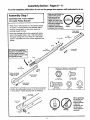
Assembly Section: Pages 8 - 11
To avoid installation
difficulties,
do not run the garage door opener until instructed to do so.
Make sure bolt necks are
seated tn the square
,_=
holes and rails are
aligned before you
tighten lock nuts.(See
right and wrong views).
Improper assembly can
cause jerky trolley
operation,noise and/or
Right
nuisance door reversals.
Assembly Step 1
Assemble
the T-rail & Attach
the Cable Pulley Bracket
• Align the 3 T-rail sections on a flat surface exactly
as shown. The end sections are identical. Make
sure the "arrow label" on the center section is
pointing toward the door.
• Insert the carriage
seat in the square
and pass through
section. Assemble
tighten.
Wrong
T-RAIL BACK
(TO OPENER)
bolts so the square bolt necks
holes in the T-rail end sections
the round holes in T-rail center
lock nuts, ensure alignment and
T-rail
(End Section)
1/4" Lock Nut
Brace
T-rail
(Center Section)
If T-rail is not assembled
EXACTLY as shown, trolley
will not travel smoothly
along length of rail or it will
hit against the nuts.
Carriage Bolt
,
"_f
1/4"-20xl/2"
Brace
T-rail
(End Section)
Hardware Shown Actual Size
Cable pulley bracket
attaches to FRONT
END of T-rail
©
Square Carriage
Bolt Holes
Lock Nut
1/4" o20 x 7/16"
©©
T-RAIL FRONT
(TO DOOR)
Nut
5/16" - 18
Hex Screw
5/16" - 18 x7/6'
Position the cable pulley bracket on the front end of the
T-rail as shown. Fasten securely with the hardware,
Rex
Carriage Bolts
1/4" - 20 x 1/2"
Lock Washer
5/16"
Screws
5/16'-18x7/8"
Cable
Pulley
Bracket
(
_£\o_,e6
When tightening
b
Ri, ht
Lock Washer
5/16"
Nut
5/16"
8
Q
Wrong
sure to keep
bracket parallel
to the rail
Otherwise, the
thescrews'be
rail may bow
when opener is
operated.
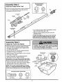
Assembly
Hardware Shown
Actual Size
Step 2
Install the Trolley
on the T-rail
©©
• Attach the threaded shaft to the trolley with the
lock washer and nuts as shown.
Lock Washer
5/16"
Trolley
Nut
5/16" - 18
Lock Washer
5/16'
Outer Nut
Inner Nut
5/16"
Trolley
Threaded
Shaft
Trolley
Temporary Stop
Screwdriver
• As a temporary stop, insert a screwdriver
hole in the front end of the T-rail.
into the
• Slide the trolley assembly along the rail to the
screwdriver stop.
If trolley hits against any nuts on the T-rail, the
bolts and nuts were attached from the wrong
side and must be repositioned. Review Step 1.
Assembly
Step 3
I
I
Fasten the T-raft to the Opener
• Place the opener on packing material to protect
the cover. For convenience, put a support under
the cable pulley bracket.
• Remove the (2) 5/16"-18xl/2" washered screws
mounted in the top of the opener.
Washered
• Align the holes in the back section of the T-rail with
the holes in the opener.
• Fasten the rail with the (2) washered screws
previously removed. Tighten securely.
Remember to use only these screws./Any other
screws will cause serious damage to the opener.
• Insert a 5/16"-1 8x7/8" hex screw into the cover
protection bolt hole in the T-rail as shown. Tighten
securely with a 5/16" lock washer and nut.
NOTE: This screw prevents trolley over-travel.
Keep a 2" minimum between the trolley and this
screw when adjusting travel limits (see page 28).
Hardware Shown Actual Size
l'l'l'l'l'lll'llL'llD
Hex Screw
5/16' - 18 x 7/8"
Nut
5/16"- 18
Lock Washer
5/16'
Screw
5/16"-18xl/2"
5/16 °- 18x7/8"
Cover
Protection
Bo_ Hole
Lock Washer
5/16"
Assembly
Step 4
Install the Chain/Cable
&
Attach the Sprocket Cover
Dispensing
Cadon
Figure 2
Leave Chain and Cable
Opener
Sprocket
Inside Dispensing
Carton to Prevent Kinking.
Keep Chain and Cable
Taut When DLspensing
• Detach the cable loop from the carton and fasten it
to the trolley with a master link from the hardware
bag. See master link procedure, Figure 1.
Figure 3
I • With the trolley against the screwdriver, dispense
the cable around the pulley.
Proceed back around the opener sprocket,
Figure 2. Be sure sprocket teeth engage the
chain. Continue forward to the trolley
threaded shaft, Figure 3.
Use the second master link to connect
the chain to the flat end of the shaft.
Cheek to make sure the chain is
not twisted.
Master Link
Clip-On Spring
Ma_er
Link Cap
Master Link
Flat End
of Trol_y
ThreadedShaff
Chain
Remove the screwdriver.
T-rail
t
•Pin Notch
'Pin
Trolley
_
Ma_ter
Link Bar
Figure
Cable
Pulley
1
Master Link Procedure:
Install Chain and Cable
In This Direction
Push pins of master link bar
through cable loop and hole in
front end of trolley. Push cap
over pins and past notches.
Slide clip-on spdng over cap
and into notches until both
pins are securely locked.
Sprocket
Cover
Back Tab Slot
Top of Opener
To attach the sprocket cover:
Front Tab Slot
• Insert the back tab in the opener slot. Squeeze the
cover slightly and insert the front tab in the slot on
the mounting plate.
Mounting
Plate
_J
10
Assembly
I
Step 5
Tighten the Chain & Cable
Lock
Washer
Outer Nut
• Spin the inner nut and lock washer down the
threaded shaft, away from the trolley.
To Tighten Outer Nut _,._-'_
To tighten the chain, turn outer nut in the direction
shown. As you turn the nut, keep the chain
from twisting.
I_
When the chain is approximately 1/2" above the
base of the T-rail at its midpoint, re-tighten the
inner nut to secure the adjustment.
r _
warnings
before
proceeding
_
/
"*-'--
ToTighten
_
Chain
I
II
II
II
II
II
I_
I_
II
II
II
1/2 Inch
Base of T-rail
NOTE: During future maintenance, ALWAYS
pull the emergency release handle to disconnect
trolley before adjusting chain.
assembling
_
\
Inner Nut
Trolley
is complete, you may notice some
the door closed. This is normal. If
to the position shown when the
not re-adjust the chain.
You have now finished
_
_
Sprocket noise can result if chain is either too
loose or too tight.
When installation
chain droop with
the chain returns
door is open, do
Inner Nut
your garage
to the installation
door opener. Please read the following
section:
IMPORTANT INSTALLATION INSTRUCTIONS
To reduce the risk of severe injury or death to persons:
1. READ AND FOLLOW
ALL INSTALLATION
INSTRUCTIONS.
2. Install only on a properly balanced and lubricated garage door. An improperly balanced door
may not reverse and could resuff in severe injury or death. Repairs to cables, spring assemblies
and other hardware must be made by a professional service person before installing opener.
3. Disable all locks and remove all ropes connected to the garage door before installing the opener.
Ropes connected to a garage door can cause entanglement and death.
4. If possible, install door opener 7 feet or more above floor with the emergency release handle
mounted 6 feet above the floor.
5. Do not connect the opener to power source until instructed to do so.
6. Locate the Door Control within sight of the door at a minimum height of 5 feet where small
children cannot reach and away from all moving parts of the door.
7. Install the User Safety Instruction Label on the wall adjacent to the door control and the
Maintenance Instruction Label in a prominent location on the inside of the garage door.
8. Upon completion of the installation, the door must reverse when it comes in contact with a
one-inch high object or a 2x4 laid flat on the floor.
9. Do not wear watches, rings or loose clothing while installing or servicing an opener. Jewelry or
loose clothing can be caught in the mechanism of the garage door or the opener.
11
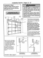
Installation
Installation
Determine
Section:
Pages 12 - 27
Step 1
Header
Bracket
Location
If the header bracket is not rigidly fastened to
a structural
support on the header wall or
ceiling, the safety reverse system may not
work properly (see page 30), The door might
not reverse when required, and could cause
serious injury or death.
Installation procedures vary according to
garage door types. Follow the instructions
which apply to your door.
__ Header
Wall
The garage door springs, cables, pulleys,
brackets and their hardware are under extreme
tension. Do not attempt to loosen, move or
adjust them yourself. Serious personal injury
or death could result. Call for professional
garage door service.
__ Finished
Ceiling
vergc_{I
Guideline
2x4
St_ctural
ods
jJ
/
• Close the door and mark the inside
vertical centerline of the garage door.
• Extend the line onto the header wall
above the door.
Remember, you can fasten the
header bracket within 2 feet of the
left or right of the door center onlyif
a torsion spring or center bearing
plate is in the way; or you can attach
it to the ceiling (refer to page 14)
when clearance is minimal. (It may
be mounted on the wall upside down
if necessary, to gain approximately
1/2".)
If you need to install the header bracket
on a 2x4 (on wail or ceiling), use lag
screws (not provided) to securely fasten
the 2x4 to structural supports as shown
here and on page 13.
Ceiling
Header
• Open your door to the highest
point of travel as shown. Draw
an intersecting horizontal line
on the header wall 2" above
the high point. This height will
provide travel clearance for the
top edge of the door.
Door clearance brackets are
available for sectional doors
when headroom clearance is
less than 2". See accessory
page 38.
-
_
.
Header
Track
Highest Point
of Travel
Highest Point
of Travel
Door
Sectional door
with curved track
Proceed
Track
to Step 2, page 14.
12
One-piece door
with horizontal track
Read the Safety instructions
on page 12. They also apply to doors without
tracks.
Infinished Header Wall
Vertical
Centerline
2x4
• Close the door and mark the
inside vertical centerline of
your garage door. Extend the
line onto the header wall
above door.
If headroom clearance is
minimal, you can install the
header bracket on the ceiling.
See page 14.
OPTIONAL CEILING MOUNT
FOR HEADER BRACKET
• If you need to install the
header bracket on a 2x4 (on
wall or ceiling), use lag screws
(not provided) to securely
fasten the 2x4 to structural
supports as shown.
Header Wall
Highest Point
of Travel
/
Door
1
71'
y:
One-piece door without track
pivot hardware
One-piece door without track
jamb hardware
• Open your door to the highest
shown. Measure the distance
door to the floor. Subtract the
door. Add 8" to the remainder.
EXAMPLE
point of travel as
from the top of the
actual height of the
(See Example).
Distance from top of door
(at highest point of travel) to floor ........................... 92"
Actual he'ght of door ............................................. -88'
Rema'nder ................................................................
4'
• Close the door and draw an intersecting horizontal
line on the header wall at the determined height.
If the total number of inches exceeds the height
available in your garage, use the maximum
height possible, or refer to page 14 for ceiling
installation.
Proceed
Add .........................................................................
+8"
Bracket height on header wall ...............................
12"
(Measure UP from top of CLOSED door.)
to Step 2, page 14.
13
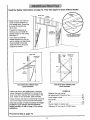
Installation
Install
You can attach the header bracket either to the
wall above the garage door, or to the ceiling.
Follow the instructions which will work best for
your particular requirements,
Step 2
the Header
Bracket
Fasten the Header
Bracket
to the Wall
• Mark either set of bracket holes (do not use the
holes designated for ceiling mount). Drill 3/16" pilot
holes and fasten the bracket securely to a structural
support with the hardware provided.
• Center the bracket on the vertical guideline with
the bottom edge of the bracket on the horizontal
line as shown (with the arrow pointing toward the
ceiling).
Wall
Mounting Holes
__ Header
Wall
_
s
Lag Screws
5/16"x9x1-5/8"
2x4
Structural
Supped
Door
Spnng
The nail hole is for positioning
only. You must use lag screws to
mount the header bracket.
Optional
Wall Mounting
Holes
s
s
Hardware Shown Actual Size
Door
Highest
Point of Travel
(of Garage Door)
Vertical
Center
Line
_l
II'll!lg[Sclr!lw
5/16'-9xl
Fasten the Header Bracket
1'111111_
-5/8'
to the Ceiling
Extend the vertical guideline onto the ceiling as
shown.
• Center the bracket on the vertical mark, no more
than 6" from the wall. Make sure the arrow is
pointing toward the wall. The bracket can be
mounted flush against the ceiling when clearance
is minimal.
• Mark holes designated for ceiling mount only. Drill
3/16" pilot holes and fasten bracket securely to a
structural support with the hardware provided.
Door
Ceiling Mounting
Holes
Spdng
Wall
The nail hole is for positioning only,
You must use lag screws to mount
the header bracket.
14
Attach
the T-rail Step
to the 3Header
Installation
Bracket
[
• Position the opener on the garage floor below the
header bracket. Use packing material as a
protective base.
If the door spring is in the way you'll need help.
Have someone hold the opener securely on a
temporary support to allow the T-rail to clear the
spring,
Header
Sracket
Cable
• Position the cable pulley bracket against the header
bracket,
Bracket
• Align the bracket holes and join with a clevis pin as
shown.
• Insert a ring fastener to secure.
Ring Fastener
Header Bracket
Clevis Pin
5/16"x2-3/4"
Cable
Pulley "
Bracket
Temporary
Support
Hardware Shown Actual Size
o]
Clevis
5/16"
Pin
x 2-3/4"
©
Ring Fastener
15
Installation
Position
Step 4
the Opener
Follow instructions
type as illustrated.
which apply to your door
A 2x4 laid flat is convenient for setting an ideal
door-to-T-rail distance.
T rail
• Raise the opener onto a stepladder.
2x4
You will need help at this point if the ladder is
not tall enough.
• Open the door all the way and place a 2x4 laid flat
on the top section beneath the T-rail,
Door
If the top panel hits the trolley when you raise
the door, pull down on the trolley release arm to
disconnect the inner and outer sections. The
trolley can remain disconnected until Step 12 is
completed,
Header
• With the door fully open and parallel to the floor,
measure the distance from the floor to the top of
the door.
Top of Opener
I
• Using a stepladder as a support, raise the opener
to the same distance as the door from the floor (it
will be at a slight angle as shown).
The top of the door should be level with the top of
the opener. Do not position the opener more than
2" above this point.
Stepladder
16
Installation
Step 5
Hang the Opener
Two representative installations are shown.
Yours may be different. Hanging brackets should
be angled, Figure 1, to provide rigid support. On
finished ceilings, Figure 2, attach a sturdy metal
bracket to structural supports before instattingthe
opener. The bracket and fastening hardware are not
_rovided. See accessory page 38.
Figure I
Supports
• Measure the distance from each side of the opener
to the structural support.
• Cut both pieces of the hanging bracket to required
lengths.
Screws
5/16"- 18xl -7/8"
Measur8
Distance
• Drill 3/16" pilot holes in the structural supports.
• Attach one end of each bracket to a support with
5/16"-18xl -7/8" lag screws.
\\
• Fasten the opener to the hanging brackets with
5/16"-18x7/8" screws, lock washers and nuts.
• Check to make sure the T-rail is centered over the
door (or in line with the header bracket if the
bracket is not centered above the door).
5/16"- 18x7/8" Screw
5/16" Lock Washer
5/16"-18 Nut
Remove the 2x4. Operate the door manually. If the
door hits the rail, raise the header bracket.
Figure 2
Hidden
Support /
Grease the top and
underside of the rail
surface where the trolley
slides. A tube of grease
_ _-_ _ _
f
-7/8"
,llllLIllllllllllLILID
Nut 5/16"-18
i_
©
Lock Washer 5/16 =
17
_
I
_ _ _
--
_"
FINISHED CEILING
5/16"-18xl -7/8" I
0 0
_
--
Lag Screws
_
Hardware Shown Actual Size
Hex Screw
5/16" 18x7/8"
_
- _
Support B
No provded
511 6"18xl
_
"
_-_-_
_ _ _
"
- "(Not
Provided)
5/16-18x7/8
Screw
Installation
Install the Door Step
Control 6
I
Do not connect to live electrical w/ring. Connect
only to 24 Volt low voltage wires. Connection to
live wires or higher voltage may cause serious
injury from shock, burn or electrocution.
Children operating or playing with a garage
door opener can injure themselves or others.
The garage door could close and cause
serious injury or death.
Install the door control (or any additional push
buttons) out of the reach of children and away
from all moving parts of the door and door
hardware, but where the garage door is visible.
Do not allow children to operate the push
button(s) or the remote control(s).
A moving garage door could injure someone
under it. Activate the opener only when the
door is properly adjusted, you can see it clearly,
and there are no obstructions to door travel.
Locate the door control within sight of the door
at a minimum height of 5 feet where small
children cannot reach, and away from all moving
parts of the door and door hardware,
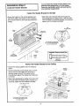
The door control is typically attached directly to the
wall. If installing into drywall, drill 5/32" holes and
use the anchors provided. For pre-wired installations
(as in new home construction), Console models
may be mounted to a standard single gang box
(FixTure2).
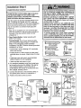
1. Strip 1/4" of insulation from one end of the bell
wire and connect it to the two screw terminals on
the back of the door control: white to 2 and
white/red to 1.
2. Door Control Button: Fasten securely with
6ABx 1- 1/2" screws.
Console Model: Pry off cover along one side
with a screwdriver blade (Figure 1). Fasten with
6ABx1-1/4" self-tapping screws (standard
installation) or 6-32xl" machine screws (pre-wired
installation) as follows:
Hardware Shown
Actual Size
_] IIill_llllll!=ll!=lll=lllllllll_
6AB x 1-1/2" Screw
Door Control Button
• Install bottom screw, allowing 1/8" to protrude
above walt surface.
6AB x 1-1/4' Screw
tll_llllllllllllllllllll_
Control Console (std installation)
• Position bottom of door control on screw head
and slide down to secure. Adjust screw for snug
fit.
Insulated
Staples
Control Console (pre-wired)
• Install top screw with care to avoid cracking
plastic housing. Do not overtighten.
Figure 1
• insert top tabs and snap on cover.
REMOVE & REPLACE COVER
To Replace,
insert
Top Tabs
. "
3. (For standard installation only) Run the bell wire
up the wall and across the ceiling to the opener.
Use insulated staples to secure the wire in
several places. Be careful not to pierce the wire
with a staple, creating a short.
4. Connect the bell wire to the terminal screws on
the opener panel: white to 2; white/red to 1.
5. Position the antenna wire as shown.
First
_ *"
Dry Wall Anchors
Figure
2
PRE-WlRED
INSTALLATION
To Remove,
Twist
Here
.-
24 Volt
2-Conductor
Bell Wire
STANDARD CONTROL
(BACK VIEW)
Mounting
- Hole
DOOR CONTROL
Bu'n'ON
(BACK)
Lighted
Push Button
Top
Terminal
Screws
_#
Bottom
Bell
Wire
,Jl
_
"Mounting
Hole
PREMIUM CONTROL
(BACK VIEW)
Top
Mounting
'-_--_
- Hole
Bell
Wire
i Terminal Screws
DOOR
CONTROL
BUTTON
STANDARD
CONTROL
CONSOLE
PREMIUM
CONTROL
CONSOLE
_t_
Back Panel
of Opener
Terminal
....
Bw_ _
.
18
_
Bottom
Mounting
>Screws
" Hole
6.AttachtheUserSafetyInstruction
labeltothewall
nearthedoorcontrol,andthe Maintenance
Instructionlabelin a prominentlocationonthe
insideofthegaragedoor.
Do NOT connect the power and operate the
opener at this time. The trolley will travel to the
full open position but will not return to the
close position
until the sensor
beam is
connected and properly aligned.
See Safety Reversing
Sensor instructions
beginning on page 21.
Page 32 explains how to use the door control.
Installation
Install
Install
Step 7
the Light and the Lens
the
lights
• Install a 75 watt maximum light bulb in the socket.
The light will turn ON and remain lit for
approximately 4-1/2 minutes when power is
connected. Then the light will turn OFF.
Lens Guide
If the bulb burns out prematurely due to vibration,
replace it with a standard neck "Garage Door
Opener" bulb.
Ught
nstall the lens
• Apply slight pressure on the sides of the lens and
slide the tabs into the slots in the end panel.
75 Watt Max.
Light Bulb
• Reverse the procedure to remove the lens.
Installation
Step 8
Attach the Emergency
Release Rope and Handle
Do not use the red handle to pull the door open
or closed. The rope knot could become untied
andyou could fail Use the emergency release
only to disengage the trolley and, if possible,
only when the door is closed.
Garage doors are heavy. If the door is open
when the handle is pulled, the door could close
inadvertently
if it is not properly balanced.
Serious injury may result to persons under the
door. Make sure the doorway
is clear of
persons and obstructions before pulling handle
when door is open.
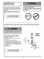
• Thread one end of the rope through the hole in
the top of the red handle so "NOTICE" reads right
side up as shown. Secure with an overhand knot.
The knot should be at least 1" from the end of
the rope to prevent slipping.
• Thread the other end of the rope through the hole
in the release arm of the outer trolley.
• Adjust rope length so the handle is 6 feet above
the floor. Secure with an overhand knot.
If it is necessary to cut the rope, heat seal the
cut end with a match or lighter to prevent
unraveling.
Knot
%_
OVerhand
Trolley
Releas
e Arm
Rope
Release Handle
Kn°t
19
_
Installation
Electrical
Step 9
Requirements
To prevent electrocution
or fire, installation
and wiring must be in compliance with local
electrical and building codes.
To reduce the risk of electric shock, your garage
door opener has a grounding type plug with a third
grounding pin. This plug will onlyfit into a grounding
type outlet.
Do NOTuse an extension cord, 2-wire adapter,
or change the plug in any way to make it fit
i your outlet.
if the plug doesn't fit into the outlet you have,
contact a qualified electrician to install the proper
outlet.
To avoid installation difficulties,
do not run the opener at this time.
I
I
I
Right
If permanent
wiring
is required
Wrong
by your local code, refer to the following
procedure:
Permanent
Wiring
Connections
To make a permanent connection through the
7/8" diameter hole in the top of the opener
(according to local code):
Ground Tab
• Remove the opener cover screws and set the
cover aside.
\
Green
Ground_
• Remove the attached 3-prong cord.
Screw
• Connect the black (line) wire to the screw on the
brass terminal; the white (neutral) wire to the
screw on the silver terminal; and the ground wire
to the green ground screw. The opener must be
grounded.
• Reinstallthe cover.
Ground
Wire
Black
Wire
Wh_eWire
Wire
I
doTonot
avoid
run installation
the opener difficulties,
at this time.
2O
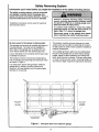
Safety Reversing System
Information
you'll
need
before
you begin
the installation
and aligned correctly before the garage door
The
safety
sensor
connected
opener
will reversing
move in the
down mustbe
direction.
This is a
required safety device and cannot be disabled.
Installation procedures
and one-piece doors.
of the safety
reversing
sensor,
Without a properly
working safety reversing
sensor, persons (particularly children) could
be injured or killed by a closing garage door.
Read and follow all instructions.
are the same for sectional
To protect small children, install the safety
reversing sensor so that the beam will be no
higher than 4"-6" above the garage floor.
Disconnect power to the garage door opener
before installing the safety reversing sensor.
Be sure power to the opener is disconnected,
The brackets mustbe securely fastened to a solid
surface such as the studs on either side of the door,
or add a piece of wood at each location if installing in
masonry construction.
The sending eye transmits an invisible light beam to
the receiving eye. The units can be installed on
either side of the garage door as long as the sun
never shines directly into the receiving eye lens.
The invisible light beam path must be unobstructed.
No part of the garage door (or door tracks, springs,
hinges, rollers or other hardware) can interrupt the
beam while the door is closing. If it does, use a piece
of wood to build out each sensor mounting location to
the minimum depth required for light beam clearance.
Look at the label on the connector end of each case
to identify the sensors.
The brackets must be connected and fastened so
that the sending and receiving eyes face each other
as shown in Figure 1.
If an obstruction breaks the light beam while the
garage door is closing, the door will stop and
reverse to full open position and the opener lights
will flash for 5 seconds.
I LLIvI
1
Figure 1: Facing the door from inside the garage
21
Installation
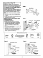
Step 10
I
Install the Safety Reversing
I
Sensor
Figure 2
Figures 2 and 3 show assembly of brackets and
"C" wrap based on the recommended installation of
the sensors as shown on page 21.
Mounting Bracket
With Square Holes
However, Figures 4 and 5 are variations which may
fit your installation requirements better. Make sure
the wraps and brackets are aligned so the
sensors will face each other across the garage
door.
"C" Wrap
#10-32
Lock Nuts
• Fasten the "C" wraps to the mounting brackets
having square holes, using the hardware shown
in Figure 2.
#10-32;<3/8"
Screws
• Connect each assembly to a slotted bracket, using
the hardware shown in Figure 3.
Note the alignment of the brackets
right sides of the door.
Figure 3
for left and
#14-10x1-1/2"
• Finger tighten the lock nuts,
HH
1/4-20xl/2" CarriageBolls
(withsquareshoulder)
• Use bracket mounting holes as a template to
locate and drill (2) 3/16" diameter pilot holes on
both sides of the garage door, 4"-6" above the
floor but not exceeding 6". (See warning on
page 21 .)
• Attach bracket assemblies with #14-10x1-1/2" lag
screws as shown in Figure 3.
• Adjust right and left side bracket assemblies to the
same distance out from the mounting surface.
Make sure all door hardware obstructions are
cleared. Tighten the nuts securely.
"C" Wrap
Mounting Bracket
with Square Holes
Hardware Shown Actual Size
©
,,..o
©
#10-32x3/8"
Screw
#10x32
Lock Nut
Lag Screw
Staples
Figure 4
Carr_,ge
Boits
Lock Nut
Figure 5
Alternate Wall Mount
Alternate Floor Mount
iiiiiii_iiii_iiiiii_iii
_i
i
::::::::::::::::::
::::::::::_::::::::::
::::::::::::::::::::
Mounting Bracket
with Slot
Sensor with wire
Indicator Light
Mounting Bracket
Mounting Bracket
with Square Holes
Mounting Bracket
• with Slot
Attach with
concrete anchors
with wire
Indicator Light
22
• Centereachsensorunitin a "C"wrapwithlenses
pointingtowardeachotheracrossthedoor(see
Figure6).
Securesensorswiththehardwareshown.Finger
tightenthewingnutonthereceiving eye to allow
Figure 6
Indicator
Light
for final adjustment. Securely tighten the sending
eye wing nut.
1/4-20 x 1-1/2"
Hex Soft
Run the wires from both sensors to the opener.
Use insulated staples to secure wire to wall and
ceiling.
Trouble
• Strip 1/4" of insulation from each set of wires.
Separate white and white/black wires sufficiently to
connect to the opener terminal screws: white to 2
and white/black to 3.
Shooting
1. If the sending eye indicator light does not glow
steadilyafter installation, check for:
• Electric power to the opener.
• A short in the white or white/black wires. These
can occur under staples or at screw terminal
connections.
Aligning the Safety Sensors
• Plug in the opener. Green indicator lights in both
the sending and receiving eyes will g/oweteadi/yif
wiring connections and alignment are correct.
• Incorrect wiring between sensors and opener.
• An open wire (wire break).
The sending eye indicator light will glow regardless
of alignment or obstruction. If the indicator light is
off, dim or flickering in the receiving eye (and the
invisible light beam path is not obstructed),
alignment is required.
2. If the sending eye indicator light glows steadilybut
the receiving eye indicator light doesn't:
• Check alignment.
• Check for an open wire to the receiving eye.
3. If the receiving eye indicator light is dim, realign
either sensor.
• Loosen the sendingeye wing nut and re-adjust,
aiming directly at the receiving eye. Lock in place.
NOTE: When the invisible beam path is obstructed or
misaligned while the door is closing, the door will
reverse. If the door is already open, ff will not close.
The opener lights will flash 10 times. (If bulbs are not
installed, 10 clicks are audible.,) See page 21.
• Loosen the receivingeye wing nut and adjust
sensor vertically and/or horizontally until it receives
the sender's beam. When the green indicator light
glows steadily, tighten the wing nut.
Figure 7
Connect
Opener
Wire
to
Terrninals
Bell Wire
._.~..
_B.BellWire
Sensor
Door Control
Conne_ions_
(dotted line)
,'-
CoNnections
J
[]
OPENER TERMtNAL
Sensor
\
Sensor
Invisible Light Beam
Protecgon Area
23
SCREWS
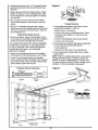
Installation
Step 11
Fasten Door Bracket
Follow instructions which apply to your door
type as illustrated below or on page 25.
A horizontal brace should be long enough to be secured to 2 vertical supports. A vertical brace should
cover the height of the top panel.
The illustration shows one piece of angle iron as the horizontal brace. For the vertical brace, 2 pieces of
angle iron are used to create a "U"-shaped support. The best solution is to check with your garage door
manufacturer for an opener installation door reinforcement kit.
Header
Bracket
Horizontal and vedical reinforcement
is needed for lightweight garage doors
(fiberglass, aluminum, steel, doors
with glass panel, etc). (Not Provided)
Figure 1
Reinforcement
Guideline
Door
Bracket
Location
;/
I
_
Carriage Bolt
5/16"-18x2-1/2"
UP
Door
Bracket
Washer
5/16'
Nut
5/16"-18
_ns_e
Edge
Figure 2
of Door or
inforcement Board
uP
• Center the door bracket on the previously marked
vertical guideline used for the header bracket
installation. Note the correct UP placement, as
stamped inside the bracket.
Door
• Position the bracket on the face of the door within
the following limits:
A) The top edge of the bracket 2"-4" below the top
edge of the door.
Brooke
Hardware Shown Actual Size
©
B) The top edge of the bracket directly below any
structural support across the top of the door.
Nut 5/16" - t8
• Mark and drill 5/16" left and right fastening holes.
Secure the bracket as shown in Figure 1 if there is
vertical reinforcement.
©
LockWasher
IIIIIllllltlllllll
Carriage Bolt
If your installation doesn't require vertical reinforcement but does need top and bottom fastening holes
for the door bracket, fasten as shown in Figure 2.
5/16" 18 x 2-1/2"
24
5/16"
Please read and comply with the warnings
They apply to one-piece doors also.
Header Wall
-- Finished
and reinforcement
instructions
on page 24.
Ceiling --
2x4 Support
Header
Bracket
Bracket
Horizontal and vertical
reinforcement is needed for
Placement
of Door
Bracket
lightweight garage doors
(fiberglass, aluminum, steel,
door with glass panel, etc.).
(Not Provided)
®
Vertical
;entedlne of
Garage Door
Nut _
5/16"-'_8
Door
I_
i
I
I
-
5/16'
Top of Door
(Inside Garage)
I
J
of Door
Top
Edge
___
--
!
_
For a door with no
the optional installation,
exposed
framing
use 5/16"xl
-1/2" orfor
lag
screws (not provided)
_
i
_=
[
Optional
Placement
Carriage Bolt
5/16"-18x2-1/2"
• Center the bracket on the top of the door, in line
with the header bracket as shown. Mark holes.
Hardware Shown Actual Size
• Drill 5/16" pilot holes and fasten the door bracket
with hardware supplied.
©
If the door has no exposed framing, drill 3/16" pilot
holes and fasten the bracket with 5/16"xl-1/2" lag
screws (not provided) to the top of the door.
The door bracket may be installed on the top
edge of the door if required for your installation,
(Refer to the dotted line optional placement
drawing,) Drill 3/16" pilot holes and substitute
5/16"x1-1/2" lag screws (not provided) to fasten
the bracket to the door.
©
lll!lll!lllllllllllllll!!ll
I!11111
Nut 5/16"-
18
Lock Washer
Carriage Bolt
5/16"-18 x 2-112"
25
5/16'
Installation
Connect
Step 12
Door Arm to Trolley
Follow instructions which apply to your door
type as illustrated below and on page 27.
Make sure garage door is fully closed. Pull the emergency release handle to disconnect the outer trolley
from the inner trolley. Slide the outer trolley back (away from the door) about 2" as shown in
Figures 1, 2 and 3.
Figure 1 :
Figure 2:
• Fasten straight door arm section to outer trolley
with the 5/16"xl" clevis pin. Secure the connection
with a ring fastener.
• Fasten curved door arm to the door bracket in the
same way, using the 5/16"xl- 1/4" clevis pin.
• Bring arm sections together. Find two pairs of holes
that line up and join sections. Select holes as far
apart as possible to increase door arm rigidity.
Inner TroLley
Lock
Washers
5/16"
;levis Pin
5/16"x 1•
Rope
Emergency
Release
Handle
Nuts
5/16 - 18
Door Arm
;urved
Door Arm
Clevis Pin
5/16"x1-1/4'
I
Figure I
Door Bracket
Figure
2
Figure
3
Hole Alignment Alternative
Figure 3:
if holes in curved arm are above holes in straight
arm, disconnect straight arm. Cut about 6" from
the solid end. Reconnect to trolley with cutend
down as shown.
Lock
Washers
5116"
Bring arm sections together.
• Find two pairs of holes that line up and join with
screws, lock washers and nuts.
5/16"-18
Hardware
Shown Actual Size
Nuts
@ ©0
Nut
5116" - 18
5/16"x
Lock Washer
1" (Trolley)
5/16"xl
5/16 =
Screws
_O/
Ring Fastener
1/4" (Doorgracket)
" Cut This End
Hex Screw
5/16"- 1B x 7/8"
Proceed to Adjustment Step 1, page 28. Trolley will re-engage automatically when the opener is operated.
26
Assemble the Door Arm:
• Fasten the straight and curved door arm sections
together to the longest possible length (with a 2 or
3 hole overlap).
Door
Ring
Washers
_5/16e"rs
_Lock
5/16"
Brack_
• With the door closed, connect the straight door arm
section to the door bracket with the 5/16"xl-1/4"
clevis pin.
C{evis Pin
Straight
_----_'_"
Screws
• Secure with a ring fastener.
5/16"-1g
Nuts
}
I / \/I
_""
6116"-1 8x7/8 ,F_
rved
Door Arm
On one-piece doors, before connecting the door arm to the trolley the travel limits must be adjusted. Limit adjustment
screws are located on the left side panel as shown on page 28. Follow adjustment procedures below.
Fully Closed
Trolley
Fully Open
Trolley
Door Arm
Connector Hole
I
,
'
..................................
1
I
iI
i
Closed
Door
Open Door
Adjustment
j._r__.:
Door Arm
Door with
Backward Slant
Procedures
Open Door Adjustment:
Decrease UP limit
for One-Piece
Doors
Closed Door Adjustment:
Decrease DOWN limit
• Turn the UP limit adjustment screw counterclockwise 5-1/2 turns.
• Turn the DOWN limit adjustment screw clockwise 5
complete turns.
• Press the Door Control push bar or button. The
trolley will travel to the fully open position.
• Press the Door Control push bar or button. The
trolley will travel to the fully closed position.
• Manually raise the door to the open position
(parallel to the floor), and lift the door arm to the
trolley. The arm should touch the trolley just in
back of the door arm connector hole. Refer to the
fully open trolley/door arm positions in the
illustration. If the arm does not extend far enough,
adjust the limit further. One full turn equals 2" of
trolley travel.
• Manually close the door and lift the door arm to the
trolley. The arm should touch the trolley just ahead
of the door arm connector hole. Refer to the fully
closed trolley/door arm positions in the illustration. If
the arm is behind the connector hole, adjust the limit
further. One full turn equals 2" of trolley travel.
Connect the door arm to the trolley.
• Close the door and join the curved arm to the connector hole in the trolley with the remaining clevis pin. It may
be necessary to lift the door slightly to make the connection.
• Secure with a ring fastener.
• Run the opener through a complete travel cycle. If the door has a slight "backward" slant in full open position
as shown in the illustration, decrease the UP limit until the door is parallel to the floor.
27
Adjustment Section: Pages 28 - 30
Adjustment
Adjust
Step 1
the UP and DOWN
Limits
Do not make any limit adjustments until the
safety reversing sensors are completely
installed.
Limit adjustment settings regulate the points at
which the door will stopwhen moving up or down.
The door will stop in the up direction if anything
interferes with door travel. The door will reverse in
the down direction if anything interferes with the
door travel (including binding or unbalanced doors).
To operate the opener, press the Door Control push
button. Run the opener through a complete travel
cycle.
Limit
Adjustment
Screws
• Does the door open and close completely?
• Does the door stay closed and not reverse
unintentionally when fully closed?
If your door passes both of these tests, no limit
adjustments are necessary unless the reversing test
fails (See page 30).
Cover /
Protection
Bolt
Left Side Panel
Adjustment procedures are outlined below. Run the
opener through a complete travel cycle after
each adjustment.
Repeated operation of the opener during adjustment
orocedures may cause the motor to overheat and
shut off. Simply wait 15 minutes and try again.
Adjustment
Read the procedures carefully before continuing on
to Adjustment Step 2. Use a screwdriver to make
limit adjustments.
Label
How and When to Adjust the Limits
• If the door does not open completely
but opens at leastfive feet:
If you have adjusted the door arm to the maximum
length and the door still will not close completely,
lower the header bracket. See Installation Step 1,
pages 12 and 13.
Increase up travel. Turn the UP limit adjustment
screw clockwise. One turn equals 2" of travel.
• If the opener reversesin fully closed position:
Decrease down travel. Turn the DOWN limit
adjustment screw clockwise. One turn equals 2" of
travel.
NOTE: To prevent the trolley from hitting the
cover protection bolt, keep a minimum distance
of 2-4" between the trolley and the bolt.
• If door does not open at least 5 feet:
• If the door reverses when closing and
there is no visible interference to travel cycle:
Adjust the UP (open) fome as explained in
Adjustment Step 2.
If the opener lights are flashing, the Safety Reversing
Sensors are either not installed, misaligned, or
obstructed. See Troubleshooting, page 23.
• If the door does not close completely:
Increase downtravel. Turn the DOWN limit
adjustment screw counterclockwise. One turn
equals 2" of travel.
Test the door for binding: Pull the emergency release
handle. Manually open and close the door. If the door
is binding, call for garage door service. If the door is
not binding or unbalanced, adjust the DOWN (close)
force. See Adjustment Step 2.
If door still won't close completely and the trolley
bumps into the pulley bracket (see page 4 or 5), try
lengthening the door arm. (see page 26).
28
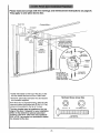
Adjustment
I
Step 2
Adjust the Force
Force adjustment controls are located on the back
_anel of the opener. Force adjustment settings
regulate the amount of power required to open and
close the door.
The door will stop in the up direction if anything
interferes with its travel. The door will reversein the
down direction if anything interferes with its travel
(including binding or unbalanced doors).
If the forces are set too light, door travel may be
interrupted by nuisance reversals in the down
direction and stops in the up direction. Weather
conditions can affect the door movement, so
occasional adjustment may be needed.
Too much force on the door will interfere with
the proper operation
of the safety reverse
system. The door might not reverse properly
when required and could seriously injure or kill
someone under it. Do not increase the force
beyond the minimum amount required to close
the door. Do not use the force adjustments to
compensate for a binding or sticking garage
door. Test the safety reverse system following
all adjustments to force levels. See page 30.
Back panel of
door opener
Force
Adjustment
Controt
The maximum force adjustment range is 260 degrees,
about 3/4 of a complete turn. Do not force controls
beyond that point. Turn force adjustment controls
with a screwdriver.
Adjustment Label
How and When to Adjust the Forces
Test the DOWN (close) force
Make 10 degree turn adjustments until the door stops
easily: After each adjustment, run the opener through
a complete travel cycle.
Grasp the door bottom when the door is about
halfway through DOWN (close) travel. The door
should reverse. Reversal halfway through down
travel does not guarantee reversal on a one-inch
obstruction. See page 30. If the door is hard to
hold or doesn't reverse, decrease the DOWN (close)
force by turning the control counterclockwise.
If the door doesn't open atleast5
feet
Increase UP (Open) force by turning the control
clockwise. Make 10 degree turn adjustments until
door opens completely, Re-adjust the UP limit if
necessary. After each adjustment, run the opener
through a complete travel cycle.
Make 10 degree turn adjustments until the door
reverses normally. After each adjustment, run the
opener through a complete cycle.
If the door reverses during the down (close) cycle
and the opener lights aren't flashing
Test the UP (open) force
Increase DOWN (close) force by turning the control
clockwise. Make 10 degree turn adjustments until the
door completes a close cycle. After each adjustment,
run the opener through a complete travet cycle. Do
not increase the force beyond the minimum
amount required to close the door.
Grasp the door bottom when the door is about
halfway through UP (open) travel. The door should
stop. If the door is hard to hold or doesn't stop,
decrease UP (open) force by turning the control
counterclockwise.
29
Adjustment
Step 3
Test The Safety Reversing
Sensor
I
• Press the remote control push button to open the
door.
• Place the opener carton in the path of the door.
• Press the remote control push button to close the
door. The door will not move more than an inch,
and the opener light will flash.
Professional service is required if the opener
closes the door when the safety reversing
sensor is obstructed.
The garage door opener will not close from a
remote control if the indicator light in either
sensor is off(alerting you to the fact that the
sensor is misaligned or obstructed),
The garage door can be closed by pressing and
holding the Door Control push button until down
travel is completed.
Adjustment Step 4
Test the Safety Reverse
System
I
Test:
• Place a one-inch board (or a 2x4 laid flat) on the
floor, centered under the garage door.
• Operate the door in the down direction. The door
must reverse on striking the obstruction.
L_
Adjustment:
o 'ooo
i
If the door stopson the obstruction, it is not traveling
far enough in the down direction.
• Increase the DOWN limit by turning the DOWN
limit adjustment screw counterclockwise 1/4 turn.
• Repeat the test.
On a sectional door, make sure limit adjustments
do not force the door arm beyond a straight up
and down position. See the illustration on page 26.
/
• When the door reverses on the one-inch board,
remove the obstruction and run the opener through
3 or 4 complete travel cycles to test adjustment.
If the door will not reverse after repeated
adjustment attempts, call Sears Service Center
for garage door opener service.
(or a 2x4 laid flat)
Important
safety check
Repeat Adjustment
Steps 1,2 and 4 after:
• Each adjustment of door arm length, force controls
or limit controls.
• Any repair to or adjustment of the garage door
(including springs and hardware).
• Any repair to or buckling of the garage floor.
• Any repair to or adjustment of the opener.
3O
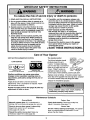
IMPORTANT
SAFETY INSTRUCTIONS
To reduce the risk of severe injury or death to persons:
1. READ AND FOLLOW ALL INSTRUCTIONS.
2. Do not permit children either to operate or to
play with the opener. Keep remote control in a
location inaccessible to children.
3. Operate opener only when the door is in full
view and free from any obstruction. Keep the
door in sight until it is completely closed. NO
ONE SHOULD CROSS THE PATH OF THE
MOVING DOOR.
4. Check safety reversal system monthly. See
page 30. The garage door MUSTreverse
on
contact with a one-inch (or a 2x4 board laid
flat) object placed on the floor. If an adjustment
is made to either the force or the limit of travel,
both adjustments may be needed and the
safety reversal system must be checked.
Failure to properly adjust the opener may
result in severe injury or death.
5. If possible, use the emergency release only
when the door is in a closed position. Caution
should be taken whenever the disconnect cord
is actuated with the door open. Weak or broken
springs may cause the door to fall rapidly,
causing injury or death to persons.
6. KEEP GARAGE DOORS PROPERLY
BALANCED. See page 3. An improperly
balanced door may not [everee when required
and could result in severe injury or death.
Repairs to cables, spring assemblies and other
hardware must be made by a professional
garage door person.
7. Disconnect the electric power to the garage
door opener before making any repairs or
removing the covers.
8.SAVE THESE INSTRUCTIONS.
Care of Your Opener
The remote control
Limit and force adjustment controls
Limit Controls
Force Controls
Adjustment Label
(Located on the left side panel)
Adjustment Label
(Located on the dght side panel)
3-FUNCTION
Open this end
The lithium batteries should
first to avoid
cracking
produce power for up to
5 years. To replace batteries,
use the visor clip or screwdriver
blade to pry open the case, as
Twist here
shown. ("Open" location is
COMPAC_
to
open
stamped on back of remote
control case.) Insert batteries positive side down.
Weather conditions may cause some minor
changes in door operation requiring some readjustments, particularly during the first year of
operation.
Replace cover as follows. 3-Function remote: Insert
the 3 tabs at the opposite end and snap shut. Compact
3-Function remote: Snap shut along both sides.
Dispose of old batteries properly.
Pages 28 and 29 refer to the limit and force
adjustments. Only a screwdriver is required. Follow
the instructions carefully.
Repeat the safety reverse test (page 30) after any
adjustment of limits or force.
Maintenance
Schedule
Once a Month
Twice a Year
Manually operate door. If it is unbalanced or
binding, call for professional garage door service
Check chain tension. Disconnect trolley first.
Adjust if necessary (See page 11 ).
Once a Year
Check to be sure door opens & closes fully.
Adjust limits and/or force if necessary.
(See pages 28 and 29.)
Oil door rollers, bearings and hinges. The opener
does not require additional lubrication. Do not
grease the door tracks.
Repeat the safety reverse test. Make any
necessary adjustments (See page 30).
31
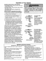
Operation of Your Opener
Activate the opener with any of the following:
• The Remote Control: Hold push button down until
the door starts to move.
• The Door Control: Hold push button down until the
door starts to move.
Weak or broken springs could allow an open
door to fall (either rapidly or unexpectedly),
resulting in serious injury, death or property
damage.
If possible,
use the emergency
release rope and handle onlywhen the door is
fully closed.
• The Outdoor Key Switch or Keyless Entry.
(See Accessories)
When the opener is activated with the safety
reversing sensor installed and correctly aligned:
1. If open, the door will close. If closed, it will open.
2. If closing, the door will reverse.
3: If opening, the door will stop (allowing space for
entry and exit of pets and for fresh air).
4. If the door has been stopped in a partially open
position, it will close.
5. If obstructed while closing, the door will reverse.
6. tf obstructed while opening, the door will stop.
7. The garage door will reverse in the closing cycle,
and the opener lights will blink for 5 seconds, when
the invisible beam is broken. If fully open, the door
wil! not close when the beam is broken. The sensor
has no effect in the opening cycle.
If the sensor is not installed or not aligned correctly,
the door won't close from any remote control. You
can close the door with the Door Control, the
Outdoor Kay Switch, or Keyless Entry, however, if
you activate them untildown travelis complete. If
you release them too soon, the door will reverse.
The Opener Lights will turn on under the following
conditions: When the opener is initially plugged in;
when the power is interrupted; when the opener is
activated. It will turn off automatically after 4-1/2
minutes or provide constant light when the Light
feature on the Premium Control Console is activated.
Bulb size is 75 watts maximum.
rrn
Emergency
Release Handle
(Pull Down)
Manual disconnect
position
The lockout feature
prevents the trolley from
reconnecting automatically. Pull the
emergency handle down
and back (toward the
opener). The door can
then be raised and
Trolley
_1_
lowered manually as
Emergency
often as necessary. To
Release Handle
•
(Pull Down & Back disengage the lockout
Towards
Opener)feature, pull the
Lockout position
emergency handle
straight down. The trolley
will reconnect on the next
UP or DOWN operation.
SECURITY+ models: Lights will also turn on when
someone walks through the open garage door. With
a Premium Control Console, this feature may be
turned off as follows: With the opener lights off, press
and hold the light button for 10 seconds, until the
light goes on and off again. To restore this feature,
start with the opener lights on, then press and hold
the light button for 10 seconds.
(SECURITY+
To open the door
manually:
The door should be fully
closed if possible. Pull
down on the red
emergency release
handle and lift the door
manually. To reconnect
the door to the opener,
press the Door Control
push button.
Operation
of the Door Controls
models: See additional programming features, next page,)
Press the lighted push button to open or close the
door.
Premium Console (cont.):
Lock feature: The Lock feature is designed to
prevent operation of the door from remote controls.
However, the door will open and close from the
Door Control, the Outdoor Key Switch and the
Keyless Entry Accessories.
To activate: Press and hold the small round Lock
button for 2 seconds. The push button light wilt
flash as long as the Lock feature is on.
To turn off" Press and hold the Lock button again
for 2 seconds.The push button light will stop
flashing. The Lock feature will also turn off
whenever the SRT button on the opener panel is
activated.
Press again to reversethe door during the closing
cycle or to stopthe door while it's opening.
Premium Console:
Lightfeature:Press
the large round Light button. If
the opener light is off, it will turn on. If the opener
light is on, (even in the 4-1/2 minute automatic
cycle) it will turn off.
But if you use the Light button to turn the lights on
and then activate the opener, the lights will turn off
after 4-1/2 minutes.
The Light button will not control the opener lights
when the door is in motion.
32
Receiver and Remote Control Programming
SI ,CIJRI'I -"I;
To comply with FCC rules, adjustment or modifications of this receiver and/or
transmitter are prohibited, except for changing the code setting or replacing
the batte W. THERE ARE NO OTHER USER SERVICEABLE
PARTS,
Your garage door opener receiver and remote control
have been pre-set at the factory. The door will open
when you press the LARGE remote control push
button. The code between the remote control and the
receiver changes with each use, randomly accessing
over 100 billion new codes.
Children operating or playing with a garage
door opener can injure themselves or others.
The garage door could close and cause serious
injury or death. Do not allow children to operate
the door push button(s) or remote control(s).
The 3-function remote control can also activate
additional SECURITY+ garage door openers and/or
light controls.
Your SECURITY+
A moving garage door could injure or kill
someone under it. Activate the opener only
when you can see the door clearly, it is free of
obstructions, and is properly adjusted.
opener will operate with:
• several SECURITY+ remote controls (with blue
push buttons) utilizing up to 8 functions.
• one SECURITY+ Keyless Entry System
(Model 139.53684).
Follow the instructions below to program your opener
to match any additional remotes you may purchase.
See Accessories on page 38.
Figure 1
Select a remote control push
button to operate opener
To Add A Remote Control
If you have a Premium Control
Figure
Console:
1. With the door closed, press and hold a remote
control push button. See Figure 1.
SECURITY,IP
Garage Door Opener
SECURITY'I"
3-Function
Remote Control
2. Press and hold the Light button on the door
control.
2
3. Press and hold the door control push button.
4. After the opener light flashes, release all buttons.
Test by pressing the remote push button.
_oo_
I
SRT (learn)
Button
Indicator
Light
BACK
PANEL
If you do not have a Premium Control Console:
1. Press and holdthe selected remote control push
button. See Figure 1.
_a
/Code
prog_tructlons
ire
also located on the opener panel.
2. Then press and release the SRT (learn) button on
the back panel of the opener, Figure 2. The
indicator light on the panel will begin to blink and
the opener light will flash once.
To Control the Opener Light (Premium Consoles)
With SECURITY+ remote controls, a push button can
be programmed to operate the opener light without
opening the door.
3. Release the remote push button.
Test by pressing the remote push button.
1. With the door c/osed, press and hold the remote
button that you want to control the light.
To Erase All Remote Control Codes
2. Press and hold the Light button on the door
control.
Press and hold the SRT button on the opener panel
until the indicator light turns off (about 6 seconds). All
remote control codes are now erased. Then follow
the steps above to re-program each remote control.
3. Press and hold the Lock button on the door control.
4. After the opener light flashes, release all buttons.
Test by pressing the remote push button. The opener
light should turn on or off but the door should not move.
33
Having a Problem?
Situation
Probable
Cause and Solution
The opener doesn?
operate from either
the Door Control or
the remote control:
1. Does the opener have electric power? Plug a lamp into the outlet. If it doesn't light,
check the fuse box or the circuit breaker. (Some outlets are controlled by a wall switch.)
2. Have you disabled all door locks? Review installation instruction warnings on Page 11.
3. Is there a build-up of ice or snow under the door? The door may be frozen to the
ground. Remove any restriction.
4. The garage door spring may be broken. Have it replaced.
5. Repeated operation may have tripped the overload protector in the motor. Wait
15 minutes. Try again.
Opener operates
from the remote
control, but not from
the Door Control:
1. is the Door Control lit? If not, remove the bell wire from the opener terminal screws.
Short the red and white terminals by touching both terminals at the same time with a
piece of wire. If the opener runs, check for a faulty wire connection at the Door
Control, a short under the staples, or a broken wire.
2. Are the wiring connections correct? Review Step 6, page 18.
The door operates
from the Door
Control, but not from
the remote control:
1. Is any door push button flashing? If your model has the Lock feature, make sure the
lock is Off.
2. Your opener needs to re-learn a remote control code. Refer to Instructions on the
opener panel.
3. Program the receiver to match the remote control code.
4. Repeat the receiver programming procedure with all remote controls.
The remote control
has short range:
1. Change the location of the remote control in your car.
2. Check to be sure the antenna on the side or back panel of opener extends fully
downward.
3. Some installations may have shorter range due to a metal door, foil backed
insulation, or metal garage siding. (Antenna Extender Kit 41A3504)
Opener noise is
disturbing in living
quarters of home:
If operational noise is a problem because of proximity of the opener to the living
quarters, the Vibration Isolator Kit 41A3263 can be installed. This kit was designed to
minimize vibration to the house and is easy to install.
The garage door
opens and closes
by itself:
1. Be sure that all remote control push buttons are off.
2. Remove the bell wire from the Door Control terminals and operate from the remote
control only. If this solves the problem, the Door Control is faulty (replace), or there is
an intermittent short on the wire between the Door Control and the opener.
3. Clear memory and reprogram all remote controls.
The door doesn't
open completely:
1. Is something obstructing the door? Remove the obstruction or repair the door.
2. If the door has been working properly but now doesn't open all the way, increase the
up force. See page 29.
3. If door opens at least 5 feet, the travel limits may need to be increased. One turn
equals 2 inches of travel. See page 28.
Repeat the safety reverse test after the adjustment is complete.
The door stops but
doesn't close
completely:
Review the travel limits adjustment procedures on page 28.
Repeat the safety reverse test after any adjustment of door arm length, close
force or down limit.
34
Having a Problem?
(continued)
Situation
Probable
Cause & Solution
The door opens but
won't close:
1. If the opener lights blink, check the safety reversing sensor. See page 23.
2. If the opener lights do not blink and it is a new installation, check the down force.
See Adjustment Step 2, page 29. For an existing installation, see below.
Repeat the safety reverse test after the adjustment is complete.
The door reverses for
no apparent reason
and opener lights
don't blink:
1. Is something obstructing the door? Pull the red emergency release handle. Operate
the door manually. If it is unbalanced or binding, call for professional garage door
service.
2. Clear any ice or snow from the garage floor area where the door closes.
3. Review the force adjustment procedures on page 29.
4. If door reverses in the fully closedposition, decrease the travel limits (page 28).
Repeat safety reverse test after adjustments to force or travel limits, The need
for occasional adjustment of the force and limit settings is normal. Weather
conditions in particular can affect door travel•
The door reverses for
no apparent reason
and opener lights
blink for 5 seconds
after reversing:
Check the safety reversing sensor. Remove any obstruction or align the receiving eye.
See page 23.
The opener fight:
• •. doesn't turn on:
Replace the light bulbs (75 watts maximum). Use a standardneckgarage
bulb if regular bulb burns out.
door opener
•.. doesn't turn off,"
Is the Light feature on? Turn it off
The opener strains or
maximum force is
needed to operate
door:
The opener motor
hums briefly, then
won't work:
The door may be out of balance or the springs are broken. Close the door and use the
emergency release to disconnectthe trolley.Open and close the door manually. A properly
balanced door willstay in any point of travel while being supported entirelyby its springs. If it
does not, disconnectthe opener and call a professionalgarage door serviceman. Do not
increase the force to operate the opener.
1. The garage door springs are broken. See above.
2. If the problem occurs on the first operation of the opener, door may be locked. Disable
the doorlock. If the chain was removed and reinstalled, the motor may be out of phase.
Remove the chain; cycle the motor to the down position. Observe the drive sprocket.
When it turns in a clockwise direction and stops in the down position, reinstall the chain.
Repeat the safety reverse test after the adjustment is complete,
The opener won't
operate due to
power failure:
1. Use the emergency release to disconnect the trolley. The door can be opened and closed
manually. When the power is restored, press the Door Control push button and trolley will
automatically reconnect (unless trolley is in lockout position.) See page 32.
2. The Emergency Key Release accessory (for use on garages with no service door)
disconnects the trolley from outside the garage in case of power failure.
The chain droops
or sags:
It is normal for the chain to droop slightly in the closed door position. Use the
emergency release to disconnect the trolley. If the chain returns to normal height when
the trolley is disengaged and the door reverses on a one-inch board, no adjustments
are needed (see page 11 ).
35
Repair Parts, rail assembly and installation
Refer to Parts Diagram document for part info.
Repair Parts, opener assembly
Refer to Parts Diagram document for part info.
Accessories
Sears offers many useful accessories for your garage door opener. They are illustrated below with
Sears model numbers and descriptions.
139.53702
,f
139.53681
Emergency Key Release:
Requiredfor a garage with NO
access door. Enables homeowner
to open garage door manually from
outside by disengaging trolley.
Outdoor
Key Switch:
Operates the garage door
automatically from outside when
remote control is not handy.
10 Foot Rail Extension:
139.53686
Plug-In Light Control:
Enables homeowner to turn on a
lamp, television or other appliance
from car, bedside, or anywhere in
the home with a remote.
139.53709
Door Clearance Brackets:
To allow a 10 foot door to open fully.
53589
Support Brackets:
SECURITY,I, Keyless Entry:
Enables homeowner to operate garage
door opener from outside by enteringa
password.Also can add a temporary
password for visitors or service
persons. This temporary password can
be limitedto a programmable number
of hours or entries.
8 Foot Rail Extension
To allow an 8 foot door to open fully.
139.53705
SECURITY,I, Compact
3-Function Remote Control:
With loop for attaching key ring.
(Available April, 1997)
139.53684
139.53704
Remote
Includes visor clip.
139.53680
139.53703
SECURITY,I, 3-Function
Control:
(For Sectional Doors On/y)
For finished ceilings or where
additional support is required,
based on garage construction.
Includes brackets and fastening
hardware.
Replaces top brackets and rollers on
door to reduce height of door travel.
For use when installing opener in
garage with low headroom clearance.
To Add the Keyless Entry
We recommend that you program your password
before you install the Keyless Entry. You will not
need assistance, and you can test the reception at
the mounting location before installation.
If you do not have a Premium Control
Console:
If you have a Premium Control
2. Press the four buttons for the password, then
press and holdthe Enter button. The indicator light
on the door opener panel will blink.
1. Choose a 4-digit password using numbers from
0 to 9 (a number can be used more than once, for
example, 4, 0, 4, 1).
Console:
1. With the doorc/osed, press the four digit password
desired, then press and hold Enter.
3. Press and release the SRT (learn) button on the
opener panel. After the opener light flashes,
release the Enter button.
2. Press and hold the light button on the door control.
3. Press and hold the door control push bar.
4. After the opener light flashes, release art buttons.
Test by pressing the password, then press Enter. The
door should begin to move.
38
Index
Access DoorlOutside
Key Release Accessory ...............................................................................................
4, 5
Chain Tension ..............................................................................................................................................
4, 5, 11
Electrical Safety Warnings ........................................................................................................................
2, 20, 31
Garage Door
Testing for balance, binding and sticking ...................................................................................................
Determining high point of travel:
Sectional door ...................................................................................................................................................
3, 28, 31
12
One-piece door .................................................................................................................................................
13
Disabling existing locks ....................................................................................................................................
3, 11
Door clearance brackets (for garages with low headroom) ...........................................................................
12, 38
Force controls
Adjustment procedures .................................................................................................................................
4, 29
Problems that might require force adjustments ..........................................................................................
34, 35
Safety warnings ..........................................................................................................................................
29, 31
Door hardware .....................................................................................................................
3, 9, 11, 12, 18, 31,32
Maintenance instruction label ........................................................................................................................
11,28
Reinforcement requirements ...........................................................................................................................
4, 24
Removing of all ropes .......................................................................................................................................
3, 11
Possible door damage ...................................................................................................................................
16, 24
Travel limits
Adjustment procedures .....................................................................................................................................
Problems that might require limit adjustments ............................................................................................
Safety warnings ..........................................................................................................................................
Manual (Emergency) Release Rope & Handle
Lockout feature ....................................................................................................................................................
Manual disconnect ...............................................................................................................................................
Safety warnings .................................................................................................................................
28
34, 35
28, 31
32
32
11, 19, 31, 32
Opener Terminals
Door control connections .....................................................................................................................................
Safety reversing sensor connections ...................................................................................................................
18
23
Operational Noise
Sprocket noise .....................................................................................................................................................
Vibration noise (isolator kit) .................................................................................................................................
11
34
Receiver and Remote Control
Programming the receiver ...................................................................................................................................
Erasing all codes .................................................................................................................................................
Activating other openers ......................................................................................................................................
Safety warning .....................................................................................................................................................
Problems with remote control operation ..............................................................................................................
33
33
33
33
34
Safety Reverse Test Procedure ..........................................................................................................................
30
Testing required .................................................................................................................................
11, 30, 34, 35
Safety reverse system problems
Securing header bracket to waft .......................................................................................................................
12
Adjusting travel limits ........................................................................................................................................
28
Applying excessive force on the door ...............................................................................................................
29
Buckling or uneven floor .................................................................................................................................
4, 5
Safety Warnings .........................................................
User instruction
2, 3, 9, 11,12, 16, 18, 19, 20, 21,24, 28, 29, 30, 31, 32, 33
Label for garage wall ........................................................................................................
39
11, 18
For professional installation
Call 24 hours a day, 7 days a week
1-800-865-8500
For the repair or replacement parts you need
Call 7 am - 7 pro, 7 days a week
1-800-366-PART
(1-800-366-7278)
For in-home major brand repair service
Call 24 hours a day, 7 days a week
1-800-4-REPAIR
(1-800-473-7247)
For the location of a Sears Repair Service Center in your area
Call 24 hours a day, 7 days a week
1-800-488-1222
For information on purchasing a Sears Maintenance Agreement or to inquire
about an existing Agreement
Call 9 am - 5 pro, Monday-Saturday
1-800-827-6655
The model number label is located under the light lens on the front end
panel of your opener. When requesting service or ordering parts, always
give the following information:
• Part Number
• Product Type
• Model Number
SEARS
America's Repair Specia/ists
• Part Description
To obtain this Owner's Manual in
Para obtener este Manual del
Spanish, please ask your
sales associate.
propietsrio en espa_ol, sirvase
solicitarlo s su vendedor.
SEARS WARRANTY
FULL 90-DAY WARRANTY
ON GARAGE
DOOR OPENER
For 90 days from the date of purchase, Sears will repair this Garage Door Opener, free of charge, if defective in matedal or workmanship.
LIMITED WARRANTY
From the 91 st day until one year from the date of purchase, Sears will furnish replacement
You pay for labor.
LIMITED WARRANTY
parts for any defective parts, free of charge.
ON MOTOR
1/2HP MOTOR: Afler 1 year and through 5 years, if the motor on this Garage Door Opener is defective,
motor, free of charge. You pay for labor.
Sears will furnish a replacement
1/3HP MOTOR: After 1 year and through 3 years, if the motor on this Garage Door Opener is defective,
motor, free of charge. You pay for labor.
LIMITATION ON LIABILITY
Sears will furnish a replacement
SEARS WILL NOT BE LIABLE FOR LOSS OR DAMAGE TO PROPERTY OR ANY INCIDENTAL OR CONSEQUENTIAL
LOSS OR
EXPENSE FROM PROPERTY DAMAGE DUE DIRECTLY OR INDIRECTLY FROM THE USE OF THIS PRODUCT. Some states do
not allow the exclusion or limitation of incidental or consequential damages, so the above limitation or exclusion may not apply to you.
This warranty does not cover light bulbs or repair parts necessary because of operator abuse or negligence, including the failure to
install, adjust and operate this garage door opener according to instructions contained in the owner's manual.
WARRANTY
STATES.
SERVICE
IS AVAILABLE
BY SIMPLY CONTACTING
THE NEAREST SEARS CENTER/DEPARTMENT
This warranty
applies only while this product is in use in the United States.
IN THE UNITED
This warranty gives you specific legal rights, and you may also have other rights which vary from state to state.
Sears, Roebuck and Co., Dept. 617WA, Hoffman Estates, IL 60179
114A2099J
©1999, All Rights Reserved
Printed in Mexico