1
i i ii
ii
i, ii ii
ii i
i
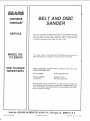
SAVE THIS MANUAL
FOR FUTURE REFERENCE
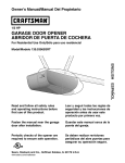
MODEL NO.
113.226423
BELT AND DISC
SANDER
Serial
Number
Model and serial number
may be found on the back
side of the base,
F'rs
C
You should
record
both
mode! and serial number in
a safe place for future use.
BELT AND DISC
SANDER
CAUTION:
® assembly
• operating
e repair parts
Read GENERAL
and ADDITIONAL
SAFETY
INSTRUCTIONS
carefully
Sold
PART
NO
SP500t
by
SEARS,
ROEBUCK
AND
CO.,
Chicago,
IL 60684
U.S.A.
_:_;_ !_::D
t;
_. _ ;:
i=
FULL ONE YEAR WARRANTY
.......
i
, ,
,
i
ON CRAFTSMAN
BELT AND DISC SANDER
If within one year from the date of purchase, this Craftsman Belt and Disc Sander fails due
to a defect in material or workmanship,: sears will repair it, free of charge.
WARRANTY SERVICE IS AVAILABLE BY RETURNING TH E BELT AND DISC SANDER TO
THE NEAREST SEARS RETAIL/CATALOG STORE OR SERVICE CENTER/DEPARTMENT IN
THE UNITED STATES:
THIS WARRANTY APPLIES ONLY WHIL E THIS PRODUCT IS IN USE IN THE UNITED STATES.
This warranty gives you specific
vary from state to state.
legal rights, and you may also have other rights which
SEARS, ROEBUCK AND CO., Sears Tower, BSC 41-3, Chicago, IL 60684
general safety instructions for power tools
1. KNOW YOUR POWER TOOL
Read and understand the owner's manual and
Iabels affixed to the tool. Learn its application and
limitations as welI as the specific potential hazards
peculiar to this tool.
2. GROUND ALL TOOLS
This tool is equipped with an approved 3-conductor
cord and a 3-prong grounding type plug to fit the
proper grounding type receptacle. The_green conductor in the cord is the grounding wire. Never
connect the green wire to a live terminal.
3. KEEP GUARDS IN PLACE
In working order, and in proper adjustment and
alignment.
4. REMOVE ADJUSTING KEYS AND
WRENCHES
Form a habit of checking to see that keys and
adjusting wrenches are removed from toot before
turning it on.
5. KEEP WORK AREA CLEAN
Cluttered areas and benches invite accidents.
Floor must not be slippery due to wax or sawdust.
6. AVOID DANGEROUS ENVIRONMENT
Don't use power tools in damp or wet locations or
expose them to ra_noKeep work area welt lighted.
Provide adequate surrounding work space.
7. KEEP CHILDREN AWAY
All visitors should be kept a safe distance from
work area.
8. MAKE WORKSHOP CHILD-PROOF
--with padlocks, master switches, or by removing
starter keys.
9. DON'T FORCE TOOL
it wilt do the job better and safer at the rate for
which it was designed.
10. USE RIGHT TOOL
Don't force tool or attachment to do a job it was
not designed for.
11. WEAR PROPER APPAREL
Do not wear loose ctothing, gloves, neckties or
jewelry (rings, wrist watches) to get caught in moving p_.rts. Nonslip footwear isrecommended. Wear
protective hair covering to C0ntain iong ha
long sleeves above the elbow.:; :
......, ,......
12, USE SAFETY
GOGGLES
(Head Protection)
Wear Safety goggles
_must comply
with ANSI
Z87.1 ) at all times Everyday eyeglasses only have
impact resistant lenses_ they are NOT safety gJasses. Also, use face or dust mask if cutting operation
is dusty, and ear protectors (plugs or muffs) during
extended
periods of operation,
13. SECURE
WORK
Use clamps or a vise to hold work when practical
It's safer than using your hand. frees both hands
to operate tool.
14. DON'T OVERREACH
Keep proper footing and batance
al all times.
15. MAINTAIN TOOLS WITH CARE
Keep tools sharp and clean for best and safest
performance. Follow instructions for lubricating and
changing accessories.
16. DISCONNECT TOOLS
Before servicing; when changing accessories such
as blades, bits, cutters, etc.
17, AVOID ACCIDENTAL STARTING
Make sure switch is in "OFF" position before plugging in.
18. USE RECOMMENDED ACCESSORIES
Consult the owner's manual for recommended accessories. Follow the Enstructions that accompany
the accessories. The use of improper accessories
may cause hazards.
19, NEVER STAND ON TOOL
Serious injury could occur if the tool is tipped or if
the cutting tool is accidentally contacted.
Do not store materials above or near the toot such
that it is necessary to stand on the tool to reach
them.
20. CHECK DAMAGED PARTS
Before further use of the tool, a guard or other part
that is damaged should be carefully checked to
ensure that it wilt operate properly and perform its
intended function. Check for alignment of moving
parts, binding of moving parts, breakage of parts,
mounting, and any other conditions that may affect
its operation. A guard or other part that is damaged
should
be properly repaired or replaced,
21. DIRECTION OF FEED
Feed work into a blade or cutter against the direction of rotation of the blade or cutter only.
22. NEVER LEAVE TOOL RUNNING UNATTENDED
Turn power off. Don't leave tool until it comes to a
complete stop.
additional safety instructions for beff and disc sander
Safety is a combination of operator common sense and
alertness at all times when the sander is being used.
e. Never turn your Sander "ON" before clearing the belt table and worktable of all objects.
f. Make sure the sanding belt runs in the right
direction (directional arrow on back side of
belt). Always have the tracking adjusted correctly so that the belt does not run off the pulleys.
g. Hold the work firmly when sanding on the belt
and against the worktable when sanding on
the disc.
h. Always adjust the worktable to within a
maximum of 1/16-inch of the sanding disc
or belt.
i. When sanding a large piece of material, provide additional support at table height.
j. Never leave the machine work area when
the power is on, before the machine has
come to a complete stop, or without removingand storing the switch key.
k. Do not perform layout, assembly or setup
work on the table while the sander is
operating.
1. Turn sander "OFF" and remove plug from
power supply outlet before installing or
removing an accessory.
m Use only RECOMMENDED ACCESSORIES
listed on page 2I.
WARNING: For your own safety, do not attempt to
operate your Belt and Disc Sander until it is completely assembled and installed according to the
instructions..,
and until you have read and understand the following:
1.
2.
3.
4.
Page
General Safety Instructions for Power Tools. 2
Getting to Know Your Sander ...........
15
Basic Operation .......................
17
Maintenance ..........................
20
5. Stability of Machine
If there is any tendency for the machine to tip over
or move during certain operations such as when
sanding long heavy boards, the sander should be
bolted down.
6. Location
The machine should be positioned so neither the
operator nor a casual observer is forced to stand
in line with the sanding belt or disc. This machine
is intended for indoor use only.
9_
7. Kickback
When sanding on the Disc, always apply the workpiece left of center to the left side of the disc. Applying the workpiece to the right side could cause
it to fty up (kickback) which could be hazardous.
8. Protection: Eyes, Hands, Face, Ears and Body
a. Always wear safety goggles (not glasses)
that comply with ANS1 Z87.1, Wear face shield
if operation is dusty, Wear ear plugs or muffs
during extended periods of operation, Do not
wear gloves, jewelry or watches. Roll long
sleeves above the elbow. Tie back long hair.
b. Do not sand pieces of material too small to
hold by hand.
c. Avoid awkward hand positions, where a
sudden slip could cause a hand to move
into sanding disc or belt.
d. Neverclimbonthe
machine.
If any part of this Belt and Disc Sander should
break, bend, or fail in any way or any electrical
component fail to perform properly, or if any is
missing, shut off power switch, remove power supply cord from power supply and replace damaged
missing and/or failed parts before resuming operation.
10. Do not sand with the workpiece unsupported. Support it with the backstop or worktable. The only
exception is curved work performed on outer end
of belt (idler pulley).
11. To avoid entanglement in spindle, do not operate
sander with sanding plate and/or guard removed.
CAUTION: This Belt and Disc Sander is designed
to sand wood or wood like products only. Attempts
to sand or grind other materials could result in fire,
injury or damage to the product.
additional safety instructions for belt and disc sander
12; Think Safety
Safety is a combination of operator common sense
and alterness at all times when the sander is in
operation.
The operation
of any power tool can "es@t in foreign
objects being thrown into the eyes, which can result in
severe eye damage. Always wear safety goggles (not
glasses) complying with ANSI Z87,1 (shown on Pack _
age) before beginning
power tool operation.
Safety
Goggles are available at Sears retail or catalog store&
i
I
I
i
•
•
'
WARNING: DO NOT ALLOW FAMILIARITY (GAINED FROM FREQUENT USE OF YOUR MACHINE) TO
BECOME COMMONPLACE, ALWAYS REMEMBER THAT A CARELESS FRACTION OF A SECOND IS
SUFFICIENT TO INFLICT SEVERE INJURY.
•
I
ll[[J
.L
[[
I
'
ii
I
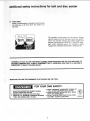
READ AND FOLLOW THE WARNINGS THAT APPEAR ON THE TOOL:
]
FOR YOUR
1, READ AND UNDERSTAND
OWNER'S MANUAL
BEFORE OPERATING MACHINE.
2. WEAR SAFETY GOGGLES AND DUST MASK.
3. MAINTAIN 1/16" MAXIMUM CLEARANCE
BETWEEN
TABLE AND SANDING BELT OR DISC.
i
ii
OWN SAFETY:
4. AVOID "KICKBACK"
(WORKPIECE
THROWN AT
YOU)--DO
NOT USE RIGHT HALF OF DISC,
5. ALWAYS SUPPORT WORKPIECE
WITH "BACKSTOP" OR "WORKTABLE,"
6. DO NOT WEAR GLOVES, NECKTIE OR LOOSE
CLOTHING.
TIE BACK LONG HAIR.
E82443
motor
specifications
and electrica
This machine is designed to use, and is equipped with,
a 3450 RPM motor, It is wired for operation on 110-120
volts, 60 Hz., alternating current. (TOOL MUST NOT
BE CONVERTED TO OPERATE ON 230 VOLT).
For replacement motor refer to parts list is this manual.
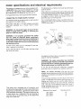
CONNECTING TO POWER SUPPLY OUTLET
This machine must be grounded while in use to protect
the oeprator from electric shock.
Plug power cord into a 110-120V properly grounded
type outlet protected by a 15-amp. fuse or circuit
breaker.
WARNING: Do not permit fingers to touch the terminals of plugs when installing or removing the
plug to or from the outlet.
WARNING: If not properly grounded this power
tool can cause an electrical shock, particularly
when used in damp locations close to plumbing. If
an electrical shock occurs there is the potential of
a secondary hazard such as your hands contacting
the sanding surface.
requirements
This plug requires a mating 3-conductor grounded type
outlet as shown.
If the outlet you are planning to use for this power tool
is of the two prong type, DO NOT REMOVE OR ALTER
THE GROUNDING PRONG IN ANY MANNER. Use
an adapter as shown below and always connect the
grounding lug to a known ground.
It is recommended that you have a qualified electrician
replace the TWO prong outlet with a properly grounded
THREE prong outlet.
GROUNDING LUG
SCREW
3-PRONG
\
_1_
If power cord is worn or cut, or damaged in any way,
have it replaced immediately.
_J_,KESURE TH_S 5
"x
HECEPT,_CLE
ADAPTER
If your unit is for use on 110-120 volts, and has a plug
that looks like below.
An adapter as shown above is available for connecting
plugs to 2-prong receptacles.
WARNING: The green grounding lug extending
from the adapter must be connected to a permanent
ground such as to a properly grounded outlet box.
Not all outlet boxes are properly grounded.
_3-PRONG
"_'-,,
If you are not sure that your outlet box is properly
grounded, have it checked by a qualified electrician
GROUNDING
LUG
PRONG
_
PROPERLY
GROUNDED
3-PRONGOUTLET
This power tool is equipped with a 3-conductor cord
and grounding type plug which has a grounding prong,
approved by Ur_derwriters' Laboratories and the Canadian Standards Association. The ground conductor has
a green jacket and is attached to the toot housing at
one end and to the ground prong in the attachment
plug at the other end,
NOTE: The adapter illustrated
is for use only if you
already have a properly grounded 2-prong receptacle.
Adapter is not allowed in Canada by the Canadian Elec*
tricaf Code.
The use of any extension cord will cause some ioss of
power, To keep this to a minimum and to prevent overheating and motor burn-out,
use the table below to
determine
the minimum wire size (A.W,G.) extension
cord. Use onty 3 wire extension cords which have 3prong grounding
type plugs and 3-prong receptacles
which accept the tools plug.
Extension Cord Length
Wire Size A,W.G.
Upto 100 Ft.
100 - 200 Ft.
200 - 400 Ft.
!6
14
t0
:
Unpacking
AndChecking
Contents.......
__._..
Mounting Belt and Disc Sander to Workbench
Clamping Bell and Disc Sander to Workbench
Installing
Installing
Installing
Installing
Installing
Squaring
Timing Belt ......................
Pulley Cover ....................
Sanding Disc Plate ...............
Backstop .......................
Table Assembly ..................
Table Assembly ..................
6
. 7
.. 8
9
t0
10
11
12
13
,
n
Be!t Table Stop ..........................
Surface Sanding on Sanding Belt ...........
End Sanding on the Sanding Belt ...........
Sanding Curved Edges ...................
Maintenance ..............................
Lubrication .............................
18
18
18
19
20
20
Troubleshooting ...........................
Recommended Accessories ..................
Repair Parts ..............................
21
2t
22
u,
Jl
..#,€_
•
.
.....
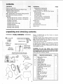
unpacking and checking contents
TOOLS NEEDED
_
_=_--;7it6"WaENCH
'
"
I/2" WREI_H
3/4_ WRENCH
Model II3,226423 Belt and Disc Sander is shipped
complete in one carton.
_
(_)
__
each item with illustration and "Table of Loose Parts."
Make certain all items are accounted for, before disSeparateany
atl packing
parts from
packing materials and check
carding
material.
=
_:
PHILLIPStYPE
;
SCREWDRIVER
COMBINATION
SQUARE
MUST
BETRUE
STRAIGHT
EDGE
OF
DRAWLIGHT
THIS EDGEMUSTBE
:
BOARD 3!4" THICK
:
:::
:
:
:
ts any parts are missing, do not attempt to assemble
the Belt and Disc Sander, plug in the power cord, or
turn the switch on until the missing parts are obtained
and installed correctly.
LINE:ON
BOARD
i : A_ONG
q'HS EOGE
: ....
PERFECTLY
STRAIGHT WARNING: For your own safety, never connect
plug to power source outlet until all assembly steps
;
are complete and until you have read and underSHOULDBENOGAPOROVERLAPHEREWHEN
stood the entire owners manual.
SQUAREIS FLIPPEDOVERtN DOTTEDPOSITION i:
:
;
--
.....
ITEM
A
B
C
D
E
F
G
H
J
TABLE OF LOOSE PARTS
Belt and Disc Sander
Assembly .....................
Owners Manual .................
Table Assembly .................
Sanding Plate ..................
Sanding Disc ...................
Table Support Rod ..............
Bag Assembly Part #507303 .....
Containing the following parts:
Switch, Key ...................
Wrench, Hex "L" I/8 ............
Backstop .....................
Washer, 1/4" . .................
Bolt, Hex 1/4-20X1/2 ............
Bolt, Hex 5/16-t8Xl
............
Knob ........................
Setscrew 1/4-20Xt/4" . ..........
Screw 1/4-2OXl-3/4" . ...........
Pulley Cover ..................
Timing Belt ...................
QTY.
!
1
1
1
t
I
1
1
t
1
1
2
1
t
1
!
t
assembly
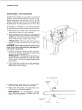
MOUNTING BELT AND DISC SANDER
TO WORKBENCH
If belt and disc sander is to be used in a permanent
location, it should be fastened securely to a firm supporting surface such as a workbench. A 5/16" bolt, flatwasher, Iockwasher, and hex nut (not included) should
be used at each mounting hole to secure the belt disc
sander to the workbench.
If mounting
to a workbench,
holes should be drilled
through supporting surface of the workbench as follows:
1. Set the belt disc sander on the workbench
exact position where it is to be mounted,
in the
2, Push a pencil through one of the mounting
holes
and place a mark on the workbench
that marks the
center of the mounting hole opening. Mark the other
three mounting hotes using the same method.
SPECIAL
NOTE:
Make sure the pencil marks are
placed very near the center of the mounting
hole
openings,
WARNING:
Check under workbench
before drilling
holes to make sure electrical
wires, gas pipes, etc.,
will not be hit by drill bit.
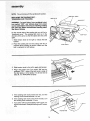
3.
Remove the belt disc sander from the workbench.
Drill four 3/8" diameter holes using the pencil marks
as the center of the drilled holes.
MOUNTING HOLES
SPECIAL NOTE: It is highly recommended that you
place a soft foam pad between your belt disc sander
and workbench. The use of this pad will reduce noise
and vibration.
4. Place the belt disc sander back on the workbench.
Align the mounting holes in the sander with the
drilled holes in the workbench.
BELT AND DISC SANDER
I!2'/OPTIONAL
FOA_ PAD
.
X,X_.
Insert four 5/16" bolts through the mounting holes
and through the dritled holes in the workbench.
6, Place a 5/16" flat washer, 5116" lockwasher,
5/16" hex nut on the bolt and tighten,
and a
SPECIAL NOTE: Do not overtighten mounting
bolts - leave some cushion in the foam pad for absorbing noise and vibration.
/
WORKBENCH
,
i
J
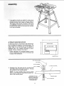
assembly
7. If you prefer to mount your sander to a leg set we
recommend the leg set for bench top tools which is
available through Sears Retail or Catalog Stores,
The number of this leg set is 9-22244. This leg set
is an optional accessory and instructions to mount
the belt and disc sander to this leg set are included
in the leg set package.
24'
ALTERNATE
MOUNTING METHOD
t
MOUNTING BOARD
[
An alternate method of mounting the belt and disc sander is to fasten the sander to a mounting board. The
board should be of sufficient size to avoid tipping of
sander while in use. Any good grade of plywood or
ch_pboard with a 3/4" minimum thickness is recommended. (Thinner chipboard can break.)
18"
1, Follow instructions for mounting sander to workbench, substituting a board 18" X 24" minimum size
in place of the workbench.
/
MOUNTINGHOLES
BELTAND DISCSANDER
:::::::::::
\' Y
5/!6" HEXNUT.Nk_k_._.,"
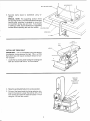
2,
Substitute 5/16" flat head bolts for mounting boits
(NOT INCLUDED). Bolt length should be 1-1/2 plus
the thickness of the mounting board.
"_,_'_:_===1
_'_
I ! 1i
,
NOTE: For proper stability, holes must be counter
sunk so screw heads are flush with the bottom surface of the mounting board.
1_2"FOAM PAD OPTIONAL
/"
/'
COUNTERSINK
THEAREA
AROUND EACH HOLE SO BOLT
HEADWILLNOTPROTRUDE
BELOWBOl-fOM SURFACE
OF MOUNTINGBOARD.
,
,
I ,
",
/
/
,"
i ",
.J ] _.,
\
MOUNTINGBOARD
5;t6" FLATHEADBOLT
MOUNTING BOLTS
BELT AND DISC SANDER
Securely
clamps.
clamp board
to workbench
using "C"
SPECIAL NOTE: The supporting surface where
belt and disc sander is mounted should be examined
carefully after mounting is complete to insure that
no movement during use can occur, tf any tipping
or walking is noted, secure workbench or supporting
surface before operating belt and disc sander.
MOUNTING
BDARO
WORKBENCH
C'CLAMP
i
TABLE
LOCKING BO[TS
BE; _
TABLE
WRENCH
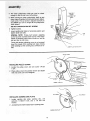
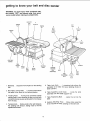
INSTALLING TIMING BELT
IMPORTANT -- Do not overtighten timing belt tension
by adjusting timing setscrew too tight, This is a COG
Belt which does not require excessive tension to function properly.
1, Locate the two locking bolts holding the sanding belt
table and loosen both with a 1!2 inch wrench.
, ii!
i! , iiii
!l
i Ul
H 'IUlIIIII
II IIII
TIMING BELT
TENSION
ADJUSTMEr'_TSET
SCREW AND
LOCK1NGNUT
2. Raise the sanding belt table to the vertical position.
3. On top of the base locate the timing setscrew centered in the Iocknut. Loosen the Iocknut with a 7/16
inch wrench and raise the setscrew about 1/4 inch
using the 1/8 inch hex wrench,
4. The lower pulley/motor
shaft can now be raised
TIMING3ELT
TENSION
ADJUSTMENT
SET
SCREW
5. enough ltoslip the belt over both pulleys.
:
While moving the lower pul{ey/motor shaft Up and
down, begin to tighten the timing belt tension adjustment screw. The set screw is adjusted correctly at
the instant you can no longer lift the pulley/motor
shaft upward,
DO NOT OVERTIGHTEN
/
/
SET SCREW!
. Tighten
Iocknut.
7. Lower sanding belt table to horizontal position and
tighten table iock bolts.
LOCK
NUT
SPECIAL NOTE: Timing belt tension adjusting
screw has been screwed down too far if the motor
makes a humming noise when turned on, but the
belt and disc do not move.
Timing belt tension adjusting screw is not screwed
down far enough if the sanding belt stops moving
while sanding but the sanding disc continues to rotate,
\
LOWER PULLEY'MOTOR SHAFT
PULLEYCOVER
/
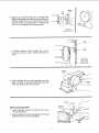
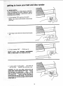
INSTALLING
PULLEY COVER
1_ Locate the pulley cover and one screw 1/4-20x
tL3/4".
2. Place pulley cover into position shown and fasten
with one screw. Do not overtighten.
SETSC
INSTALLING
HE×WRENCH
SANDING DISC PLATE
1. Locate sanding disc p_ate, sanding disc, one
setscrew 1/4.20xl/4
inch, and a 1/8 inch hex
wrench,
2. Just start screw into threaded hole in sanding plate.
:
•
i•
: •
•
_ ;ii_ :,_:i
•!
SANDINGDISCPLATE S
i i i
10
""*--_
/
""
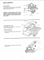
DRIVE
SHAFT
SANDING
PLATE
FLAT
3N SHAFT',
/
3 Alignflaton shaftwithsetscrewin sandingplate
Slidesandingplateontoshaftuntilplatesurfaceand
shaftarenearlyflush Donotallowshaftto extend
out past surface of sanding ptate or damage may
occur to your sanding disc during operation
GUARD NOT
SHOWN FOR CLARITY
J
\
HEX
WRE_4OH
/
SET
SCREW
4 To tighten setscrew, reach through hole in top of
pulley cover with hex wrench Tighten setscrew very
firmly
SECTIONOF
PULLEY COVER
REMOVED FOR
PICTURE CLARITY
I
I
IIII
SANDING
PLATE
5. Locate sanding disc and peet backing from disc.
Align perimeter of disc with plate and press disc
firmty into position all the way around,
n
nl,i
i!l
u
_u ul nnl,i
WRENCH
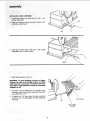
BACKSTOP
INSTALLING
BACKSTOP
LOCK BOLT
.,.,
BACKSTOP
1. Locate backstop, hex.bott 1/4-20xl/2
1/4 inch flat washer.
inch, and a
2 Hold backstop into position and fasten with bolt and
washer as shown Do not overtighten
11
lull
i
i
bolt
among loose _arts.
ROD
insert rod in base as shown, leaving 5 inches of rod
extending outside base,
BASE
.........
i
3. Install bolt in base (align a flat side of rod to bolt)
and tighten with 1/2 inch wrench.
I
I
I
II
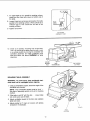
4. Slide table assembly onto rod.
WARNING: To avoid trapping the work or fingers
between the table and sanding surface, the table
edge should be a maximum of 1/16-inch from sanding surface. Table assembly should be completely
engaged on rod.
5. The table must be adjusted so it is parallel to the
sanding surface and no further away from the sanding surface than 1/16".
\
6. To adjust the 1/16" gap, slide the table assembly
forward on the rod and tighten the table assembly
lock knob.
TABLEASSEMBLY
ROD
\
TABLEASSEMBkY
LOCK
KNOB
12
7. To adjust table so it is parallel to sanding surface,
locate two allen head set screws on bottom side of
the table,
ALLEN HEAD
8. Loosen these two set screws and position the table
parallel to the sanding surface. (There should be a
minimum gap of 1/16" across the full face of the
sanding surface,)
9, Tighten set screws,
VIEW SHOWING
UNDERSIDE OF TABLE
10. There is an auxiliary mounting hole in the base.
This is for mounting the table when the belt is used
in a vertical position by moving the complete rod/
worktable assembly and table positioning bolt_
Note and follow the above WARNING for table
clearance,
AUXILIARY
MOUNTING
TABLE
HOLE
POSITIONING BOLT
TABLE ASSEMBLY
LOCK KNOB
iii
SQUARING TABLE ASSEMBLY
WARNING: To avoid injury from accidental start,
make sure t0ol is unplugged before aligning.
1, Using a combination square, check the angle of the
worktable with the disc.
NOTE: The combination square must be "true" -See start of assembly section on Pg, 6 for checking
method,
2. If the table is not 90 ° with the disc •.,
lock knob screw and tilt table.
3, Adjust worktable
table lock knob.
loosen table
square to the disc and retighten
4, Adjust pointer to 0° mark on trunnion with phillips
screwdriver if necessary.
TABLE
POSmONtNG
BOLT
/
I
TABLE
LOCK :KNOB
13
TRUNNION
assembly
NOTE: This unitcomes with the sanding bert installed.
DIRECTIONAL
ARROW
REPLACING THE SANDING BELT TENSIONING AND TRACKING
DRIVEPULLEY
\
WARNING: To avoid injury from accidental start,
turn switch "OFF" and remove plug from power
source outlet before removing or installing sanding
belt. Use only Sears recommended sanding belts.
See Sears Catalog.
\
BANDINGBELT
\
On the smooth side of the sanding belt you will find a
"directional arrow." The sanding belt must run in the
direction of this arrow so that the splice does not come
apart;
IDLERPULLEY
1. Slide tension knob to the right to release the .belt
tension.
TENSION
KNOB
2. Place the sanding belt over the pulleys with the directional arrow pointing as shown. Make sure the
belt is centered on both pulleys.
iii
ON.OFFSWITCH
i
3. Slide tension knob to the left to apply belt tension.
4. Plug in the power cord. Turn switch "ON" and immediately
........
OFF, noting _f the be It tends to shde
" off
the idler pulley or drive pulley. If it did not tend to
s idet off, it is "i'RACKING properly.
TENSION
KNOB
5. If the sanding belt moves toward the disc. turn the
tracking knob counterclockwise 1/4 turn.
6. If the sanding belt moves away from the disc. turn
the tracking knob clockwise 1/4 turn.
7. Turn switch "ON" and immediately "OFF" again, noting belt movement. Readjust tracking knob if necessary.
TRACKING
KNOB
14
getting to know your beat and disc sander
WARNING: To avoid injury from accidental start,
_urn switch "OFF" and remove plug from power
Jource outlet before making any adjustments.
BACKSTOP
LOCK
BOLT
SANDING
PLATE
SANDING
DISC
1
I
BACKSTOP
2
BELT
TABLE
LOCKING
BOLTS
BELT
i
BELT
TABLE
3
TRACKFNG
KNOB
SANDtNG
4
TENSION
KNOB
/
WORKTABLE
ASSEMBLY
TABLE
SUPPORT
ROD
PULLEY
COVER
9
BELT
TABLE
STOP
MOUNTING
HOLES
ON-OFF
SWITCH
8
AUXILIARY
MOUNTING
HOLE
TRUNNION
BASE
I
(WORKTABLE)
7
TABLE
POSITIONING
BOLT
1. Backstop,
belt.
6
1ABI L
ASSEM_I Y
5
TABLE
LOCK
KNOB
; OCK
KNOTd
5. Table Lock Knob . . . Loosening knob allows the
worktable to be tilted for bevel sanding (Scale on
tabfe trunnion).
,, Supports the workpiece on the sanding
2. Belt Table Locking Bolts... Loosening bolts allows
belt table to be raised to the vertical position.
6. Table Assembly Lock Knob • . . Locks the table
assembly onto the table support rod.
3. Tracking Knob.,.
Turning knob clockwise causes
sanding belt to move towards the disc; turning knob
counterclockwise causes sanding belt to move away
from the disc,
7. Table Positioning Bolt
base.
. . . Locks the rod into the
8, Auxiliary Mounting Hole . . Allows table assembly
to be mounted for end sanding on the belt side.
4. Tension Knob,,, Sliding knob to the right releases
the sanding belt tension; sliding knob to the left
applies belt tension.
15
getting to know your belt and disc
"
sande r
9. ON-OFF SWITCH
The On-Off Switch has a locking feature. THIS FEA-
1, To turn machine "ON" insert key into switch.
NOTE: Key is made of yellow plastic; locate in loose
parts bag.
2, Insert finger under switch lever and pull end of switch
out.
4. To lock switch in OFF position . . ,hold switch IN
with one hand., _ REMOVE key with other hand.
WARNING: For your own safety, always lock the
switch "OFF" when machine iS not in use.., remove
key and keep it in a safe place..,
also,,,
in the
event of a power failure (all of your lights go out)
turn switch off..,
remove the key and store it
remote from belt and disc sander, This will prevent
the machine from starting up again when the power
_ comes back on,
16
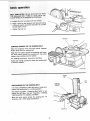
basic operation
BEVEL SANDING
_The worktable can be tilted from 0 ° - 45 ° for bevel
sanding. Loosen the table lock knob and tilt the worktable to desired angle as shown.
WARNING: To avoid trapping the work or fingers
between the table and sanding surface, the table
should be repositioned on the table support rod to
retain a maximum of 1!16-inch distance between
disc and table.
TABLE
SUPPORT RO0
BELT TABLE __..,,..
POSITIONING
WRENCH _C_.,p_
BELT TABLE
G a_l T_
Two bett table locking bolts lock the belt tabte in a
vertical or horizontal position,
Y
%
To adjust vertical position:
.
J
a, Remove the backstop.
b, Loosen the two belt table locking bolts using a 1/2inch wrench.
,,,,,.,=,'=
I
ii
'1
1,1,11
i
, i,lU
,i,_rrll
c. Position belt tabei vertically as shown and tighten
the two bolts.
t7
I tl
I
I................
It
Ul,l,,,=
J=
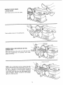
BELT
TABLESTOP
a.Loosen,the locknutusinga 314-inch
wrench.
b. Placea levelon the abrasivebelttableandusing
a 3/4-inchwrench,
screwthestopboltinoroutuntit
thebelttableis level,
c. Tightenthelocknut.
--
WRENCH
BACKSTOP
\
SURFACE SANDING ON THE SANDING BELT
WORKPIECE
Hold the workpiece firmly with both hands, keeping
fingers away from the sanding belt.
Keep the end butted against the backstop and move
the work evenly across the sanding belt. Use extra
caution when sanding very thin pieces.
For sanding long pieces, remove the backstop.
Apply only enough pressure to allow the sanding belt
to remove material.
SANDINGBELT
SANDING
BELT
WORKTABLE
ASSEMBLY
END SANDING ON THE SANDING BELT
It is more convenient to sand the ends of long workpieces with sanding belt in a vertica_ position.
See "Basic Operation - Positioning Belt Table" for adjusting the belt table, and see "Assembly - Installing
Table Assembly" for adjusting worktable.
Move the work evenly across the sanding belt. For
accuracy, use a miter gauge (accessory),
WORKPIECE
18
j
TABLE
BELT
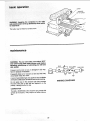
,_SANDING CURVED EDGES
DURVED EDGES
Sand inside curves on the idler pultey,
Sand outside curves on the sanding disc.
, i,,1[
!ll,ii
,,
, ...............
ii
ii, ......................
[
,i,
__
!l
MITERGAUGE
SANDING SMALL END SURFACES ON THE
SANDING DISC
Move the work across the center to the left side of the
face of the sanding disc. For accuracy, use a miter
gauge (accessory).
i,iii
,
COMBINATION
SQUARE
NOTE: Use a combination square to square the miter
gauge to the face of the disc (combination square must
be "true" -- See Start of Assembly section on page 6
for checking method). If it is not square, loosen the
miter gauge knob and move the miter gauge slightly
until it is square. Without moving the miter gauge,
tighten the knob securely.
I
19
be hazardous.
The table may be tilted for beveled work.
maintenance
WARNING: For your own safety, turn switch "OFF"
and remove plug from power source outlet before
adjusting, maintaining, or lubricating your belt and
disc sander.
BLACK
M
JUMPER _,,_,,,=or-OOD
/ RED t._aYt/ BLACK
SWITC._"L:: "
f power cord s worn or cut, or damaged in any way,
haVe t replaced immediately.
Frequently blow out or vacuum out any dust that may
accumulate inside the motor.
A coat of automobile-type wax applied to the worktable
will make it a little easier to feed the work while finishing.
WIRING
Do not apply wax to the abrasive belt table because
the belt could pick up the wax and deposit it on the
pulleys, causing the belt to slip.
LUBRICATION
The BALL BEARINGS in this machine are packed with
grease at the factory. They require no further lubrication.
....
:
:
:
20
:i !_:,: _i::_i_iii,_
:i,i_
:ii_i
ii_ii!i_i!i_'!_!_:!_i_ii:!::i:i:,ii
i_i:
i_: i _
DIAGRAM
trouble
shooting
WARNING:
For your own safety, turn switch
and remove plug from power source outlet
trouble shooting your sander,
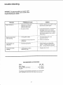
TROUBLE
,.,,,,,
,,,J ,,
Motor will not run,
PROBABLE
, , ,,
i
,
,,,,,.,IL
i,,, ,,,,,,,
1. Defective
Defective
Defective
2. Burnedout
Machine slows down
when sanding.
"OFF'"
before
CAUSE
REMEDY
.,
, ,L
On-Off switch.
switch cord.
switch box.
, '",",,,.'_
,,, .....
1. Replace defective parts before using
belt and disc sander again.
motor.
2. Consult Sears Service. Any attempt
to repair this motor may create a
HAZARD untess repair is done by a
qualified service technician. Repair
service is available at your nearest
Sears Store.
I. Timing belttootight.
1. Decrease belt tension, see
Assembly Section.
2. Applying too much pressure to
workpiece.
2. Ease up on pressure.
Sanding Belt runs
off pulleys.
1. Nottracking properly.
Wood burns while
sanding,
1. Sanding disc or belt is
glazed with sap.
Adjust tracking, see Assembly
Section, "Replacing the Sanding
Belt -- Tensioning and Tracking"
1. Replace disc or belt.
,,,,,,
RECOMMENDED
,,,,,
i
n l
ACCESSORIES
ITEM
CAT. NO.
Miter Gauge ........................
Sanding Belts and Discs ............
Leg Set ............................
9--24214
See Catalog
9--22244
The above recommended accessories are current and
were available at the time this manual was printed.
2t
i
-
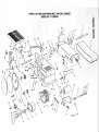
PARTS
LIST FOR CRAFTSMAN
BELT AND DISC SANDER
MODEL NO. 113.226423
7
4
/
5
67
\
66
8
/
1
lO
Green
Ground Leac
,77!
I7
\
18
\
\
41
38
44
33\
_q
29
28
_
i
25
3O
29
24
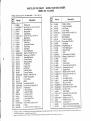
PARTS
LIST FOR CRAFTt "AN BELT AND DISC SANDER
MODEL NO. 113,226423
Always order by part no. and description -- not by key no.
Key
No.
Part No.
1
2
3
4
5
813909
STD502502
805642-6
814101
813915
Pulley-Drive
*Screw-Set, Hex. Cup 1/4-20x1/4
Ring-Retaining
Bearing-Bail
Cap-Bearing
6
STD511002
*Screw-Pan
7
8
9
10
11
t2
13
14
15
16
17
!8
19
20
21
22
23
24
25
26
27
28
29
30
31
32
33
34
35
36
37
38
39
813920
814110
813913
813948
813921
813911
814586
STD551025
STD522505
814045
814111
813918
813919
813912
813910
814596
813947
STD551025
814103
814108
814109
STD551208
STD510805
169123-10
814049
63837
803709
62442
814071
60256
STD510602
814589
809169-4
Shaft-Drive
1-Belt-Sanding
Table, Belt
Spring-Belt Tension
Screw-Stop
Stop-Back
Grommet-Rubber
*Washer 17/64x9/16xl/16
*Screw-Hex 1/4-20xl/2
Base-Belt Sander
Sleeve-Rubber
Bearing-Sleeve
Pulley-Idler
Guide-Drum
Shaftqdler
Washer, Wave
Spring-Tracking
*Washer 17i64x3i4x1 ll 6
Knob-Tracking Adv.
Cord w/plug
,Motor
*Lockwasher Ext N8
*Screw-Pan Cross 8-32x112
Relief-Strain
Housing-Switch
Lead Asm-Black
Connector-Wire
Switch-Locking
Panel-Switch Trim
Key-Switch
*Screw-Pan Cross 6-32xt/4
Relay
Screw-Pan, HD TY T8-32x1-1/4
•
•
t
Description
Cross
Key
NO,
Part No.
40
41
42
43
44
45
46
814669
814105
8t4002-1
814739
STD512515
813917
814107
47
814106
48
49
50
5t
52
53
54
55
56
57
58
59
60
6t
62
63
64
65
66
67
68
69
70
7t
72
73
74
75
76
--
STD523107
814069
STD58!025
814090
814096
814091
805466-2
STD55103t
814093
814089
814094
8 ! 4932
STD5512t0
814140
STD551010
STD523115
814088
814362
813916
161255-6
STD522510
STD502505
STD541025
814929
STD511007
813914
STD541250
30505
STD551 ! 25
SP500t
5O7303
10-24xl/4
Any Attempt To Repair This Motor May Create A Hazard
Standard
Hardware
items -,,, May Be Purchased
Locally
Stock Item _ May Be Purchased
Through The Hardware
Unless
Repair
Department
Is Done By A QualFied
Of Most Sears
Service
Retail Stores
Technician
Or Catalog
Order
Repair
Houses
Description
Washer, Rubber
Pulley-Timing Belt
Belt-Timing
Cover-Pulley
*Screw-Pan Hd 1/4-20xl -3/4
Plate-Sanding
tDisc-Sanding
Pulley-Timing Belt
*Screw-Hex 5116-18x I
Rod-Motor
*Ring-Retaining 1/4
Rod-Table Support
Support-Table
Knob
Screw-Hex 5116-18x9/16
*Washer 21/64x9i16xli16
Trunnion
Pointer
Table-Sander
Screw-Soc Cap 10-32xt/2
Lockwashe r Ext # l 0
Support-Pivot
*Washer 13/64x7/16x t/32
*Screw-Hex 5/16-18x 1- 1/2
Pin-Pivot
Knob-Belt Tension
Lever-Belt Tension
Nut-Lock 1/4-20
*Screw-Hex 1/4-20xl
*Screw-Set Hex Cup 1/4-20xl
*Nut-Hex 1/4-20
Cap, Rubber
*Screw-Pan Cross 10-24x3/4
Support-Bearing
*Nut Hex Jam 1/2-13
WRENCH HEX "L"I/8
Lockwasher 1/4
Owners Manual (Not Illustrated)
Bag of Loose Parts (Not {llustrated)
Service
Is AvaiJable
A_ Your Nearest
Sears
Store
BELT AND DISC
SANDER
SERVICE
MODEL NO.
113.226423
HOW TO ORDER
REPAIR PARTS
Now that you have purchased
your Belt
need ever exist for repair parts or service,
Service Center and most Sears, Roebuck
to provide all pertinent facts when you call
& Disc Sander should a
simply contact any Sears
and Co. stores, Be sure
or visit.
The model number of your Belt and Disc Sander will be found on a
plate attached to your sander on the back side of the base.
WHEN ORDERING
REPAIR
LOWING INFORMATION:
PARTS,
ALWAYS
GIVE
PART NUMBER
PART DESCRIPTION
MODEL NUMBER
113.226423
NAME OF ITEM
Belt And Disc Sander
THE
FOL-
All parts listed may be ordered from any Sears Service Center and
most Sears stores. If the parts you need are not stocked iocalty, your
order will be electronically
transmitled
to a Sears Repair Parts Distribution Center for handling.
,=,
Sold
PART
t'40
SP500t
by
SEARS,
ROEBUCK
,=l H,= =H ii
AND
FORM
NO
=
CO.,
SP500t-3
i
Chicago,
,q,l=== =
IL.
60684
U.S.A.
PRINTED
!N U S A
!!'86