1
OWNERS
MANUAL
MODEL NO.
917.252492
Caution:
Read Rules for
Safe Operation
and Instructions
Carefully
8 H.R
30" SLEEVE HITCH
T I L LER ATTACHMENT
Assembly
Installation
Operation
Repair Parts
Sears, Roebuck and Co., Chicago, tL 60684 U.SA
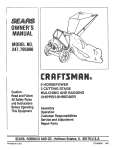
CONGRATULATIONS
on your
purchase
of a Sears 8 HP
Tiller Attachment.
_t has been designed, engineered and manufactured
to give you the best possible dependability
and performance.
Should
you experience
any problem
you cannot
easily remedy,
please contact
your nearest Sears Service Department,
the proper
They
tools
have competent,
well-trained
to service or repair this unit,
Please read and retain
this manual,
technicians
The instructions
you to assemble
o_erate
and maintain
Always obse_ve the
RULES FOR SAFE
will
MQDEL
NUMBER
SERIAL
NUMBER
THE MODEL AND SERIAL NUMBERS WILL BE
FOUND ON THE MODEL PLATE ATTACHED TO
THE RIGHT HAND SIDE OF THE TRANSMISSION
(FIG. 1)_
and
enable
your Tiller properly
OPERATION",
LIMITED
YOU SHOULD
RECORD
BOTH MODEL AND
SERIAL NUMBERS AND KEEPIN ASAFEPLACE
FOR FUTURE REFERENCE,
WARRANTY
ONE YEAR WARRANTY
For one year from the date of purchase,
when this attachment
is maintained,
tuned up according
to the operating
and maintenance
instructions
in the owner's
will repair free of charge any defect in material
or workmanship,
This warranty
excludes tine(s), spark piL_,;air"cleaner
and become worn during normal use,,
If the tractor attachment is used for commercial
only thirty days from the date of purchaser
and belt(s)
which
lubricated, and
manual, Sears
are expendable
or rental purposes, this warranty
parts
applies for
WARRANTY SERVICE IS AVAILABLE BY CONTAC_rING THE NEAREST SEARS SERVICE
CENTER/DEPARTMENT iN THE UNITED STATES° This warranty applies only while this product
is in use in the United States,
This warranty
gives
from state to state,
you specific
legal
rights,
and you
Sears, Roebuck and Co., D!698-731A,
-2_
may also have other
rights
which
Sears Tower, Chicago, IL 60684
vary
RULESFORSAFEOPERATION......................................................
BELOW
ASSEMBLYINSTRUCTIONS................................................................
4
OPERATIONINSTRUCTIONS................................................................
5
MAINTENANCEINSTRUCTIONS
............................................................
6
REPAIRPARTS.........................................................................
RULES
WARNING:
This unit
covered, brush,,covered
local or state laws
is equipped
with
or grass-covered
(if any)
In the State of California
have similar laws, Federal
17
I., Know the
OWNER'S
controls
and
MANUAL.
FOR
SAFE
an internal
combustion
land unless the engine's
If a spark arrester
is used, it should
how
to stop quickly
READ
engine
exhaust
your tractor
and
to operate them
Tiller
with°
is disen-
be sure Tiller
clutch
13
14
5. Before
engine,
11. Watch
12
in tines.
t&
gaged and tines are c_ear.
Make sure of your footing
and stand clear of tines when
starting engine
7_ Do not run engine
indoors
because the engine exhaust
fumes
contain
carbon
monoxide,
which
is a tastefess,
odorless, deadly poison°
84 Check fuel supply
before each use, Never remove the gas
6.
in effective
working
order
by the operator
ways be handled with extreme care
Stop tractor,
disengage Tiller
Attachment
chJtch
Tiller and tractor
engines. Shift tractor
to neutral
for traffic
when
crossing
or near roadways,
Always disengage Tiller clutch, and stop engine when traveF
ing to and from field or when not tilling,
Lift Tiller
Attachment
out of the ground
when turning
corners.
Do not put tractor
in reverse gear while Tiller
is in the
ground.
Keep all nuts, bolts and screws tight in order to be sure
that the tractor
and attachment
are in safe working
condition
Be sure the brake and all powered
attachment
controls
are always in proper adjustment
and repair. Check
the attachment
and engine mounting
bolts at frequent
intervals
for
proper
tightness
Before
performing
any
maintenance,
always disengage
the power to attachment,
set the parking
brake,
shift
into neutral,
shut off the
engine, make absolutely
sure the Tiller
Attachment
and
alt moving parts hove completely
stopped,
remove ignition
key, disconnect
the spark plug wire from the spark plug,
and keep it away from the plug to prevent
injury
or accidental
starting,
The only exception
to this rute is car,,
buretor adiustment
cap or fill the gasoline
tank when engine is running
or
while it is hot
When filling
the fuel tank, leave space for
expansion;
do not fill it to the brim and keep in mind
that the heat of the sun can cause the gasoline to expand
Wipe off any spilled
gasoline
before
starting
the engine.
Remember,
gasoline
is highly
flammable
and must
al9
and should not be used on or near any unimproved
forestsystem is equipped with a spark arrester meeting applicable
be maintained
THE
3. Keep children and pets a safe distance away
4_ Clear work area of objects which might be caught
the
OPERATION
the above is required
by law (Section 4442 of the California
Public Resources Code). Other states may
laws apply on federal lands See your Sears Authorized
Service Center for spark arrester
Refer to page
2. Do not allow children
to operate
Attachment
Do not allow
adults
out proper instruction,
starting
10
16
and stop
position,
set parking
brake
and remove
ignition
key before leaving
operator
s posrt_on.
10, Never stand near tines or work
on tines when engine is
running,
Keep the engine free from accumulations
of grass, leaves
or excessive grease, as these accumulations
are combustible
and could result in a fire Always keep your Tiller Attach.,
moot in good operating
condition
and make sure that alf
shields, guard p|ates and all other protective
devices are in
place Give your Tiller Attachment
the regular maintenance
it needs and have a competent
serviceman make a thorough
inspection
of it at least once a year
PRECAUTIONS
IT MEANS
-.. ATTENTION!
BECOME
LOOK
FOR THIS SYMBOL
TO POINT OUT IMPORTANT
YOUR SAFETY
IS INVOLVED.
-3-
ALERT!
SAFETY
ASSEMBLY
When
R H
(Right
Hand)
or
LH
(Left
Hand)
means from a position
behind the steering wheel
seated on the tractor seat and facing forward.
RETAINER
SPIRING
are used
it
as if you were
NOTE:
TILLER
REMOVE
MOWER DECK BEFORE
ATTACHMENT
TO TRACTOR.
Remove
Tiller
NOTE:
IF
SLEEVE
PARTS.
HITCH,
YOU
IF YOU MOUNT
MOUNTING
RIVET_
and bag of parts from
YOU
ARE
carton
MOUNTING
MAY
YOUR
YOUR
TILLER
TO
A
DISCARD
THE
BAG
OF
NEW TILLER
TO A MAN-
UAL
3 - POINT
HITCH,
YOU WILL
NEED THE BAG OF
PARIS
SEE YOUR
SLEEVE/3.
POINT
HITCH
ADAPTER
OWNERS
MANUAL
FOR INSTRUCTIONS
TO INSTALL
THESE PARTS
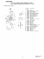
OIL
FILL
PLUG
1
GAUGE
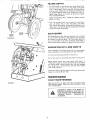
Place Tiller on level ground
up to it for assembly
so that
can be backed
]
WHEELS
TILLER
FORMING WILL
THE
FIGURE
Tractor
I
FOLLOWING
BE HEAVY
WHEN
STEP°
PER-
Adjust Tiller Gauge Wheels so that engine is level (Fig 1),
a, Remove Retainer Spring from drilled Rivet,
b, Remove Rivet and adjust Gauge Wheels up or down as
required
to level Tiller
Replace
Rivet
and Retainer
Spring,,
NOTE: BE CAREFUL
NOT TO ALLOW
DIRT
THE
ENGINE
OR TRANSMISSION
WHEN
OR ADDINGOILOR
FUEL
3,
IMPORTANT:
to Fig. I
was filled
Plug Hole
let can be
@
No,
4,
30
Check
oil
level in Tiller
Motor
IMPORTANT:
Oil
(SC, SD or SE),
ENGINE
ATTACHING
IS
Transmission.
Replace
SHIPPED
TILLER
Oil
WITHOUT
TO
1, Install one or more wheel Weights
sure good traction
when operating,
Tire chains can
wheel weights,
2
be used
in
tire
44 Assemble
Refer
pressure
in Tires
Sleeve Hitch
to
OIL
of;
the
7.
or
in
f_ont
See Hitch
2
8.
to in:
addition
to,
of the tractor,
owners
manual
owners
manual,
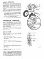
with
Lower Hitch Assembly
and slide Hitch Yoke of Tiller (Fig
2 - Inset) over Hitch Tube of Sleeve Hitch so that the Hitch
Pin Holes line up,
Insert
Yoke
FIGURE
Fill
Oil (SC, SD'
Refer to Fig.
5, Adjust
Stabilizer
Bolts so that ends are about flush
rear of Hitch Bail (Fig. 2 * Inset), Leave Nuts loose,.
6
Plug:
TRACTOR
See tractor
to Tractor.
Fill
to each rear wheel
place
Install two front end weights
This will aid steering control
3o Check
TO ENTER
CHECKING
for location
of Oil Fill Plug,, The Transmission
at the factory
and oil should be to level of Filler
Tiller must be level, if oil needs to be added TiF
laid on its side to fill Transmission,
Use S.A,E_
Engine Crankcase
with SA.E
NO, 30 Motor
or SE)Capacity
is 1 - 1/2 pints (24 ounces)
1 - Inset for Oil Fill Tube location,.
TINE
SHIELD
|
Hitch
(Fig
Pin
until
2- Inset),
it extends
Insert
Retainer
from
bottom
Spring
into
of
Hitch
Hitch
Pin,
Tighten
both Stabilizer
Bolts against the Hitch Yoke until
there is no looseness at the hitch point,
(The
Frame As _
sembly does not swing sideways relative to the Hitch Bail
(Fig. 2),, Be sure the Frame
Assembly
is perpendicular
(square) to the centerline
(direction
of travel} of the Trac'
tor,, This can be determined
by measuring
the distanc_
bebNeen the edge of Tine
the rear tires° This distance
Shield (Fig, 2) and the back of
should be the same on the R,H,
and L.H sides within
on the Stabilizer
Bolts_
inch.
1/2
Securely
tighten
the
Nuts
NOTE:THESTABILIZER
BOLTS
SHOULD
BELOOSENED
BEFORE
REMOVING
THETILLERFROM
THETRACTOR.
THISW1LLMAKEIT EASIER
TO REMOVE
THEHITCH
PINANDTOLINEUPHITCHPINHOLESWHEN
INSTALL,,
INGANOTHER
ATTACHMENT
tF TRACTOR
ISTO BE
USED
WITHOUT
A REARATTACHMENT,
THESTABILIZERBOLTS
SHOULD
BESECURED
BYTIGHTENING
THE
NUTS(FIG,2- INSET)
/
LIFTCONTROL
LEVER
OPERATOON
READ
THE "RULES
FOR SAFE OPERATION"
CAREFULLY
BEFORE
OPERATING
YOUR
TILLER.
THE
ENGINE
HAS
BEEN SHIPPED WITHOUT
OIL,
FIGURE
3
1
Be sure that you have complied
with steps 3 and 4 at top of
page 4,,
2, F_II Fuef Tank with
clean, fresh, unleaded
gasoline. Capacity
is 1 gallon.. WARNING:
DO NOT USE GASOHOL,
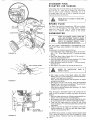
3.
RAISE TILLER:
a,, MANUAL
HITCH
{Fig
. Pu!l rearward
b,, ELECTRIC
ASSIST
tion¢ move Power
the _LJP_ position
4
Disengage
5,
Move Tiller
5- Inset),
6
7
Tine
Place Tiller
(Fig, 5),
Clutch
Engine
Engine
- With
Assist
Control
Lever
Lever (Fig,
Choke
in "ON"
pos]-
on dashboard
to
4),
Lever to
Throttle
Key
located
Lever
"FULL
to
CHOKE"
about
1/2
(Fig
"ENGAGED"
POSITION
throttle
-=
)
FIGURE 4
Grasp Starter Handle (Fig 5), pull cord slowly until starter
clutch engages, then pull slowly until resistance of compression is felt, Allow starter cord to recoil and again pull out
slowly
until
starter
clutch
engages
Pull sharply,,
Do not
slowly
keeping
After engine starts, move Choke Lever to _NO
position
as engine warms up (Fig 5 - Inset),
9,, Move
I0,
Ignition
Switch
allow rope to snap back, Rewind
starter handle at all times,
8
on Lift
3),
Tiller
Engine
Throttle
STAND
CLEAR
Lever
to
"FAST"
OF ROTATING
hold
%
of the
CHOKE"
position
TINES.
1
Engage Tine Clutch
Lever (lever pulled up - Fig 4), Disengage and engage several times to check
the clutching
action
of the belt,, If it is not clutching
properly,
refer to
Belt Adjustment
page 9,
11, To stop Tiller
4) and move
and engine, disengage Tine
Throttle
Lever to "STOP"
I12
CHOKE
NO
CHOI
CLEANER
TINE CLUTCH
LEVER
,,01._
POSITION
FULL
_
CHOKE
AIR
CLEANER
Clutch Lever (Fig
position
(Fig 5)
'" FAST"
POSITIOt
_
TILLING
The most efficient
tillage
is obtained
when Tiller Engine is
operated at full throttle.
When Tiller Engine is lightly loaded,
raise Gauge Wheels to increase
tilling depth
If Engine seems
to be overloaded
or stalls
out, lower
Gauge
Wheels
for
shallower
tilling,
;STARTER
!HANDLE
Operate
Tiller
Engine at full throttle
and operate
tractor
in
slowest forward
speed, with
tractor
engine at idle speed or
"ust above idle
You will soon learn the proper combination
_f tilling depth and speed for good tillage
FUEL
TANK
Soil conditions
will
determine
how deep TilLer
can penetrate on the first pass, In extremely
hard ground, several passes
may be necessary to till to a depth of 5 inches while in soft
ground, Tiller may penetrate
to a depth of 5 inches in the first
pass
- 5 -"
FIGURE
5
TILLING
DEPTH
The tilling
depth is controlled
6) and to some extent
by
by the Gauge Wheels (Fig
the Adjustable
Link Sleeve
(Fig 7).. When deeper titling is required,
must be raised
Wheels must be lowered
RETAINER
L_RING
ing.
Remove
Retainer
Spring
Adjust
Gauge Wheels up
Rivet and Retainer Spring
NOTE:
EACH
HOLE
WHEELS
1 INCH
2,
from
Drilled
or down
WILL
GAUGE
Rivet
as desired
RAISE
OR
(Fig
6).
end reptace
LOWER
GAUGE
Tiller can be leveled from front to rear by turning
Adjust..
able Link
Sleeve (Fig
7). The Adjustable
Link
Sleeve
also controls
tilling depth
Shortening
the Adjustable
Link
Sleeve and Lift Links will decrease
ening will increase tilling depth
GAUGE
WHEEL
the Gauge Wheets
for shallower
tilt-
tilling
depth
and length-
CULTIVATING
WHEEL
Set Gauge Wheels so that Tiller wilt penetrate
soil to a depth
of 2 to 3 inches, Place Rivet in the second or third hole from
FIGURE 6
the bottom
to attain this depth
The Tiller Engine should be
run at full throttle
ex:'ept when cultivating
small plants, a
slower engine speed is necessary to prevent burying the plants
OPERATION
DO'S
AND
DON'TS
/
LIFT
Always
disengage Tine Clutch
when traveling
to or from field
LINK
Lift
Tifier
Do not
ADJUSTABLE
LINK SLEEVE
put
out of the ground
tractor
turning
corners.
Tiller
is in the ground
seat, stop tractor
shift
tractor
tc
throttle
down and stop tractor engine,
set Parking
Brake, remove
Tine Clutch
Lever, throttle
lower Ti!ler to ground.
LIFT
when
in reverse gear while
Before
leaving
tractor
NEUTRAL
posit=on,
7 ,, 112"
Lever (Fig 4) and stop engine
(garden) or when not tilling.
Ignition
down
Disconnect
Spark Plug Wires before
repairs or to remove debris in tines.
Key
and
making
and then disengage
stop Tiller
Engine,
any adjustments,
MAINTENANCE
DAILY
FIGURE 7
MAINTENANCE
Make sure all Nuts are tight,
Cotter
Pins are spread and Retainer
Springs secured.
Observe all safety precautions.,
Keep
Tiller welt lubricate&
-6-
DISCONNECT
SPARK
PREVENT
ACCIDENTAL
PLUG
WIRES
STARTING
TO
BE-
FORE
MAKING
ANY
JUSTMENT
(EXCEPT
OR REPAIR°
INSPECTION,
ADCARBURETOR)
ENGINE
LUBRICATION
F_TE: BE CAREFUL
1dE ENG NE WHEN
NOT TO ALLOW
CHECKING
OR
:HECK
LEVEL
ENGINE
OrL
AFTER
DIRT
TO ENTER
CHANGING
OIL.
EACH
5 HOURS
OF
DPERAT|ONo
Several minutes
after stopping
3il Dipstick,
Remove
and read Oif Level
If
Dit until
"FULL"
mark is reached
UseS,AE.
Engine, check
necessary, add
30Motor
Oif
(SC, SD or SE_ NOTE:
0if Dipstick
Replace
DO NOT
OVERFILL
Engine
ENGINE
OIL
DRAIN
PLUG
CHANGE
OIL AFTER
FIRST
5 HOURS
OF OPERATION°
The best time to change Oif is at the end of a days operation.
when all dirt and foreign material are suspended in the hot Oil
1,
2
Drain Engine Oil by removing
the Engine Oil Drain Plug (Fig
81 and Oil Dipstick
(Fig, 8 * Inset)
Catch Oil in a suitable
container,
Replace Engine Oil Drain Plug
Refill
Engine
pints
_24 ounces)
CHANGE
with
OIL
Oil as stated
Replace
AFTER
EVERY
Capacity
TRANSMISSION
OF OPERATION.
OIL
25
1. Remove
HOURS
LEVEL
Wing
]L Wash Foam
Nut
AND
if engine
and Cover
Pro-Cleaner
PreoCleaner
Foam
Let Foam
CLEAN
more often
the exhaust°
2,, Remove
Foam
Paper Cartridge,
AFTER
EACH
110
Oil in this Tiller
be changed,
Oit
Pro-Cleaner
Pro-Cleaner
by
RE-OIL
runs
(Fig
in liquid
oil
rich,
FOAM
PRE-
and emits
_WING
sliding
it
detergent
and
overnight
up
and
off
the
and water,
thoroughty
FOAM
PRE-CLEANER
squeeze
for best results.
Squeeze
to
distribute
and
re-
7. Clean the Cover,
Install
Foam Pre-Cleaner
ble Cover and Wing Nut°
over
NUT
black
9).
in cloth
dry
6,. Saturate
with
engine
move excess oil.
8.
9
(with Tiller level), If
Oil (SC, SD or SE),
CLEANER
EVERY
5.
FIGURE
OIL
LEVEL
AFTER
FIRST
5
Remove Oil Fil{ P/ug (Fig. 8)° Oil
TRANSMISSION
OF OPERATION_
CLEANER.
smoke from
4, Wrap
dry.,
8
OF OPERATION.
NOTE:
It is not necessary to change the
Transmission_
if
for any reason,
it must
capacity is 1 - 1/4 quarts
AIR
FIGURE
LUBRICATION
Level must be even with this Plug Hole
necessary, add Oil, Use S.A,E
30 Motor
(same as engine)
Replace Oil Fill Plug
CHECK
HOURS
is 1 - t/2
Oil Dipstick.
25 HOURS
TRANSMISSION
CHECK
HOURS
above.
the
TRANSMISSION
OIL FILL PLUG
Paper
Cartridge,
Reassem-
EVERY
t00
HOURS-REMOVE
PAPER FILTER°
TAP
,LIGHTLY TO REMOVE DIRT; REPLACE IF NECESSARY.
/DO NOT OIL CARTRIDGE
OR USE PRESSURIZED
AIR
TO CLEAN
CARTRIDGE.
A DAMAGED
CARTRIDGE
WILL RESULT IN RAPID WEAR OUT OF THE ENGINE.
DO NOT RUN ENGINE WITH AIR CLEANER REMOVED°
-7-
CYLINDER
STARTER
FiNS
AiR
SCREEN
Keep engine clean of foreign matter
der Fins {Fig
10 -lnset)
and Air
clean to permit
proper
ventilation
air cooled engh]e
engine performance
and free air flow
and long life
WEAR
PRESSED
SAFETY
AIR
SPARK
SPARK
WIRE
is important
GLASSES
for proper
IF USING
COM-
PLUG
PLUG
AND
COVER_
THROTTLE
CONTROL
CARBURETOR"
at all times 13esure 'Jyli_
Screen (Fig
10) are kep_
Remember,
this is an
The Spark Plug should be changed every 100 hours of operalion,
or at the beginnina
of each tillage
season, whichever
comes first. Gap at 030"
(Fig. 11), Order the part number
tis_ed in the "REPAIR
PARTS"
section
of this maqual
CARBURETOR
WHEN
FOLLOWING
STEPS
LISTED
BE-
LOW, USE EXTREME
CARE
TO AVOID
CONTACT
WITH MUFFLER,
OR MOVING
PARTS
TO PREVENT
INJURY.
ALSO,
BELT GUARD
MUST BE IN PLACE,
DO NOT
MAKE
TORY
SETTINGS
TIONS.
;,r
FIGURE
UNNECESSARY
ARE
CORRECT
If adjustments
are needed
1
Speed Adjust Needle (Fig. 12) by turning clock) Close finger tight ONLY.
Forcing may cause
10
Close High
wise ( _
proceed
ADJUSTMENTS.
FACFOR MOST APPLICA-
damage,
2. Open High Speed Adjust
1/2 turns counterclockwise
as follows:
Needle
(f'_)
(Fig
12) by turning
1 -
3.
030-FEELER
GAUGE
Close Idle Adjust
Needle by turning
clockwise
(,'-_)
Close
finger tight ONLY.
Forcing may cause damage
4. Open Idle Adjust
Needle by turning
1 - I/4 turns countel
clockwise
(_"_).
5
Start
engine
_
SPARK PLUG"
_/__
Run engine
a few minutes
to warm
STEPS
8,
REFER 3 THRU
TO "OPERATION"
wise (f'_) until engine
Allow
several seconds
runs smoothly,.
between each adjustment
5,
]
for engine
to adapt to new setting.
7, With engine running
at full throttle,
adjust the High Speed
Needle 1/8 of a turn at a time clockwise
(,'-_) and counterclockwise
{f_,) until engine runs smoothly.
Allow
several seconds between each adjustment
to adapt
I
IDLESPEED
kDJUST
SCREW
ADJUST
12
PAGE
6. With
engine running
at Idle Speed, adjust
Idle Adjust
Needle I/8 turn at a time clockwise
(r_,) and countetclock-
FIGURE 1I
FIGURE
it up,
SPEED
NEEDLE
for engine
to new setting
After the engine is thoroughly
broken
ning), it may be necessary to readjust
follows:
in (2 or 3 hours of runthe engine Idle speed as
I.
Start the engine and warm up, following
recommended
procedures. Two to thzee minutes is sufficient
time,
2, With engine at Idle Speed, turn the Idle Adjust Screw slowly counterclockwise
{f_)
until the engine begins to falter,
3, Then raise the engine speed by turning
the Idle Adjust
Screw clockwise
(f-_ } until the engine holds a smooth constant speed,,
4. Check to see that the engine will accelerate
to full spee,
without
hesitation.
If it will not, open Idle Adjust
Needt.
1/8 turn counterclockwise
((_,).
CAUTION:
Never attempt
to change maximum
engine speed,,
This is preset at factory
and can only be changed by a qualified Sears Service Technician
who has the necessary equip- 8 _ menL
BELT
ADJUSTMENT
SHUT
FOLLOWING
OFF
ADJUSTMENT.
ENGINE
WHILE
MAKING
TINE CLUTCH
LEVER
(SET
SHEAVE
SCREW END)
The Clutch
is a belt-tightener
type. Belt should be just tight
enough
to prevent
slipping.
Over tightening
will reduce Belt
life. To tighten
Belt, remove
Retainer
Spring securing
BeltTightener
Link to Clutch Lever and Arm. Turn Link in a counterclockwise
(_"-'_ } direction
when standing
in front of Tiller,
one turn at a time, until
Belt no longer slips
Initial
adjustment should be such that a force of approximately
10 fbs. at
the end of the Lever is required
to engage the Clutch.
This
would be a heavy thumb pressure (Fig 13)
CAUTION:
BELT
REMOVED,.
REPLACEMENT
!.
Remove the
move Guard
2
Remove
3
install
(Fig
BELT GUARD
three
bolts
holding
Belt
Guard
to Tiller
Re_
old Be[t,
new
Belt so that
lower
side
of
Belt
is above
TINE
CLUTCH
LEVER
"ENGAGED"
POSITION
/ _ 7"_o.
SHEAVE
(SET SCREW END)
Idler
13) as shown
4
Adjust
Belt,
5.
Replace Belt
Belt Guard.
refer
to
Guard.
"BELT
Make
ADJUSTMENT"
sure all
moving
section
parts
will
clear
NOTE: IF IT SHOULD
BECOME NECESSARY
TO REMOVE THE ENGINE SHEAVE,
BE SURE THAT IT IS
REINSTALLED
SO THAT THE SET SCREW END IS TOWARD THE OUTSIDE (FIG. t3)o
"DISENGAGED'°\
POSITION
10 LB. (HEAVY
THUMB
PRESSUREI
STORAGE
Engines to be stored
ed of fuel to prevent
etor parts, fuel filter,
1
Drain
fuel tank
2.
Operate
engine
consumed,
over 30 days should be completely
gum deposits forming
on essential
fuet lines and tank°
draincarbur-
FIGURE 13
completely,
until
3, While engine is still
with fresh oil,
gasoline
warm,
in carburetoi"
drain
oil
from
is completely
crankcase,
Refill
4. Remove
spark plug. Pour one ounce (2 or 3 tablespoons)
of S.AoEo 30 oil into cylinder
and pull Starter Handle slowly several times to distribute
oil. Replace spark plug.
5
Clean dust, dirt and oil from Cylinder
Fins,
ing, Air Screen and entire Tiller (Fig, 10),
STORE YOUR TILLER
PROOF BUILDING.
INSIDE
Blower
Hous-
A DRY,WEATHER-
Sears, Roebuck and Co reserves the right to make any changes
in design or improvements
without
imposing any obligation
to
install the same upon its items heretofore
manufactured
\
\
-9-
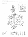
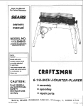
REPAIR
PARTS
TILLER
ENGINE
AND
ATTACHMENT--MODEL
NUMBER
917.25249_
TINES
13
_15
.16
18
22
25
_19
68
4
24
28
27
A
B
C
D
_
@44 @s2
E
F
G
45
@ 47
@)51
H
@
_o
J
40
@ 19
@ 47
@38
041
1_
-10-
L
49
4z
@_I
K
39
M
53
54
@38
@55
@
_)
39
56
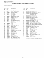
REPAIR
PARTS
TILLER
ENGINE
KEY
NO
NUMBER
917o252492
AND TINES
PART
NO
1
2
3
4
5
6
7
6923J
6924J
677A860
4379H
677A855
6922R
109856X
8
9
10
11
12
13
14
15
104867X
49|4H
8249R
6652H
6656H
624A12
2360J
19151116
16
17
t8
19
20
21
22
23
24
25
26
27
28
29
31
32
"33
34
35
36
37
ATTACHMENT--MODEL
12000015
6683H
4933H
19131414
4497H
626A430
634A726
106948X
8225R
8216R
4929H
3146R
626A401
8212 R
626A402
8224R
76020516
8905R
76020824
ST0523110
19131311
DESCRIPTION
Control Throttle
Bracket - Throttle Control
Hitch Yoke Assembly
Grip - Handle
Hitch Channel Assembly
Plate - Adapter
Engine 8 H P, Tecumseh-Modet No
143. 776012
Decal- lnstructlon_ Engine
Square Key 1/4 x 1 - 1/4
Engine Sheave
Belt Tightener Link
Adjusting Pin
ldfer Support Plate and Pivot
idler Arm
Washer t5/32 x 11/16 x 16 Ga
(0 - 2 as required}
*E.Ring
E-Ring
Idler Pulley
Washer 13/32 x 7/8 x 14 Ga
Retainer Spring
Lever and Arm
Belt Guard and Supports
Decal - Logo, Craftsman
V-Belt
Decal - Caution
Drilled Pan Hd Rivet 3/8 x 1 - 3/4
Retainer Spring
Tine Weldment- L H
Decal
Tine Weldment - RH
Tine Shield
Cotter Pin 5/32 x I
Spring
Cotter Pin 1/4 x I - 1/2
*Bolt - Hex 5/16 - 18 x 1Gr.. 2
Washer 13/32 x 13/16 x 11 Ga
-11-
KEY
NO,
PART
NO,
38
39
40
41
42
STD551137
STD541037
ST05231t5
STD54t031
157605!2
43
44
45
46
47
48
STD5225t0
STD551125
STD54t025
ST0623107
STD55t131
STD503103
49
50
51
52
53
54
STD523715
STD541237
STD55103t
11050500
74930632
STD535010
55
56
57
58
59
60
.61
62
63
64
65
66
67
68
69
o-.
ST0551150
STD541050
DESCRIPTION
*Lockwasher 3/8
*Nut-Hex3/8-16
UNC
*Bolt- Hex 5/16 - !8 x 1 _ 1/2 Gr. 2
*Nut-Hex5/16t8UNC
Hex Bolt with Seres Ext Lockwasher
5/16- 18 UNC x 3/4
*Hex Bolt 1/4 ..20 x 1
_Lockwasher 1/4
*HexNut
1/4-20UNC
*Hex Bolt 5/16 ..24 x 3/4
*Lockwasher 5/16
* Hex Forged Socket Headtess Set Screw
5/16 - 18 x 3/8 C P,
"HexBoit3i8-16x
1ol/2
*Hex Jam Nut 3/8 - 16 UNC
*Washer 11/32 x 11/16 x 16 Ga.
Lockwasher - Externat Tooth 5/16
Bolt- Hex 3/8 - 16 UNC x 2 Full Thd
_ Bolt - Sq Neck Carriage Short Shoulder
1/2 .. 13 UNC x t
* Lockwasher -. 1/2
"Nut-ASF
Hex 1/2 .. 13 UNC
73690600
4939M
6678H
Locknut 3/8 - 16 UNC
SpringRetainer
Bo_t ,. U
3457R
6665H
7796R
6782R
Extension.,
Lift Handle
Plate-U-Bolt
Lift Link., R,H
Swivet.
Lift Link
9204H
7795R
LoeknutLift Link,,
9773R
72250614
4777J
Bracket - Lever Stop
Bolt- Carriage 3/8- 16 x 1 - 3/4
Decal o 8 H P
105332X
109995X
Decal - Craftsman
Owners Manual
*STANDARD
HARDWARE..PURCHASE
1/2.20
LH
UNF
LOCALLY
REPAUR
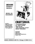
PARTS
TILLER
TRANSMISSION
ATTACHMENT--MODEL
NUMBER
917.252492
AND GAUGE WHEELS
t
\
L.............
6
/
15
16
A
B
39
_4o
C
D
(_ 42
E
F
G
@44
®43
e43
_)44
i
_35
_12_
7
REPAIR
PARTS
TILLER
TRANSMISSION
KEY
PART
NO,
NO
1
2
3
4
5
634A562
9135R
4929H
634A61
634A559
6
7
8
9
10
12
13
14
15
16
t7
18
2557J
4898H
19131311
73560600
3136R
4895H
9204H
4932H
4910H
3039R
4877H 1
624A56
19
20
21
24
26
27
28
2601 R
4870H
634A555
2600R
1370H
49! 2H
634A59
ATTACHMENT_-MODEL
NUMBER
917.252492
AND GAUGE WHEELS
DESCRIPTION
Transmission
Retainer Spring
Drilled Pan Head Rivet 3/8 x I -3/4
Gauge Wheel Sleeve and Brackets
Gauge Wheel Adjusting Shaft and
Bracket
Wheel
Shoulder Bott
Washer 13/32 x 13/16 x 11 Ga
Locknut 3/8 - 16 UNC Nylok
Needle Bearing
Needle Bearing
Lock Nut 1/2 - 20 UNF
Input Sheave
Oil Seal
Needle Bearing
Gear Case Shield L,H,.
Gear Case and Bearings L.H_ Half
(fnco Key No's 10, 12, 16& 20)
Gasket
Thrust Cap
Tine Shaft and Sprocket
Roller Chain
Thrust Bearing Race
Gasket
2nd Reduction Shaft and Gears
KEY
PART
NO,
NO
29
30
31
32
33
34
35
36
37
634A58
9858Mt
634A57
5855H
6672H
49t3H
t685H
t 3060400
624A57
38
39
40
41
42
43
44
45
46
4878HI
STD55! 137
STD54!037
STD55t13t
STD541031
7850H
STD551031
STD523722
17860524
47
48
49
STD523t07
STD523120
17850524
50
51
74780596
74760508
*STANDARD
-13-
DESCRIPTION
1st Reduction
Woodruff
Shaft
Key 3/t6
and Gears
x 5/8
input Shaft and Pinion
Relief Valve
Gear Shift
Gasket
Locknut
Pipe
Cover
5/16.
Plug
1/2
18 UNC
- 14
NET.
Gear Case and Bearings R.H_ Half
(Inc Key No's 12, 16 & 20}
Gear Case Shield
R,H,
* Lockwasher 3/8
*Hex Nut 3/8 ,,16 UNC
*Lockwasher 5/16
"Hex Nut 5/16,,18 UNC
Spacer
*Washer 11/32 x 11/16 x t6 Ga_
*Hex Bolt 3/8- 16 x 2 _ t/4
Hex Hd. RoH-Lok Thd. Forming
Screw 5/16- 18 x t - l/2
*Hex Bo_t 5/16- 18 x 3/4
*Hex Bolt 5/16- 18 x 2
Flat Hd, Slotted Rol1_Lok Thd
Forming Screw 5/16 .. 18 x t .. 1/2
Hex Bolt 5/16 - 18 x 6 Gr, 5
Hex Bolt 5/!6 - t8 x t/2
HARDWARE.,,PURCHASE
LOCALLY
REPAIR
PARTS
TILLER
8 H.P.
ATTACHMENT--MODEL
NUMBER
917.252492
ENGINE TECUMSEH--MODEL
NUMBER
143.776012
ENGINE
174 /
24
82A
189
.EPAIR
PARTS
TILLER
8 H.P.
ATTACHMENT--MODEL
NUMBER
917.252492
ENGINE TECUMSEH--MODEL
NUMBER
143,776012
ENGINE
KEY
NO
PART
NO
1
3
3A
3C
4
5
6
7
35385
27642
30968
32214
35319
27652
35326
650561
8
9
35372
34552
9
34553
9
34554
9A
9A
34329A
34330A
9A
3433tA
10
11
tl
11
17
27888
34332
34-333
34334
35373
18
19
2O
21
35374
650882
34O34
35375
22
23
24
25
33273A
650128
*35262
35376
26
27
33
35377
35319
30699C
34
35
36
37
38
39
40
41
42
43
30700
650494
29642
31845
30588A
30590A
29193
35378
33369
650836
49
50
51
52
53
54
55
56
29916
29826
29216
33454
29918
65O548
30322
650832
57
650833
56
59
60
66
66
34011A
3359O
33893A
27878A
27880A
67
34035
DESCRIPTION
KEY
NO
PART
NO
Cylinder (lnd
Nos 3, 4 Ef 5)
Plug, Pipe
Nipple, Oit drain
Elbow, Oil drain (45 degrees)
Seat, Oil
Pin, Dowel
Baffle, Blower housing
Screw,
Hex
washer
hd.
Dudock,
1/4-20 x 5/8
Crankshaft
Piston,
Pin 8- Ring Assy
(tncl, Nos.
9A, 10 8- 11) (StdJ
Piston, Pin 8- Ring Assy, (IncL Nos.
gA, 10 8- 11) (.010 oversize)
Piston, Pin 8- Ring Assy. (lncl. Nos
9A, 10 8- 11) (.020 oversize)
Piston 8- Pin Assy, (IncL Noo 10) {Std,)
Piston 8: Pin Assy. (Incl. No, 10) (,010
oversize)
Piston 8- Pin Assy. (Inc!. No 10) (.020
oversize)
Ring, Piston pin retaining
Ring Set, Piston (Std.)
Ring Set, Piston (.010 oversize)
Ring Set, Piston (,020 oversize)
Rod Assy., Connecting
(lncl, Nos
18
r_ 19)
Dipper, Oii
Screw, Connecting
rod
Lifter, Valve
Camshaft
(Mechanical
Compression
Release)
Extension,
Blower housing
Screw, Fil, hd, Sems, 10-24 x 1/2
Gasket, Cylinder cover
Cover Assy,, Cylinder (lncL Nos 26,
278-37)
Bearing, Cylinder cover
Seal, Oil
Rod Assy,
Governor
(incl, Nos 34 835)
Yoke, Governor
Screw, Fi!. hd Sems, 6-40 x 5/16
Ring, Retaining
Shaft, Governor
Spool, Governor
Washer, Flat
Ring, Retaining
Gear, Governor (tncL No. 3g)
Bracket, Governor gear
Screw,
Hex washer hd. thread forming, 10-24 x 1/2
Clamp, Governor lever
Screw, Hex washer hd., 10-32 x 3/4
Locknut,
Hex "Keps",
10-32
Lever, Governor
Washer, E.T. Lock
Screw, Hex washer hd., 8-32 x 5/16
Locknut,
Hex "Keps",
8-32
Screw,
Hex washer
hal. Powerlok,
1/4.20 x !-!1/16
Screw,
Hex washer
hdo Powerlok,
t/4-20 x t-3/16
Dipstick,
Oi! (Incl. No. 59)
"0" Ring
Tube, 0il filler
Valve, Exhaust (incl. No. 70) (Std.)
Valve, Exhaust (Incl
No, 70) (1/32"
oversize)
Valve, Exhaust (lncl No, 70) (Std)
67
34036
-15-
68
68A
69
70
76
77
78
79
80
8t
82
82A
83
95
96
97
98
99
100
10t
t04
105
106
107
108
108A
109
114
115
116
117
118
119
120
130
133
134
135
136
137
138
139
140
141
142
143
144
145
146
155
156
t57
158
159
159A
160
DESCRIPTION
Valve, Intake (inct No_ 70) (1/32"
oversize)
27882
Cap, Upper valve spring
34689
Seal Assy., Intake valve
27881
Spring, Valve
32561
Cap, Lower valve spdng
32589
Key, Flywheel
29443
Cllp, Wire
611090
Flywheel
650880
Washer, Lock
650881
Nut, Flywheel
650872
Stud, Solid State mounting
35135
Solid State Assy
610118
Cover, Spark plug
650814
Screw, Hex hd Seres, 10-24 x 1
35187
Wire, Ground
"34041
Gasket, Cylinder head
34030
Head, CyIinder
6021A Screw, Hex flange hd,, 5/16-18x 1-1/2
33536
Spark Plug (Champion
J-gC
or
equivalent)
650691
Washer, Flat
650727
Screw,
Special hex h& tapped,
5/!6-18 x 1-3/4
"27896
Gasket, Breather
28423
Body, Breather
28424
Element, Breather
28425
Cover, Breather
34696
Tube, Breather
32446
Grommet, Breather tube
650128
Screw, FiL hd, Sems, 10-24 x 1/2
29752
Nut 8- Lockwashar, 1/4.28
*33263
Gasket, Carburetor
35043
Tube, Carburetor
34707
Pipe, Intake
30088A
Screw, Fil, hd, Seres, I14-28 x I
650378
Screw, FiL hd, Sems, 5/t6-18 x %1/8
*27915
Gasket, Intake pipe
34833A
Housing, Blower
34664
Bracket Assy., Control (Incl Nos 134,
135 8" 138)
31342
Spring, Compression
650549
Screw, Fil, hd, 6,40 x 7/16
610973
Terminal Assy
650821
Screw, Hex washer hd. thread cutting,
10-32 x 1/2
34663
Spring, Speed control
34667
Link, Governor
33878
Link, Governor-to-throttle
27793
Clip, Conduit
28942
Screw, Hex washer hd. Sems, 10-32 x
3/8
650788
Screw, Hax hd. spin!ock thread forming, 5/16-18 x 3/4
29747B
Screw, Phil. hex hd Sems, 5/16-24 x
21/32
33013
Cover, Starter hole
650750
Screw, Pan hd taptite, 8-32 x 7/16
34699
Bracket, Air cleaner
Pop Rivet (1/8") (Can be purchased
locally)
35045
Bracket, Air cleaner
"27272
Gasket, Air cleaner
34700
' Element, Air cleaner
34703
Filter, Pre-Air
34702
Cover, Air cleaner
*Indicates Parts Included in
Gasket Set, Key No. 215.
REPAIR
PARTS
TILLER
8 H.P.
ATTACHMENT--MODEL
NUMBER
917.252492
ENGINE TECUMSEH--MODEL
NUMBER
143_776012
ENGINE
1
I
54_
49
51 53-
27
/
56
_1,.,- 77
25
24
118
l
t57/'_
7
-16-
A|R
PARTS
TILLER
8 H.P.
ATTACHMENT--MODEL
NUMBER
917.252492
ENGINE TECUMSEH--MODEL
NUMBER
143,776012
ENGINE
KEY
NO.
PART
NO.
DESCRIPTION
161
162
163
164
165
166
65O513
34698
650851
650852
650825
35044
166A
167
t68
169
30675
650163
33272A
650802
t70
171
172
173
34154
650713
34155
65O561
174
650665
Nut, Wing, 1/4-20
Gasket, Air cleaner
Stud, 1/4-20 x 8.1
Nut, Hex "Keps", I/4-20
Nut 8 Lockwasher, 1/4-20
Elbow Assy,, Air cleaner (tncl. Nos.
155, 156, t62, 163 8r 166A}
Fitting, Breather tube
Screw, Fil. hd. Sems, 10-32 x 7/8
Cover, Cylinder head
Screw, Hex washer hd. taptite, 1/4-20
x 5/8
Plate, Fuel tank mounting
Screw, Hex hal, 5/16q8 x 5/8
Bracket, Fuel tank
Screw, Hex washer hd,. Durlok, 1/4-20
x 5/8
Screw, Hex washer hd, thread cutting,
1/4-15 x 7/8
KEY
NO.
PART
NO,
175
176
177
t78
187
188
189
193
194
195
196
210B
210C
212
213
215
34156
33032
30705
26460
33280A
31588
650729
35392
35287
35446
29752
34704
36353
632325
590633
33279D
DESCRIPTION
Tank, "-uat (lnclo No. 176}
Cap, Fu al tank
Line, Fuel
Clamp, Fuel line
Muffler
Plate, Lock
Screw, Hex hd, 5/16-t8
x 3_3/16
Plug, Starter
Hub, Starter
Screen, Starter
Nut Et Lockwasher,
1/4-28
Decal, Air cleaner
Decal, Instruction
Carburetor
(Incl, No- 115}
Starter, Rewind
Gasket Set (Incl. items marked *}
"Indicates Parts included in
Gasket Set, Key No 215
OPTIONAL
Spark
- 17 -
Arrestor
Kit
EQUIPMENT
34479
REPAIR
PARTS
TILLER
8 H.P.
REWIND
STARTER
ATTACHMENT--MODEL
NUMBER
917o252492
ENGINE TECUMSEH-_MODEL
NUMBER
143.776012
NO. 590833
KEY PART
NO, NO,
S
t
- 18 -
DESCRIPTION
1
2
5,906.33
590599
5906t10
Starter, Rewind
Pin, Spring
Washer
3
4
5
6
7
8
9
t0
11
12
590598
590627
590148
590617
590601
590632
590451A
590629
590387
590634
Spring, Brake
Retainer
Dog, Starter
Spring, Dog
Washer
Pulley
Rope, Starter
Spring _ Keeper Assy_
Handle Assy,., Starter
Housing Assy_, Starter
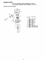
.JAaR PARTS
TILLER ATTACHMENT--MODEL
NUMBER
917.252492
8 H°P. ENGINE TECUMSEH--NiODEL
NUMBER
143_776012
CARBURETOR
NOd 632325
KEY
NO
1
2
3
14
/
PART
NO
DESCRIPTION
632325
631776
631970
631778
Carburetor
Shaft 8- Lever Assy. Throttle
Spring. Throttle return
Shutter, Throttle
Screw, Throttie Ef Choke shutter
Spring. Idle regulating screw
Spring, Main adjustment
screw
Screw, ldle regulating
Shaft [t Lever Assy, Choke
Spring, Choke posit{oning
Shutter. Choke
Plug, Welch
Plug, Weich
Inter Needle,
Seat 8- Clip Assy
{Incl No t3)
Clip, Inlet needIe
Float, Carburetor
Shaft, Float
BowI, Roar
Washer, Flat
Washer, Felt
Gasket, Bowl-to-body
Adjustment
Screw
Assy,
Main
(Incl_ Nos 5A, 21, 23 8- 30)
"0" Ring. Adjustment
screw
Screw, Idle adjustment
Gasket, Bowl-to-body
FueI fitting
Spring, Choke return
Seal, Dust
Washer, F_at
Repair Kit (Inct items marked *)
#J
/
15
6
\
-
23 . _
30
_
"
5A
_/
16
5
5A
46
7
8
9
630766
630738
650506
650417
632217
630735
631753
11
t2
10
13
14
15
t6
17
*631027
"631021
"630748
631022
632019
*631024
631867
631184
21
22
18
27110
*632239
631 t83
23
*630740
25
24
26
28
29
30
3t
%31028
*632281
632164
632043
631971
630739
632347
I09995X-10.21o86
-"19 -
Printed
in US,A,
8H.P.
30" SLEEVE HITCH
OWNERS
MANUAL
TILLER
ATTACHMENT
MODEL NO.
91 7.252492
The Model Number
will be found on a plate attached
to
the Transmission,
Always
provide
the Model Number
when requesting
service
or repair parts for your Tiller
Attachment°
All parts listed herein may
Service
Center!Departments
Stores.
be ordered
from any
and most
Sears
WHEN ORDERING
REPAIR PARTS,
FOLLOWING
INFORMATION:
HOW TO ORDER
REPAIR PARTS
@
O
O
O
Your
sider
THE
THE
THE
"THE
ALWAYS
Sears
Retail
GIVE THE
PART NUMBER
PART DESCRIPTION
MODEL NUMBER
NAME OF MERCHANDISE
Sears merchandise
Sears has service
has added value
units nationwide
when you constaffed
with
Sears trained technicians
having the parts, tools
equipment
to insure that we meet our pledge
"We Service
What We Sell'.
Sears, Roebuck and Co. Chicago, IL 60684 U.S.A.
and the
to you,