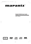
1
Model PM-11S1 User Guide Integrated Amplifier ENGLISH ITALIANO WARRANTY For warranty information, contact your local Marantz distributor. RETAIN YOUR PURCHASE RECEIPT Your purchase receipt is your permanent record of a valuable purchase. It should be kept in a safe place to be referred to as necessary for insurance purposes or when corresponding with Marantz. IMPORTANT When seeking warranty service, it is the responsibility of the consumer to establish proof and date of purchase. Your purchase receipt or invoice is adequate for such proof. FOR U.K. ONLY This undertaking is in addition to a consumer's statutory rights and does not affect those rights in any way. FRANÇAIS GARANZIA L’apparecchio è coperto da una garanzia di buon funzionamento della durata di un anno, o del periodo previsto dalla legge, a partire dalla data di acquisto comprovata da un documento attestante il nominativo del Rivenditore e la data di vendita. La garanzia sarà prestata con la sostituzione o la riparazione gratuita delle parti difettose. Non sono coperti da garanzia difetti derivanti da uso improprio, errata installazione, manutenzione effettuata da personale non autorizzato o, comunque, da circostanze che non possano riferirsi a difetti di funzionamento dell’apparecchio. Sono inoltre esclusi dalla garanzia gli interventi inerenti l’installazione e l’allacciamento agli impianti di alimentazione. Gli apparecchi verranno riparati presso i nostri Centri di Assistenza Autorizzati. Le spese ed i rischi di trasporto sono a carico del cliente. La casa costruttrice declina ogni responsabilità per danni diretti o indiretti provocati dalla inosservanza delle prescrizioni di installazione, uso e manutenzione dettagliate nel presente manuale o per guasti dovuti ad uso continuato a fini professionali. PORTUGUÊS GARANTIE Pour des informations sur la garantie, contacter le distributeur local Marantz. CONSERVER L'ATTESTATION D'ACHAT L'attestation d'achat est la preuve permanente d'un achat de valeur. La conserver en lieu sur pour s'y reporter aux fins d'obtention d'une couverture d'assurance ou dans le cadre de correspondances avec Marantz. IMPORTANT Pour l'obtention d'un service couvert par la garantie, il incombe au client d'établir la preuve de l'achat et d'en corroborer la date. Le reçu ou la facture constituent des preuves suffisantes. DEUTSCH GARANTIA Para informações sobre a garantia, contactar o distribuidor Marantz local. GUARDAR O RECIBO DE COMPRA O recibo é o registo permanente da compra que fez. Deve ser guardado num local seguro, para ser apresentado em questões relacionadas com o seguro ou para quando tiver de contactar a Marantz. IMPORTANTE Quando procurar assisténcia técnica ao abrigo da garantia, é da responsabilidade do consumidor estabelecer a prova e data de compra. O recibe é prova adequada. SVENSKA GARANTIE Bei Garantiefragen wenden Sie sich bitte an Ihren Marantz-Händler. GARANTI För information om garantin, kontakta Marantz lokalagent. HEBEN SIE IHRE QUITTING GUT AUF Die Quittung dient Ihnen als bleibende Unterlage für Ihren wertvollen Einkauf Das Aufbewahren der Quittung ist wichtig, da die darin enthaltenen Angaben für Versicherungswecke oder bei Korrespondenz mit Marantz angeführt werden müssen. SPAR KVITTOT Kvittot är ett inköpsbevis på en värdefull vara. Det skall förvaras säkert och hänvisas till vid försäkringsfall eller vidkorrespondens mod Marantz. WICHTIG! Bei Garantiefragen muß der Kunde eine Kaufunterlage mit Kaufdatum vorlegen. Ihren Quittung oder Rechnung ist als Unterlage ausreichend. VIKTIGT Fö att garantin skall gälla är det kundens sak att framställa bevis och datum om köpet. Kvitto eller faktura är tillräokligt bevis fö detta. DANSK NEDERLANDS GARANTIE Voor inlichtingen omtrent garantie dient u zich tot uw plaatselijke Marantz. UW KWITANTIE, KASSABON E.D. BEWAREN Uw kwitantie, kassabon e.d. vormen uw bewijs van aankoop van een waardevol artikel en dienen op een veilige plaats bewaard te worden voor evt, verwijzing bijv, in verbend met verzekering of bij correspondentie met Marantz. BELANGRIJK Bij een evt, beroep op de garantie is het de verantwoordelijkheid van de consument een gedateerd bewijs van aankoop te tonen. Uw kassabon of factuurzijn voldoende bewijs. GARANTI Henvend dem til Deres MARANTZ-forhandler angående inrformation om garantien. GEM DERES KVITTERING Deres købskvittering er Deres varige bevis på et dyrt køb. Den bør gemmes godt og anvendes som bevis, hvis De vil tegne en forsikring, eller hvis De kommunikerer med Marantz. VIGTIGT Det påhviler forbrugeren at skaffe bevis for købet og købsdatoen, hvis han eller hun ønsker garantiservice. Deres købskvittering eller faktura er et fuldgyldigt bevis herpå. ESPAÑOL GARANTIA Para obtener información acerca de la garantia póngase en contacto con su distribuidor Marantz. GUARDE SU RECIBO DE COMPRA Su recibo de compra es su prueba permanente de haber adquirido un aparato de valor, Este recibo deberá guardarlo en un lugar seguro y utilizarlo como referencia cuando tenga que hacer uso del seguro o se ponga en contacto con Marantz. IMPORTANTE Cuando solicite el servicio otorgado por la garantia el usuario tiene la responsabilidad de demonstrar cuándo efectuó la compra. En este caso, su recibo de compra será la prueba apropiada. PM-11S1N(Cover) Page 1 04.8.18, 1:49 AM Adobe PageMaker 6.5J/PPC CE MARKING English The PM-11S1 is in conformity with the EMC directive and low-voltage directive. Français Le PM-11S1 est conforme à la directive EMC et à la directive sur les basses tensions. Deutsch Das Modell PM-11S1 entspricht den EMC-Richtlinien und den Richtlinien für Niederspannungsgeräte. Nederlands De PM-11S1 voldoet aan de EMC eisen en de vereisten voor laag-voltage. Español El PM-11S1 está de acuerdo con las normas EMC y las relacionadas con baja tensión. Italiano Il PM-11S1 è conforme alle direttive CEE ed a quelle per i bassi voltaggi. Português O PM-11S1 conforma com as diretrizes EMC e de baixa voltagem. Svenska PM-11S1 är tillverkad i enlighet med EMC direktiven och direktiven för lågvoltsutrusning. Dansk Model PM-11S1 er i overensstemmelse med EMC-direktiveet og direktivet om lavspænding. English - - Deutsch WARNINGS Do not expose the equipment to rain or moisture. Do not remove the cover from the equipment. Do not insert anything into the equipment through the ventilation holes. Do not handle the mains lead with wet hands. Do not cover the ventilation with any items such as tablecloths, newspapers, curtains, etc. No naked flame sources, such as lighted candles, should be placed on the equipment. When disposing of used batteries, please comply with governmental regulations or environmental public instruction’s rules that apply in your country or area. Do not place anything about 0.2 meter above the top panel. Make a space of about 0.1 meter around the unit. Français - - - WARNHINWEISE Das Gerät nicht Regen oder Feuchtigkeit aussetzen. Die Abdeckung nicht vom Gerät abnehmen. Keine Gegenstände durch die Belüftungsschlitze stecken. Das Netzkabel nicht mit feuchten oder nassen Händen anfassen. Decken Sie die Lüftungsöffnungen nicht mit einem Tischtuch, einer Zeitung, einem Vorhang usw. ab. Es dürfen keine Gegenstände mit offener Flamme, wie etwa brennende Kerzen, auf dem Gerät aufgestellt werden. Beachten Sie bei der Entsorgung der verbrauchten Batterien alle geltenden lokalen und überregionalen Regelungen. Darauf achten, daß über dem Gerät ein Freiraum von mindestens 0,2 meter vorhanden ist. Auf allen Geräteseiten muß ein Zwischenraum von ungefähr 0,1 meter vorhanden sein. Nederlands AVERTISSEMENTS Ne pas exposer l’appareil à la pluie ni à l’humidité. Ne pas essayer de retirer le boîtier de l’appareil. Ne rien insérer dans l’appareil par les orifices de ventilation. Ne pas manipuler le cordon d’alimentation avec les mains mouillées. Ne pas recouvrir les ouïes de ventilation avec un objet quelconque comme une nappe, un journal, un rideau, etc. Ne placer aucune source de flamme nue, comme une bougie allumée, sur l'appareil. Pour mettre au rebut les piles usées, respecter les lois gouvernementales ou les règlements officiels concernant l’environnement qui s'appliquent à votre pays ou région. Ne placez aucun object à moins de 0,2 mètre environ du panneau supérieur. Veiller à ce qu’aucun objet ne soit à moins de 0,1 mètre des côtés de l'appareil. PM-11S1N(Cover) - Page 2 - - WAARSCHUWINGEN Stel het apparaat niet bloot aan regen of vocht. Verwijder de afdekplaat van het apparaat niet. Duw niets door de ventilatieopeningen in het apparaat. Raak het netsnoer niet met natte handen aan. Bedek de ventilatieopeningen niet met enige voorwerpen, zoals tafelkleden, kranten, gordijnen, enz. Plaats geen brandende voorwerpen, zoals kaarsen, op het apparaat. Volg bij het weggooien van verbruikte batterijen de overheidswetgeving of milieuvoorschriften op die van kracht zijn in het land of de regio waarin u zich bevindt. Zorg dat er tenminste 0,2 meter vrije ruimte boven het toestel is. Zorg dat er 0,1 meter vrije ruimte rond het toestel is. 04.8.18, 1:49 AM Adobe PageMaker 6.5J/PPC Español Svenska ADVERTENCIAS - No exponga el equipo a la lluvia ni a la humedad. - No extraiga la tapa del equipo. - No introduzca nada en el interior del equipo a través de los orificios de ventilación. - No maneje el cable de alimentación con las manos mojadas. - No cubra la ventilación con objetos como manteles, periódicos, cortinas, etc. - No deben colocarse sobre el equipo elementos con fuego, por ejemplo velas encendidas. - Cuando se eliminen baterías usadas, deben cumplirse las reglamentaciones oficiales o las normas de protección medioambiental aplicables en su país o en su zona. - No ponga nada a menos de 0,2 metro por encima del panel superior. - Deje un espacio de unos 0,1 metro alrededor de la unidad. - VARNINGAR Utsätt inte utrustningen för regn eller fukt. Ta inte bort utrustningens hölje. För inte in föremål i utrustningen genom ventilationshålen. Hantera inte nätsladden med våta händer. Täck inte för ventilationsöppningarna med några föremål som till exempel bordsdukar, dagstidningar, gardiner e.d. Inga föremål med öppen låga, som till exempel tända stearinljus, bör placeras på utrustningen. Följ de lagar och miljöskyddsråd som gäller i det land eller område där du bor när du gör dig av med batterier. Placera inte någonting närmare än 0,2 meter ovanför apparaten eller enheten. Se till att det finns omkring 0,1 meter fri plats runt omkring enheten. Dansk Italiano - AVVERTENZE Non esporre l’apparecchio alla pioggia o all’umidità. Non rimuovere il coperchio dell’apparecchio. Non introdurre oggetti all’interno dell’apparecchio attraverso i fori di ventilazione. Non toccare il cavo di alimentazione con le mani bagnate. Non coprire le fessure di ventilazione con tovaglie, giornali, tende od oggetti analoghi. Non posare sull'apparecchio sorgenti di fiamme scoperte quali candele accese. Smaltire le pile usate in conformità alle norme governative o disposizioni ambientali vigenti nel proprio paese o zona. Non posare alcun oggetto sopra il pannello superiore, lasciando libero uno spazio di circa 0,2 m. Lasciare 0,1 metro liberi tutto intorno l'unità. - - ADVARSLER Udsæt ikke udstyret for regn eller fugt. Fjern ikke dækslet fra udstyret. Stik ikke noget ind i udstyret gennem ventilationshullerne. Rør ikke ved netledningen med våde hænder. Tildæk ikke ventilationsåbningerne med ting som duge, aviser, gardiner og lignende. Kilder til åben ild, som for eksempel tændte sterarinlys, må ikke anbringes på apparatet. Når du skiller dig af med gamle batterier, bedes du gøre dette i overensstemmelse med de love, regler og miljømæssige forskrifter, som er gældende i dit land eller område. Anbring ikke noget nærmere end 0,2 m over apparatets overside, Sørg for, at der er et frit område på omkring 0,1 m omkring apparatet. Português ADVERTÊNCIAS - Não exponha o equipamento à chuva nem à humidade. - Não retire a tampa do equipamento. - Não atire nada para dentro do equipamento através dos orificíos de ventilação. - Não manuseie o cabo de alimentação com as mãos molhadas. - Não cobrir os orifícios de ventilação com objectos tais como toalhas de mesa, jornais, cortinas, etc. - Não colocar chamas abertas tais como velas acesas, sobre o aparelho. - Ao deitar foras as pilhas usadas, favor observar os regulamentos governamentais ou as regras com respeito ao meio ambiente que se aplicam no seu país ou área de residência. - Deixar um espaço completamente livre de cerca de 0,2 metro acima do painel superior. - Deixar um espaço de cerca de 0,1 metro ao redor do aparelho. PM-11S1N(Cover) Page 3 04.8.18, 1:49 AM Adobe PageMaker 6.5J/PPC 2 3 4 5 ABOUT THE BALANCED INPUT JACKS ........................................................................................................... 5 WIRING SPEAKER CABLE ................................................................................................................................ 5 BI-WIRING CONNECTION ................................................................................................................................. 6 COMPLETE BI-AMP CONNECTION .................................................................................................................. 6 SPEAKER POSITIONING FOR SUPER AUDIO MULTI-CHANNEL SOUND .................................................... 6 CONNECTIONS .................................................................................................................................... 7 NAMES AND FUNCTIONS OF PARTS ............................................................................................... 10 FRONT PANEL ................................................................................................................................................. 10 DISPLAY ........................................................................................................................................................... 11 REAR PANEL ................................................................................................................................................... 12 RC-11PMS1 REMOTE CONTROLLER ............................................................................................................ 13 BASIC OPERATION ............................................................................................................................ 15 PLAYBACK ........................................................................................................................................................ 15 RECORDING .................................................................................................................................................... 16 HOW TO USE AND SET FEATURES .................................................................................................. 17 ABOUT FCBS ................................................................................................................................................... 17 ABOUT THE BI-AMP MODE ............................................................................................................................ 17 ATTENUATION (ATT) ........................................................................................................................................ 18 HOW TO OPERATE THE SIDE ILLUMINATION ............................................................................................... 18 TRIMMING ........................................................................................................................................................ 19 HOW TO ADJUST DISPLAY CONTRAST ........................................................................................................ 21 HOW TO SET ID ............................................................................................................................................... 21 TROUBLESHOOTING ......................................................................................................................... 22 OTHERS .............................................................................................................................................. 23 SPECIFICATIONS & DIMENSIONAL DRAWINGS .............................................................................. 24 1 PM-11S1N ENG(P01-P06)A4 Page 1 04.8.17, 11:34 PM Adobe PageMaker 6.5J/PPC ENGLISH FOREWORD .......................................................................................................................................... FEATURES ............................................................................................................................................ BEFORE USE ........................................................................................................................................ BEFORE MAKING CONNECTIONS ..................................................................................................... ENGLISH CONTENTS ENGLISH ENGLISH FOREWORD This section must be read before any connection is made to the mains supply. 7 EQUIPMENT MAINS WORKING SETTING Your Marantz product has been prepared to comply with the household power and safety requirements that exist in your area. PM-11S1 can be powered by 230V AC only. 7 COPYRIGHT Recording and playback of any material may require consent. For further information refer to the following: — Copyright Act 1956 — Dramatic and Musical Performers Act 1958 — Performers Protection Acts 1963 and 1972 — Any subsequent statutory enactments and orders 2 PM-11S1N ENG(P01-P06)A4 Page 2 04.8.17, 11:34 PM Adobe PageMaker 6.5J/PPC INTEGRARED AMPLIFIER PM-11S1 DISPLAY ATT. TONE PRE OUT OPERATE SPEAKER A REC OUT INPUT SELECTOR VOLUME POWER ON/OFF SPEAKER B PHONES The PM-11S1 is an integrated amplifier developed on the concepts of Marantz’s SC-7S1 and MA-9S1 flagship amplifiers. • HDAM SA2 The HDAMSA2 is an evolved version of the HDAMSA incorporated into the SC-7S1 and MA-9S1. It drives the phono amplifier, balance buffer, line buffer, volume amplifier, voltage amplifier and power buffer that comprise the PM-11S1. Input Amplifier • Current Feedback Phono Equalizer The phono equalizer of the PM-11S1 supports MC/MM cartridges and incorporates the first-ever current feedback circuit used with a Marantz product. The newly designed circuitry employs both Marantz’s previous HDAM and the newly developed HDAMSA2. • Current Feedback Balance Buffer The PM-11S1 incorporates an HDAMSA2-driven current feedback balance buffer that faithfully transfers signals from devices of quality balanced output such as super audio CD players and D/A converters. • Individual Input Buffer for Each Line Input Jack Each the CD, LINE 1, LINE 2, RECORDER 1 and RECORDER 2 input jack has its own input buffer built on HDAMSA2 technology. By providing each line with its own buffer amp, it is possible to prevent interference between input sources and thereby faithfully transfer signals from the input source. Preamplifier • Linear Control Volume The PM-11S1 incorporates linear control volume that carry forward the design concepts of the SC-7S1. In combination with the WM8816 by Wolfson and the HDAMSA2, these linear control varistors improve S/N ratio, enabling smooth control in ±0.5 dB steps across a 0 - -100 dB range. PHONO MC Power Amplifier • Dual Amplifier Structure The PM-11S1 carries on the dual amplifier design concepts of the MA-9S1 with separate voltage and power amplifiers. With this dual amp structure, the power buffer powerfully drives the speakers whereby shutting out the effects of return current from the speakers. The voltage amplifier drives the power buffer with ultra low distortion. Power • Choke Input Power Supply The PM-11S1 incorporates a choke input power circuit built with a high capacity smoothing capacitor in order to thoroughly eliminate high frequency noise from the rectifier circuit and external sources. It delivers a distortion-free power supply to the input amplifier and preamplifier. Functions • Bi-Amp Mode The complete bi-amp connection proposed by Marantz with the SC-7S1 and MA-9S1 reproduces a sound environment never before experienced. This same bi-amp connection has been made possible with the PM-11S1. Two PM-11S1s are connected by FCBS in a bi-amp mode that enables each to work as a monaural integrated amplifier. • Floating Control Bus System A Floating Control Bus System (FCBS) enables the user to connect up to four PM-11S1s, making possible a diversity of applications with complete bi-amp and multiple channel connections. Moreover, a ground loop is not formed between multiple connected PM-11S1s, therefore sound quality is not adversely affected. • Display The PM-11S1 adopts an LCD to display input source and volume level. Compared to other types of display panels, an LCD generates less drive noise and radiated noise, hence the effect on sound quality is minimal. • Tone Control Amplifier The PM-11S1 incorporates an adjustable jack-type tone control amplifier for controlling bass and treble in 2 dB steps across a ±8 dB range. The left and right channels can be separately adjusted from the remote controller. 3 PM-11S1N ENG(P01-P06)A4 Page 3 04.8.17, 11:34 PM Adobe PageMaker 6.5J/PPC ENGLISH ENGLISH FEATURES ENGLISH ENGLISH BEFORE USE 7 Do Not Locate in the Following Places To ensure long-lasting use, do not locate the PM-11S1 where: • Exposed to direct sunlight. • Near to sources of heat such as heaters. • Highly humid or poorly ventilated. • Dusty. • Subjected to mechanical vibrations. • On wobbly, inclined or otherwise unstable surfaces • Radiated heat is blocked such as in cramped audio racks. To ensure proper heat radiation, ensure the below clearance from walls and other equipment. Above 20 cm or more Right 10 cm or more Left 10 cm or more ATT. TONE Improper use of dry cell batteries can result in electrolyte leaks, rupture and corrosion. Read the following precautions before use. • If not planning to use the remote controller for an extended period of 1 month or more, remove the batteries. • Do not mix old batteries with new batteries. • Load batteries in the proper direction indicated on the remote controller. • Do not mix batteries of differing type. Even batteries of the same shape and size can have differing voltages. • If batteries leak, wipe the case clean of any adhering electrolyte and replace the old batteries with new batteries. 7 Accessories Check Before use, check the below accessories were included in the package. • AC power cable INTEGRARED AMPLIFIER PM-11S1 DISPLAY 7 Battery Handling PRE OUT OPERATE SPEAKER A REC OUT INPUT SELECTOR VOLUME POWER ON/OFF SPEAKER B PHONES PHONO MC Rear 10 cm or more The power cable included in the package can be used with the PM-11S1 only. It cannot be used with other equipment. • RC-11PMS1 remote controller • AAA batteries x 2 OPEN/ CLOSE SOUND MODE PHONO BALANCED CD RECORDER 1 LINE 1 RECORDER 2 LINE 2 TRIM EXIT TONE + L R ENTER - DISPLAY 7 Keep Objects Off ATT VOLUME Keep objects off the PM-11S1. Blocking the vent can result in accident and damage. 7 Do Not Touch Hot Spots During and Immediately After Use During and immediately after use, the PM-11S1 is hot in areas other than the controls and rear panel connection jacks. Do not touch hot spots and especially the top panel. Contact with hot areas can cause burns. RANDOM SCAN REPEAT TOP MENU RETURN MENU AM/A FM/B RC-11PMS1 • Instruction Manual (This manual) 4 PM-11S1N ENG(P01-P06)A4 Page 4 04.8.17, 11:34 PM Adobe PageMaker 6.5J/PPC q The PM-11S1 uses XLR connectors for the BALANCED INPUT jacks. XLR connectors are widely used with professional equipment because of the following features. • Incoming music signals are balanced, therefore they are little affected by external noise. • The detachable locking mechanism minimizes connector play and enhances connection reliability. WIRING SPEAKER CABLE • Be careful not to short circuit in wiring speaker cables. • Peel off the corting of speaker cable as shown below. Approx. 1 cm Cut the corting of cable. Peel off the edge of cable. Twist conductors. w There are two ways to connect the XLR connectors. 1.In the USA • Wiring with speaker cable. COLD 2 1 GND 3 HOT 2.In Europe HOT 2 1 GND Turn counter-clockwise to loosen. Insert conductor of cable. Turn clockwise to tighten. 3 COLD • Wiring with “Y” style terminal e The PM-11S1 adopts the USA circuitry. If the PM-11S1 is connected via a balanced cable to a preamplifier or control amplifier of European circuitry, signal phases will be reversed. To correctly align signal phases, switch the w and e pins of one of the XLR connectors. Turn counter-clockwise to loosen. Insert conductor. Turn clockwise to tighten. Your speaker system must satisfy the below conditions. If it does not, the PM-11S1’s protective circuit will trip, whereby preventing proper playback. In some cases, the amplifier and speakers may be damaged. • If using 1 set of speakers, total speaker impedance must be 4Ω or more. • If using 2 sets of speakers, total speaker impedance must be 8Ω or more. 5 PM-11S1N ENG(P01-P06)A4 Page 5 04.8.17, 11:34 PM Adobe PageMaker 6.5J/PPC ENGLISH ABOUT THE BALANCED INPUT JACKS ENGLISH BEFORE MAKING CONNECTIONS ENGLISH ENGLISH BEFORE MAKING CONNECTIONS Here following are explained two types of connections that improve sound quality. The speakers in these explanations have low and mid/high input jacks that support a bi-amp connection. To determine whether or not your speakers support a biamp connection, check in the instruction manual that came with your speakers or contact the manufacturer. BI-WIRING CONNECTION A bi-wiring connection separately connects the low and mid/ high jacks of the speaker to the amplifier using separate speaker cables. Because separate cables are used for low and mid/high sounds, the return current generated in the low speaker causes little interference with the mid/high speaker. The PM-11S1 and speakers of Connection Example 1 use a bi-wiring connection, therefore also refer to that page for help. CD player, etc. PM-11S1 Bi-wiring Speaker system connection Mid/high speaker Band pass filter Low speaker COMPLETE BI-AMP CONNECTION Proposed by Marantz, the complete bi-amp connection enhances the bi-wiring connection. With it, the low and mid/high amplifiers are separate and independent of the preamplifier, therefore interference between low and mid/high sounds is reduced to a minimum. As a result, a wide sound environment can be reproduced. Connection Example 3 connects two PM11S1s by FCBS in a complete bi-amp connection, therefore also refer to that page for help. Complete bi-amp connection Speaker system CD player, etc. SPEAKER POSITIONING FOR SUPER AUDIO MULTI-CHANNEL SOUND In order to enjoy Super Audio CD multi-channel sound with the best possible acoustics, it is recommended to position speakers as specified in ITU-R BS.775-1 of the International Telecommunication Union (ITU). Super Audio CD multi-channel discs are recorded and mixed so as to achieve the optimum effect with a speaker system laid out as specified in ITUR BS.775-1. • With Super Audio CD multi-channel discs, the music signals are basically recorded using 5 channels (3 - 6 channels sometimes), but in some cases, LFE (for subwoofer) is recorded as a sixth channel. Each disc indicates how many channels have been recorded on it. • The basic layout is 3 speakers in the front and 2 in the back since multi-channel discs usually have 5 channels. The 2 front, 1 center and 2 surround (rear) speakers should be set in a circle around the listening point as shown below. If using speakers of differing sizes, adjust volume balance from the amplifier. • The location of the subwoofer in the figure is just for explanatory purposes. It can be located anywhere in the room. For connection and positioning instructions, see the instruction manual that came with the subwoofer. 7 ITU (International Telecommunication Union) The ITU is a special organization of the United Nations. It consists of a number of organs, one of which is the Radio Broadcasting Section. ITU-R BS in the recommendation which consists of standards relating to broadcasting (audio) operations, one of which is the ITU-R BS.775-1 which governs “multi-channel stereo sound systems.” Center speaker Sub-woofer Front speaker (Left) Front speaker (Right) Mid/high speaker PM-11S1 biamp mode Band pass filter Low speaker approx. 110° approx. 110° Reference listening position Rear speaker (Left Surround) Rear speaker (Right Surround) 6 PM-11S1N ENG(P01-P06)A4 Page 6 04.8.17, 11:34 PM Adobe PageMaker 6.5J/PPC CONNECTIONS Connection Example 1: Basic Connection for Normal Stereo Playback Refer also to the instruction manuals of components to connect equipment correctly. • Use a bi-wiring connection for speakers. Set the SPEAKER A and B buttons on the front panel in the ON position. • If using speakers that do not support a bi-wiring connection, connect them to either the SPEAKER SYSTEM A or B terminals. • If using an active subwoofer, set the PRE OUT button on the front panel in the ON position. • To record, set the REC OUT button on the front panel in the ON position. CD player Record player To balanced output jacks SUPER AUDIO CD PLAYER SA-11S1 OPEN/ CLOSE PLAY STOP DISPLAY OFF SOUND MODE POWER ON/OFF PAUSE Set to “STEREO”. CD player To LINE OUT jacks SUPER AUDIO CD PLAYER SA-11S1 OPEN/ CLOSE PLAY STOP DISPLAY OFF SOUND MODE POWER ON/OFF PAUSE 3 2 DVD player, etc. DVD PLAYER DV-12S1 VIDEO ON/OFF DIMMER AC IN 3 1 2 1 To LINE OUT jacks Tuner, etc. OPEN/CLOSE PLAY To LINE OUT jacks STOP PAUSE RANDOM V-PART DVD AUDIO GRP TITLE POWER STANDBY 192kHz 96kHz TRK DIG OFF CHP LAST MEMO CONDITION DOWN MIX PROGRESSIVE DOLBY D TEMAIN TOTAL VIDEO OFF L LS C R LFE S RS FL OFF To power outlet To LINE OUT jacks CD-R, etc. To LINE IN jacks To LINE OUT jacks Tape deck, etc. To LINE IN jacks MF / HF MF / HF LF LF To LINE IN jacks Active subwoofer, etc. Remove shorting bar. L CH speaker Remove shorting bar. Remove shorting bar. R CH speaker Remove shorting bar. 7 CONNECTIONS Connection Example 2: Basic Connection for 5.1 Multi-Channel Playback Using 3 PM-11S1 The three PM-11S1s are connected by FCBS. For the FCBS connection, prepare 3 portable audio connection cables with monaural ⇔ monaural miniplugs or stereo ⇔ stereo miniplugs as described “ABOUT FCBS” on pg. 17. Set the ID numbers for the PM-11S1 units as explained “HOW TO SET ID” on pg. 21. When the PM-11S1 of ID 1 is operated, those of ID 2 and ID 3 will operate in sync. If using an active subwoofer, see the instruction manual that came with the subwoofer for connection and positioning instructions. SACD multi-channel player, etc. MULTI CHANNEL AUDIO OUT FRONT R For front L/R speakers Set PM-11S1 to ID 1. Set SPEAKER A button on front panel in ON position. 3 2 Set to “STEREO”. 2 1 SURROUND R SURROUND L SUB-WOOFER For center speaker or subwoofer Set PM-11S1 to ID 2. Set SPEAKER A button on front Set to “STEREO”. panel in ON position. Set PRE OUT button on front panel in ON position. AC IN 3 1 FRONT L 3 2 2 For surround speakers Set PM-11S1 to ID 3. Set SPEAKER A button on front panel in ON position. AC IN 3 1 CENTER 1 To power outlet 3 2 Set to “STEREO”. AC IN 3 1 2 1 To power outlet To power outlet To line input jack L CH front speaker 8 R CH front speaker Active subwoofer Front center speaker L CH surround speaker R CH surround speaker SUPER AUDIO CD PLAYER SA-11S1 OPEN/ CLOSE PLAY STOP DISPLAY OFF POWER ON/OFF SOUND MODE Set SPEAKER A button on front panel in ON position. PAUSE Set to “BI-AMP”. Set PM-11S1 for L CH to ID 1. 3 2 AC IN 3 1 2 Set SPEAKER A button on front panel in ON position. 1 Set to “BI-AMP”. Set PM-11S1 for R CH to ID 2. 3 2 AC IN 3 1 2 1 To power outlet To power outlet MF / HF MF / HF LF LF Remove L CH speaker shorting bar. Remove shorting bar. Remove R CH speaker shorting bar. Remove shorting bar. 9 PM-11S1N ENG(P09-P26)A4 Page 9 04.8.17, 11:36 PM Adobe PageMaker 6.5J/PPC ENGLISH Connection Example 3: Complete Bi-Amp Connection for Stereo Playback Using 2 PM-11S1 The speaker system must support a bi-amp connection, therefore to determine whether your speakers do or not, check in the instruction manual that came with your speakers or contact the manufacturer. The two PM-11S1s are connected by FCBS. For the FCBS connection, prepare 2 portable audio connection cables with monaural ⇔ monaural miniplugs or stereo ⇔ stereo miniplugs as described “ABOUT FCBS” on pg. 17. Set the ID numbers for the PM-11S1 units as explained “HOW TO SET ID” on pg. 21. When the PM-11S1 of ID 1 is operated, that of ID 2 will operate in sync. ENGLISH CONNECTIONS ENGLISH ENGLISH NAMES AND FUNCTIONS OF PARTS FRONT PANEL INTEGRARED AMPLIFIER PM-11S1 DISPLAY ATT. TONE PRE OUT OPERATE SPEAKER A REC OUT INPUT SELECTOR VOLUME POWER ON/OFF SPEAKER B PHONES q POWER ON/OFF Switch This switch turns power to the PM-11S1 ON and OFF. When pressed, power is activated and the blue indicator on the display w lights up. Approximately 8 seconds after power is activated, audio output is enabled. Pressing the switch again turns power OFF. w Display The display displays the selected input source, volume level and setting status. e INPUT SELECTOR Knob This knob is for selecting the input source to use in playback and recording. The selected input source is displayed on the display w. r VOLUME Knob This knob is for setting the volume. The volume level is displayed on the display w. Turning the knob clockwise increases the volume, while turning it counterclockwise decreases the volume. When turned slowly, the volume can be fine-adjusted in 0.5 dB steps, whereas when turned rapidly, volume level changes greatly. t Infrared Receptor Window This is the receptor of control signals sent from the included RC-11PMS1 remote controller. Point the remote controller towards this window to properly send signals. y PHONES Jack This jack is for connecting headphones with a standard stereo plug. To listen with headphones, turn speaker output OFF by setting the SPEAKER A and B buttons in the OFF position. u DISPLAY Button This button turns the display and side illumination ON and OFF. The button performs two functions depending on how long it is pressed. If pressed and held for 3 seconds or longer: PHONO MC Turns the side illumination !4 on both sides of the display ON and OFF. This operation sets the always-ON mode of the side illumination, therefore once the side illumination is turned OFF, it stays OFF and does not light even if power is shut OFF and reactivated. To turn the side illumination ON again, press and hold the DISPLAY button for 3 seconds or longer. If pressed and held for less than 3 seconds: Turns the display ON and OFF. When the always-ON mode is engaged for the side illumination, the side illumination turns ON and OFF in synch with the display. If the display is out and the VOLUME knob or other control is operated, the display lights up. It will automatically go out 3 seconds after the operation has been completed. For instructions on how to operate the side illumination, see “HOW TO OPERATE THE SIDE ILLUMINATION” on pg. 18. i TONE Button This button turns the bass and treble tone control ON and OFF. When tone control is ON, the center of the button is lit a blue color. For instructions on how to adjust bass and treble, see “How to Trim Bass” and “How to Trim Treble” on pg. 20. o SPEAKER A/B Buttons These buttons turn the speaker output to the speakers connected to the SPEAKER SYSTEM A/B terminals on the rear panel ON and OFF. When speaker output is ON, the center of the button is lit a blue color. To listen with headphones, turn speaker output OFF. !0 ATT Button This button attenuates volume with one press of the button. When pressed, “ATT” flashes on the display and the volume is reduced. If pressed again, the mode is canceled and the original volume level is restored. Attenuation level is set to –20 dB when the PM-11S1 is shipped from the factory, but it can be set to either –40 dB or -∞ (mute). For instructions on how to set attenuation level, see “How to Set Attenuation Level” on pg. 18. 10 PM-11S1N ENG(P09-P26)A4 Page 10 04.8.17, 11:36 PM Adobe PageMaker 6.5J/PPC This button turns output from the PRE OUT jack on the rear panel ON and OFF. When output is ON, the center of the button is lit a blue color. !2 REC OUT Button This button turns the signals output from the RECORDER 1 and 2 OUT jacks on the rear panel ON and OFF. When output is ON, the center of the button is lit a blue color. For instructions on how to record, see “RECORDING” on pg. 16. When RECORDER 1 is selected as the input source, signals are not output to the RECORDER 1 OUT jack. The same goes for the RECORDER 2 OUT jack when RECORDER 2 is selected as the input source. !6 Display Panel Approximately 3 seconds after power to the PM-11S1 is activated, the ID set for the PM-11S1 is displayed here. After that, the top line displays the input source selected with either the INPUT SELECTOR knob or the remote controller, while the bottom line displays the volume level set with the VOLUME knob or the remote controller. When the PM-11S1 I is first activated, the attenuation level (dB) is displayed for the initial volume level. Volume Level Indication Max !3 PHONO MC Button Turn the VOLUME knob on the PM-11S1 to the right or press the VOLUME 3 button on the remote controller. This button switches the phono equalizer between MC and MM. When MC is set, the center of the button is lit a blue color. Set the phono equalizer amplifier according to the type of cartridge you use. !4 Side Illumination The side illumination casts a blue light over switches and buttons. It can be turned ON and OFF from the DISPLAY button. For instructions on how to operate the side illumination, see “HOW TO OPERATE THE SIDE ILLUMINATION” on pg. 18. 0.5 dB steps Turn the VOLUME knob on the PM-11S1 to the left or press the VOLUME 4 button on the remote controller. DISPLAY Min The display panel also displays left-right level balance and tone control trimming level. For instructions on how to adjust bass and treble, see “How to Trim Bass” and “How to Trim Treble” on pg. 20. The display panel also displays messages in response to PM-11S1 operation. OPERATE !7 OPERATE Indicator !5 Power Indicator This indicator is lit a blue color while power to the PM11S1 is ON. This indicator indicates the operating status of the PM11S1. When the ID is set to “0” for standalone operation, it is lit a red color. When multiple PM-11S1s are connected by FCBS, only the OPERATE indicator of the master PM11S1 (ID 1) lights a red color. Slave PM-11S1s whose OPERATE indicator does not light a red color cannot be used to operate other units in sync. For more information on the FCBS, see “ABOUT FCBS” on pg. 17. Also, the OPERATE indicator flashes if a protective circuit trips. For troubleshooting procedures, see “TROUBLESHOOTING” on pg. 22. 11 PM-11S1N ENG(P09-P26)A4 Page 11 04.8.17, 11:36 PM Adobe PageMaker 6.5J/PPC ENGLISH !1 PRE OUT Button ENGLISH NAMES AND FUNCTIONS OF PARTS ENGLISH ENGLISH NAMES AND FUNCTIONS OF PARTS REAR PANEL 3 2 AC IN 3 1 2 1 A PHONO GND Terminal Connect the grounding wire from an analog record player here. B PHONO Input Jacks These jacks are for connecting to an analog record player. Both MC and MM cartridges can be used, therefore set the PHONO MC button on the front panel according to the type of cartridge you are using. In the bi-amp mode, the R channel jack cannot be used. C BALANCED INPUT Jacks These jacks are for connecting to the balanced output jacks of a CD player or D/A converter. With the BALANCED INPUT jacks of the PM-11S1, pin 1 is GND, pin 2 is Cold and pin 3 is Hot. In the bi-amp mode, the R channel jack cannot be used. D CD Input Jacks These jacks are for connecting to the output jacks of a Super Audio CD player, CD player, etc. In the bi-amp mode, the R channel jack cannot be used. E LINE 1/2 Input Jacks These jacks are for connecting to the output jacks of a tuner, DVD player, etc. In the bi-amp mode, the R channel jack cannot be used. F RECORDER 1/2 IN Jacks These jacks are for connecting to the output jacks of a CDR, MD deck, tape deck, etc. In the bi-amp mode, the R channel jack cannot be used. G RECORDER 1/2 OUT Jacks These jacks are for connecting to the recording input jacks of a CD-R, MD deck, tape deck, etc. Output signals can be turned ON/OFF from the REC OUT button on the front panel. In the bi-amp mode, the signals input to the L channel are output to both output jacks. H PREOUT Jacks These jacks are for connecting to the input jacks of another main amplifier or active subwoofer. Output signals can be turned ON/OFF from the PRE OUT button on the front panel. In the bi-amp mode, the signals input to the L channel are output to both output jacks. I SPEAKER SYSTEMS Output Terminals You can connect 2 speaker systems to the PM-11S1. Speaker output can be turned ON/OFF from the SPEAKER A and B buttons on the front panel. In the bi-amp mode, the signals input to the L channel are output to both output terminals. J F.C.B.S. IN/OUT Jacks You can connect and synchronize up to four PM-11S1s in a complete bi-amp connection or multi-channel connection. A stereo miniplug or monaural miniplug cable can be used for the connections. For instructions on use and connections, see “ABOUT FCBS” on pg. 17. K Operating Mode Switch This switch is for setting the operating mode of the PM11S1. STEREO: Set to use the PM-11S1 as an ordinary 2-channel stereo amplifier. BI-AMP: Set to use two PM-11S1s in a complete bi-amp connection with FCBS. For more information on the bi-amp mode, see “ABOUT THE BI-AMP MODE” on pg. 17. L AC IN Socket Connect one end of the included power cable here and the other end to a power outlet. The PM-11S1 can be powered by 230V AC only. 12 PM-11S1N ENG(P09-P26)A4 Page 12 04.8.17, 11:36 PM Adobe PageMaker 6.5J/PPC This remote controller can control the PM-11S1 and Marantz Super Audio CD players and DVD players that have a remote control receptor. The operations possible by remote control may differ with each component, therefore see the instruction manual that came with the component. Remote controller buttons are laid out as shown below. z Input Selector Buttons These buttons are for selecting the input source to use in playback. x TRIM Button This button starts trimming. When multiple PM-11S1s are connected by FCBS, this button selects the amplifier with which to perform trimming. c EXIT Button OPEN/ CLOSE This button ends the trimming mode when trimming is finished. SOUND MODE v TONE Button PHONO BALANCED CD This button turns tone (bass /treble) control ON and OFF. RECORDER 1 LINE 1 RECORDER 2 TRIM b ATT Button LINE 2 EXIT TONE This button attenuates volume level with one press. + n Volume Buttons L R 3 : This button increases the volume level. 4 : This button decreases the volume level. ENTER - DISPLAY ATT m DISPLAY Button This button turns the display ON and OFF. VOLUME , Cursor Buttons RANDOM SCAN REPEAT TOP MENU RETURN MENU AM/A FM/B RC-11PMS1 In the Trimming Mode These buttons are for selecting the channel to trim and the trimming level. ENTER: This button selects the trim mode (LEVEL. BASS or TREBLE). 2 /R : This button selects the R channel for trimming. 1 /L : This button selects the L channel for trimming. 3 /+ : This button increases the trimming level. 4 /– : This button decreases the trimming level. Other Than the Trimming Mode 2, 1, 3, 4 and ENTER: These buttons are for selecting settings items on menu displays of Marantz DVD players, etc. For operations of supported Marantz products, see the tables on the following page and the instruction manual of the Marantz component. . Component Operating Buttons These buttons are for operating Marantz Super Audio CD players, DVD players, etc. For operations of supported Marantz products, see the tables on the following page and the instruction manual of the Marantz component. 13 PM-11S1N ENG(P09-P26)A4 Page 13 04.8.17, 11:36 PM Adobe PageMaker 6.5J/PPC ENGLISH RC-11PMS1 REMOTE CONTROLLER ENGLISH NAMES AND FUNCTIONS OF PARTS ENGLISH ENGLISH NAMES AND FUNCTIONS OF PARTS The buttons in groups , and . are for operating Marantz products other than the PM-11S1, such as Super Audio CD players and DVD players. The function of each button changes to match the component selected as the input source from the input selector buttons z. When the CD and BALANCED buttons are pressed, the buttons in groups , and . function as indicated in the below table. These buttons can be used only when a Marantz Super Audio CD player is connected to the CD input or BALANCED INPUT jacks. Button OPEN/CLOSE SOUND MODE 3 4 ¢ 1 ¡ 8 7 RANDAM SCAN REPEAT TOP MENU/AM/A RETURN/FM/B MENU 1 2 ENTER 3 /+ 4 /– 1/L 2/R Function Open/Closes disc tray. Selects Super Audio CD sound mode. Selects Super Audio CD/CD. Play Track skip (Returns to track beginning/previous track.) Track skip (Advances to next track.) Rewind search Forward search Pause Stop Random play AMS (Automatic Music Scan) play Repeat play Not available for use Not available for use Sets quick replay. Starts quick replay. Not available for use Not available for use Not available for use Not available for use 7 For use of Remote controller • Loading batteries Before using the supplied remote control unit for the first time, load the batteries in the remote control unit. The batteries provided are used to verify the operations of the remote control unit only. 1. Remove the battery cover which is found on the back side of the remote control unit. 2. Load the two new size “AAA” batteries inside the battery compartment while taking care to align their polarities correctly with the polarity markings ( with and with ). 3. Push the cover on the back side in the direction of the arrow to close. 7 Operatable range of Remote controller Operate the remote control unit (RC-11PMS1) within a distance of approx. 5 m from the infrared signal reception window (remote sensor) on the front of the PM-11S1. When the LINE 2 button is pressed, the buttons in groups , and . function as indicated in the below table. These buttons can be used only when a Marantz DVD player is connected to the LINE 2 input jacks. Button OPEN/CLOSE SOUND MODE 3 4 ¢ 1 ¡ 8 7 RANDAM SCAN REPEAT TOP MENU/AM/A RETURN/FM/B MENU 1 2 ENTER 3 /+ 4 /– 1/L 2/R Function Open/Closes disc tray. Changes sound mode. Play Track skip (Returns to track beginning/previous track.) Track skip (Advances to next track.) Rewind search Forward search Pause Stop Random play Selects search mode. Repeat play Displays top menu. Returns to previous menu Displays menu screen. Sets selected item. Moves cursor upward. Moves cursor downward. Moves cursor to left. Moves cursor to right. Approx. 5m 60° Remote control unit (RC-11PMS1) • Caution • • • • Do not allow direct sunlight, an inverter fluorescent light or other strong source of light to shine onto the player’s infrared signal reception window (remote sensor). Otherwise, the operation of the remote control unit may be disabled. Bear in mind that operating the remote control unit may cause other devices operated by infrared rays to be operated by mistake. The remote control unit cannot be operated if the space between the controller and the player’s remote sensor is obstructed. Do not place any objects on top of the remote control unit. Doing so may cause one or more buttons to be held down which will cause the batteries to run down. 14 PM-11S1N ENG(P09-P26)A4 Page 14 04.8.17, 11:36 PM Adobe PageMaker 6.5J/PPC To explain how to play back input sources, representative examples are given with an Super Audio CD player and analog record player. Before starting either procedure, check the component is correctly connected to the PM-11S1. 7 Disc Playback on an Super Audio CD Player 1. Press the power ON/OFF switch of the Super Audio CD player to activate power to it. 7. 8. PM-11S1 or the VOLUME 3/4 buttons n of the remote controller. Adjust bass/treble as desired from the TONE button i on the PM-11S1 or the TONE button v of the remote controller. For instructions on how to adjust bass and treble, see “How to Trim Bass” and “How to Trim Treble” on pg. 20. You can turn the display and side illumination ON/OFF as suited for the room environment. Press the DISPLAY button u on the PM-11S1 or the DISPLAY button m of the remote controller. 2. Press the POWER ON/OFF switch q of the PM-11S1 to 3. 4. 5. 6. 7. 8. activate power to it. Approximately 8 seconds after power has been activated, the muting turns OFF and audio output is enabled. When using multiple PM-11S1s connected by FCBS, turn power ON in the order of lowest to highest ID number, starting from ID 1. Select the input source from the INPUT SELECTOR knob e on the PM-11S1 or the input selector buttons z of the remote controller. To use the speakers connected to the SPEAKER A terminals, press the SPEAKER A button o on the PM11S1. Load a disc into the Super Audio CD player and press the play button to start playback. Adjust the volume level from the VOLUME knob r on the PM-11S1 or the VOLUME 3/4 buttons n of the remote controller. Adjust bass/treble as desired from the TONE button i on the PM-11S1 or the TONE button v of the remote controller. For instructions on how to adjust bass and treble, see “How to Trim Bass” and “How to Trim Treble” on pg. 20. You can turn the display and side illumination ON/OFF as suited for the room environment. Press the DISPLAY button u on the PM-11S1 or the DISPLAY button m of the remote controller. INTEGRARED AMPLIFIER PM-11S1 DISPLAY ATT. TONE PRE OUT OPERATE SPEAKER A REC OUT INPUT SELECTOR VOLUME POWER ON/OFF SPEAKER B PHONES PHONO MC OPEN/ CLOSE SOUND MODE PHONO BALANCED RECORDER 1 RECORDER 2 TRIM CD LINE 1 LINE 2 EXIT TONE + L R ENTER - DISPLAY 7 Disc Playback on an Analog Record Player ATT VOLUME 1. Press the POWER ON/OFF switch q of the PM-11S1 to 2. 3. 4. activate power to it. Approximately 8 seconds after power has been activated, the muting turns OFF and audio output is enabled. When using multiple PM-11S1s connected by FCBS, turn power ON in the order of lowest to highest ID number, starting from ID 1. Select “PHONO” as the input source from the INPUT SELECTOR knob e on the PM-11S1 or the input selector buttons z of the remote controller. To prevent unexpected accidents, it is recommended to set the volume level to –∞ (mute) by turning the VOLUME knob r until muting the volume level. Set the PHONO MC button !3 on the PM-11S1 to MC or MM according to the cartridge you are using. To use the speakers connected to the SPEAKER A terminals, press the SPEAKER A button o on the PM11S1. RANDOM SCAN REPEAT TOP MENU RETURN MENU AM/A FM/B RC-11PMS1 15 PM-11S1N ENG(P09-P26)A4 Page 15 04.8.17, 11:36 PM Adobe PageMaker 6.5J/PPC ENGLISH 5. Set a record on the analog record player and play it. 6. Adjust the volume level from the VOLUME knob r on the PLAYBACK ENGLISH BASIC OPERATION ENGLISH ENGLISH BASIC OPERATION RECORDING INTEGRARED AMPLIFIER PM-11S1 This example explains how to record from an input source such as an Super Audio CD player to a recording device such as a CD-R. DISPLAY ATT. TONE PRE OUT OPERATE SPEAKER A REC OUT INPUT SELECTOR 1. Press the power ON/OFF switch of the Super Audio CD VOLUME POWER ON/OFF PHONES SPEAKER B PHONO MC player and CD-R to activate power to both components. 2. Press the POWER ON/OFF switch q of the PM-11S1 to 3. 4. 5. 6. 7. activate power to it. Approximately 8 seconds after power has been activated, the muting turns OFF and audio output is enabled. When using multiple PM-11S1s connected by FCBS, turn power ON in the order of lowest to highest ID number, starting from ID 1. Select the input source from the INPUT SELECTOR knob e on the PM-11S1 or the input selector buttons z of the remote controller. And, press the REC OUT button !2 to turn the recording output of RECORDER 1 and 2 ON. Load a playback disc into the Super Audio CD player and a recording disc into the CD-R. Start playback on the Super Audio CD player. Then, start recording on the CD-R. To use the speakers connected to the SPEAKER A terminals, press the SPEAKER A button o on the PM11S1. Adjust the volume level from the VOLUME knob r on the PM-11S1 or the VOLUME 3/4 buttons n of the remote controller. Note When RECORDER 1 is selected as the input source, signals are not output to the RECORDER 1 OUT jack. The same goes for the RECORDER 2 OUT jack when RECORDER 2 is selected as the input source. OPEN/ CLOSE SOUND MODE PHONO BALANCED RECORDER 1 CD LINE 1 RECORDER 2 LINE 2 TRIM EXIT TONE + L R ENTER - DISPLAY ATT VOLUME RANDOM SCAN REPEAT TOP MENU RETURN MENU AM/A FM/B RC-11PMS1 16 PM-11S1N ENG(P09-P26)A4 Page 16 04.8.17, 11:36 PM Adobe PageMaker 6.5J/PPC FCBS is short for Floating Control Bus System. It is a communication system that connects up to four PM-11S1s over a dedicated bus line so as to enable synchronized operations amongst them via 2-way data communications. The FCBS connections can be made with either of the below two types of portable audio connection cable. Prepare the number of connection cables for the number of PM-11S1s to connect. ABOUT THE BI-AMP MODE The PM-11S1 is equipped with a bi-amp mode to enable a complete bi-amp connection using two PM-11S1s. This complete bi-amp connection is a high-end technique for enhancing sound quality, proposed by Marantz. With it, the biamp supporting speaker system is separated from the preamplifiers that separately drive the low and high speakers. (For more information, see Connection Example 3.) • Connection cable with monaural ⇔ monaural miniplugs • Connection cable with stereo ⇔ stereo miniplugs Resistor connection cables are sold commercially, but they cannot be used with the PM-11S1. The below figure is an example of four PM-11S1s connected by FCBS. The top PM-11S1 is the master unit of ID 1 and controls the three slave units of IDs 2 - 4. When the master PM-11S1 is operated, the input source, volume level, ATT feature, display and tone control ON/OFF feature of slave PM11S1s are interlocked to the master unit. This function can be applied to various usages such as complete-bi-amp with 2 PM-11S1s, and 5.1ch multi-channel with 3 PM-11S1s. To turn power to multiple FCBS-connected PM-11S1s ON/ OFF, activate power in the order of lowest to highest ID number and deactivate power in order of highest to lowest ID number. The bi-amp mode is engaged by setting the operating mode switch on the rear panel to “BI-AMP”. In the bi-amp mode, the signals input to the L channel are passed through the input buffer amplifier, split by the input selector and transferred to the left and right volume amplifiers. After that, the signals are sequentially sent to the left and right voltage amplifiers and the left and right power amplifiers, and ultimately output to the speaker output terminals. In the biamp mode, the R channel input jacks cannot be used. The below figure shows example displays in the stereo and bi-map modes. Stereo mode Bi-amp mode Note Turn power to the PM-11S1 OFF before changing the operating mode switch setting. Turning the power ON again activates the new setting. Master PM-11S1 ... ID 1 Slave PM-11S1 ... ID 2 Slave PM-11S1 ... ID 3 Slave PM-11S1 ... ID 4 17 PM-11S1N ENG(P09-P26)A4 Page 17 04.8.17, 11:36 PM Adobe PageMaker 6.5J/PPC ENGLISH ABOUT FCBS ENGLISH HOW TO USE AND SET FEATURES ENGLISH ENGLISH HOW TO USE AND SET FEATURES 2. Set the attenuation level. The setting changes with each ATTENUATION (ATT) press of the ATT button on the PM-11S1. Attenuation is a one-touch feature for reducing volume level. When the ATT button on either the PM-11S1 or the remote controller is pressed, the volume level is attenuated. When the PM-11S1 is shipped from the factory, the attenuation level is set to –20 dB, but it can be set to –20 dB, -40 dB or -∞. 1. When the ATT button on either the PM-11S1 or the remote controller is pressed, “ATT” flashes on the display and the volume level is reduced. When the ATT button is pressed again or the volume is increased/decreased from the controls, the mode is canceled and the original volume level is restored. 3. When the desired attenuation level setting appears on the display, leave it unchanged for 2 seconds or longer to enter the setting. Once entered, the display returns to the volume level indication. 2. When the volume level is at -∞ (muted) and the ATT button is pressed, the below display appears for about 3 seconds and attenuation is not applied. HOW TO OPERATE THE SIDE ILLUMINATION The side illumination has an always-ON mode and an alwaysOFF mode. In the always-ON mode, the side illumination turns ON/OFF in sync with the display. 7 How to Set Attenuation Level Attenuation level cannot be set from the remote controller. 1. With the side illumination lit, press and hold the DISPLAY 1. Press and hold the ATT button on the PM-11S1 for 2 button for 3 seconds or longer. The side illumination goes out and the always-OFF mode is engaged. seconds or longer. The attenuation level will appear on the display. 2. To cancel the always-OFF mode and turn the side illumination ON, press and hold the DISPLAY button for 3 seconds or longer. ATT button DISPLAY button INTEGRARED AMPLIFIER PM-11S1 DISPLAY ATT. TONE PRE OUT OPERATE SPEAKER A REC OUT INPUT SELECTOR VOLUME POWER ON/OFF SPEAKER B PHONES PHONO MC Side illumination 18 PM-11S1N ENG(P09-P26)A4 Page 18 04.8.17, 11:37 PM Adobe PageMaker 6.5J/PPC There are three trimming modes. • LEVEL trimming that adjusts the volume level on left and right channels • BASS trimming that adjusts the bass on left and right channels • TREBLE trimming that adjusts the treble on left and right channels The volume level of the left and right channels can be trimmed in 0.5 dB steps across a 0.0 - -9.0 dB range. When the PM11S1 is shipped from the factory, the volume level is set to 0.0 dB (maximum). 1. Press the TRIM button once to access the LEVEL trimming mode. Note Trimming is performed from the remote controller. TRIM : This button starts trimming. When multiple PM11S1s are connected, this button selects the amplifier with which to perform trimming. In such case, trimming is performed in the order of the lowest to highest ID number. EXIT : This button ends trimming. 3 : This button increases the trimming level. 4 : This button decreases the trimming level. 2 : This button selects the R channel for trimming. 1 : This button selects the L channel for trimming. ENTER: This button selects the trim mode (LEVEL, BASS or TREBLE). OPEN/ CLOSE 2. The flashing “0.0” on the left indicates that trimming is activated for the left channel volume level. Press the 3 and 4 buttons to set the volume level of the left channel. 3. Press the 2 button to set the right channel volume level. When the right side “0.0” starts flashing, trimming is activated for the right channel volume level. Press the 3 and 4 buttons to set the volume level of the right channel. SOUND MODE 4. To trim the volume level of the ID 2 (slave) PM-11S1, press PHONO BALANCED RECORDER 1 LINE 1 RECORDER 2 TRIM the TRIM button again and set volume level as in steps 1 - 3. After that, pressing the TRIM button again allows you to trim volume level with ID 3 (slave) PM-11S1 and so forth. CD LINE 2 EXIT TONE 5. When finished with volume level trimming, press the EXIT + button. L R ENTER - DISPLAY ATT VOLUME RANDOM SCAN REPEAT TOP MENU RETURN MENU AM/A FM/B RC-11PMS1 19 PM-11S1N ENG(P09-P26)A4 Page 19 04.8.17, 11:37 PM Adobe PageMaker 6.5J/PPC ENGLISH 7 How to Trim Volume Level TRIMMING ENGLISH HOW TO USE AND SET FEATURES ENGLISH ENGLISH HOW TO USE AND SET FEATURES 7 How to Trim Bass 7 How to Trim Treble The bass level of the left and right channels can be trimmed in 2 dB steps across a -8.0 - +8.0 dB range. When the PM-11S1 is shipped from the factory, the bass level is set to 0 dB. To trim the bass level, activate tone control by pressing the TONE button on either the PM-11S1 or the remote controller. The treble level of the left and right channels can be trimmed in 2 dB steps across a -8.0 - +8.0 dB range. When the PM11S1 is shipped from the factory, the treble level is set to 0 dB. To trim the treble level, activate tone control by pressing the TONE button on either the PM-11S1 or the remote controller. 1. Press the TRIM button once to access the LEVEL trimming 1. Press the TRIM button once to access the LEVEL trimming mode. mode. 2. Press the ENTER button once to access the BASS trimming mode. 2. Press the ENTER button twice to access the TREBLE trimming mode. 3. The flashing “0” on the left indicates that trimming is 3. The flashing “0” on the left indicates that trimming is activated for the left channel bass level. Press the 3 and 4 buttons to set the bass level of the left channel. activated for the left channel treble level. Press the 3 and 4 buttons to set the treble level of the left channel. 4. Press the 2 button to start the “0” on the right side flashing. 4. Press the 2 button to start the “0” on the right side flashing. When the right side “0” starts flashing, trimming is activated for the right channel bass level. Press the 3 and 4 buttons to set the bass level of the right channel. When the right side “0” starts flashing, trimming is activated for the right channel treble level. Press the 3 and 4 buttons to set the treble level of the right channel. 5. To trim the bass level of the ID 2 (slave) PM-11S1, press 5. To trim the treble level of the ID 2 (slave) PM-11S1, press the TRIM button again and set bass level as in steps 1 - 3. After that, pressing the TRIM button again allows you to trim bass level with ID 3 (slave) PM-11S1 and so forth. the TRIM button again and set treble level as in steps 1 - 3. After that, pressing the TRIM button again allows you to trim treble level with ID 3 (slave) PM-11S1 and so forth. 6. When finished with bass level trimming, press the EXIT 6. When finished with treble level trimming, press the EXIT button. button. 20 PM-11S1N ENG(P09-P26)A4 Page 20 04.8.17, 11:37 PM Adobe PageMaker 6.5J/PPC An LCD is used as the PM-11S1’s display. You can set the contrast in the +8 - -8 range. When the PM-11S1 is shipped from the factory, the contrast level is set to 0. The contrast adjustment mode is accessed by activating power from the POWER ON/OFF button while pressing and holding the DISPLAY button. Contrast is then set by turning the INPUT SELECTOR knob to the desired setting. HOW TO SET ID If using the PM-11S1 by itself as a stereo amplifier, set the ID to “0”. When the PM-11S1 is shipped from the factory, the ID is set to “0”. When the ID is set to a number other than “0”, the PM11S1 cannot be used for standalone operation. The ID number of the PM-11S1 appears on the display for about 3 seconds after power is activated. 1. While pressing and holding the DISPLAY button, press the POWER ON/OFF button. 2. Turn the INPUT SELECTOR knob to the desired contrast setting. 3. When finished setting the display contrast, turn power to the PM-11S1 OFF. The setting is stored in memory and becomes active the next time power to the PM-11S1 I activated. INPUT SELECTOR knob When multiple PM-11S1s are connected, a unique ID number must be set for each one in order to distinguish between them. The PM-11S1 that centrally controls the other PM-11S1s takes ID 1. The PM-11S1 with ID 1 is called the “master”. The other PM-11S1s that synchronize with the master are called “slaves” and take IDs “2” - “4”. ID numbers must not be the same for any two units. Set ID numbers as follows. 1. While pressing and holding the DISPLAY button, press the POWER ON/OFF button. DISPLAY button 2. Press the DISPLAY button once. INTEGRARED AMPLIFIER PM-11S1 DISPLAY TONE 3. Turn the INPUT SELECTOR knob to the desired ID number. OPERATE SPEAKER A INPUT SELECTOR POWER ON/OFF SPEAKER B PHONES POWER ON/OFF button When finished setting the ID number, turn power to the PM11S1 OFF. The setting is stored in memory and becomes active the next time power to the PM-11S1 activated. 21 PM-11S1N ENG(P09-P26)A4 Page 21 04.8.17, 11:37 PM Adobe PageMaker 6.5J/PPC ENGLISH HOW TO ADJUST DISPLAY CONTRAST ENGLISH HOW TO USE AND SET FEATURES ENGLISH ENGLISH TROUBLESHOOTING If you experience trouble with the PM-11S1, make the below checks before thinking the worst. Improper operation can cause the PM-11S1 to behave in a way that makes you think something is wrong with the equipment when actually not. If the trouble cannot be fixed after making the below checks, contact the place of purchase, your nearest Marantz dealer, our customer service center or our repair service center. 7 About Protective Circuits * Power does not turn ON. • At Power ON 1. Is the power cable securely plugged into a power outlet? 2. If the OPERATE indicator on the display is flashing a red color, a protective circuit has tripped. Shut power OFF, wait a few minutes and then reactivate the power. For about 8 seconds after power is activated, a protective circuit trips and mutes the sound to give amplifier circuits time to stabilize. Once the amplifier circuits stabilize, the protective circuit releases and audio is enabled. * Nothing is heard from the speakers. • In the Event of Overcurrent 1. Aren’t the SPEAKER A and B buttons on the front panel in the OFF position? 2. Isn’t the attenuation feature (ATT) active? 3. Isn’t there trouble in the input source selected from the INPUT SELECTOR knob on the front panel? 4. Are you using the player (replaying device) correctly? 5. Are connection cables and speaker cables securely connected? 6. Volume may have been muted by a protective circuit that tripped. Try adjusting the volume level again. 7. If an error message is displayed, correctly set the ID number as indicated in the table under “Error Messages”. A protective circuit trips if current of a certain level is detected, which can happen if excessive signal flow is input to the amplifier or if the PM-11S1 is connected to a speaker system of less than 4 Ω impedance. A protective circuit can also trip if a speaker cable accidentally shorts. In these cases, “PROTECT” flashes on the display and, approximately 8 seconds later, the sound is automatically muted and the protective circuit is released. Therefore, readjust the volume level to resume normal use. If overcurrent is detected because of trouble with the amplifier, the OPERATE indicator on the display flashes a red color and power shuts OFF. The PM-11S1 is equipped with protective circuits to protect the amplifier circuits and speaker system against damage. If a protective circuit trips, the sound is instantly muted. In this case, either “PROTECT” flashes on the display or the display panel goes out and the OPERATE indicator on the display flashes a red color. • If Strong Bass Signals Are Input * Volume level differs between left and right channels. Volume, bass and treble level may be trimmed differently for the left and right channels. Try trimming again. * Stereo sound is not heard from the speakers. The operating mode switch on the rear panel may be set to “BI-AMP”. Shut power OFF, set the switch to “STEREO” and then reactive the power. Power must be activated after the operating mode switch is set for the setting to be active. * Record player audio is not heard or contains a lot of noise. 1. Is the PHONO MC button on the front panel set to the type of cartridge you are using? 2. Are connection cables securely connected? 3. Is the grounding wire from the record player connected to the PHONO GND terminal? 4. Is the cartridge properly connected to the tone arm? A protective circuit trips if bass signals of an excessive level are detected. In this case, “PROTECT” flashes on the display and, approximately 8 seconds later, the sound is automatically muted and the protective circuit is released. Readjust the volume level to resume normal use. If these strong bass signals continue or if excessive DC voltage is detected because of trouble with the amplifier, the OPERATE indicator on the display flashes a red color and power shuts OFF. • If the Power Amplifier Overheats A protective circuit trips if the temperature of the main amplifier rises above a certain level, which can happen if excessive signal flow is continually input into the amplifier. Temperature can also exceed the trip level of the protective circuits if the vents on the top of the PM-11S1 are covered or if the PM11S1 is installed on a cramped audio rack. In these cases, “PROTECT” flashes on the display and, when the temperature inside the unit lowers, the sound is automatically muted and the protective circuit is released. Readjust the volume level to resume normal use. If the temperature does not sufficiently lower within a certain amount of time after the protective circuit trips, the OPERATE indicator on the display flashes a red color and power shuts OFF. • In the Event of Amplifier Trouble A protective circuit trips and automatically shuts OFF the power if abnormal voltage is detected in the power circuit for whatever reason. The same happens if the main fuse inside the amplifier blows. In these cases, the OPERATE indicator on the display flashes a red color. 22 PM-11S1N ENG(P09-P26)A4 Page 22 04.8.17, 11:37 PM Adobe PageMaker 6.5J/PPC 7 Error Messages When multiple PM-11S1s are connected by FCBS, the below error messages may appear on the display. In these cases, there is a problem with the ID number setting or remote cable connection. Check the ID numbers and remote cable as indicated in the below table. For details on how to set ID numbers, see “How to Set ID” on pg. 21. Error message Meaning What to do 1 ERROR 02 ID 2 is used with more than one amp. 2 ERROR 03 ID 3 is used with more than one amp. Set separate ID numbers for each amp. 3 ERROR 04 ID 4 is used with more than one amp. 4 ERROR 11 Amps of IDs 2 - 4 cannot communicate with ID 1 amp. If power to ID 1 amp is OFF, activate power. Check remote cable is properly connected. 5 ERROR 12 ID 1 amp cannot communicate with amps of IDs 2 - 4. If ID 1 is used for more than one amp, properly set ID numbers. Check remote cable is properly connected. OTHERS The section describes the care and maintenance tasks that must be performed to optimize the operation of your Marantz equipment. 7 Cleaning of equipment external surfaces The exterior finish of your unit will last indefinitely with proper care and cleaning, Never use scouring pads, steel wool, scourging powders or harsh chemical agents (e.g., lye solution), alcohol, thinner, benzine, insecticide or other volatile substances as these wil mar the finish of the equipment. Likewise, never use cloths containing chemical substances. If the equipment get dirty, wipe the external surfaces with a soft, lint-free cloth. If the equipment becomes heavily soiled: • dilute some washing up liquid in water, in a ratio of one part detergent to six parts water. • dip a soft, lint free in the solution and wring the it is damp. • wipe the equipment with the damp cloth. • dry the equipment by wiping it with a dry cloth. 7 Repairs Only the most competent and qualified service technicians should be allowed to service the factory-trained warranty station personnel have the knowledge and special facilities needed for repair and calibration of this precision equipment. After the warranty period has expired, repairs will be performed for a charge if the equipment can be returned to normal operation. In the event of difficulty, refer to your dealer or write directly to the nearest location to you that is listed on the Marantz Authorized Service Station list. If writing, please include the model and serial number of the equipment together with a full description of what you think is abnormal about the equipment's behaviour. 23 PM-11S1N ENG(P09-P26)A4 Page 23 04.8.17, 11:37 PM Adobe PageMaker 6.5J/PPC ENGLISH ENGLISH TROUBLESHOOTING Power output (20 Hz – 20 kHz simultaneous drive of both channels) .................................................... 100W x 2 (8Ω load) .................................................... 200W x 2 (4Ω load) Total frequency distortion (20Hz – 20kHz simultaneous drive of both channels, 8Ω load) .......................................... 0.01% Output band width (8Ω load, 0.05%) .................. 5Hz ~50kHz Frequency response (CD, 1W, 8Ω load) ..... 5Hz ~ 120kHz±3dB Dumping factor (8Ω load, 20Hz – 20kHz) ....................... 100 Input sensitivity/Input impedance PHONO (MC) .............................................. 270µV/100Ω PHONO (MM) .................................................. 3mV/47kΩ BALANCED ............................................... 240mV/20kΩ CD/LINE .................................................... 240mV/20kΩ Output voltage/Output impedance PRE OUT ...................................................... 1.9 V/220Ω Maximum allowed PHONO input (1kHz) MC .......................................................................... 12mV MM ....................................................................... 130mV RIAA deviation (20Hz ~ 20kHz) ............................ ±0.5dB S/N (IHF-A, 1W, 8Ω load) PHONO (MC) ................................... 76dB (0.5mV input) PHONO (MM) ...................................... 90dB (5mV input) BALANCED ..................................... 95dB (500mV input) CD/LINE .......................................... 96dB (500mV input) Tone control Bass (50Hz) ............................................................. ±8dB Treble (20kHz) ......................................................... ±8dB Power requirement ......................................... AC 230V 50Hz Power consumption (EN60065) .............................................................. 380W (4Ω, 200W x 2 output) ............................................ 880W Accessories Remote controller .......................................................... 1 AAA batteries ................................................................ 2 Detachable AC power cable .......................................... 1 Maximum outer dimensions (Amp) Width ................................................................... 440mm Height .................................................................. 165mm Depth ................................................................... 444mm Weight (Amp) .............................................................. 26.0kg 43 419 25 ENGLISH 440 INTEGRARED AMPLIFIER PM-11S1 DISPLAY 165 ATT. TONE PRE OUT OPERATE SPEAKER A REC OUT INPUT SELECTOR VOLUME POWER ON/OFF SPEAKER B PHONES PHONO MC 19 ENGLISH SPECIFICATIONS & DIMENSIONAL DRAWINGS 24 PM-11S1N ENG(P09-P26)A4 Page 24 04.8.17, 11:37 PM Adobe PageMaker 6.5J/PPC www.marantz.com You can find your nearest authorized distributor or dealer on our website. JAPAN Marantz Japan, Inc. 35-1 Sagami Ohno 7-Chome, Sagamihara-shi, Kanagawa 228-8505, Japan U.S.A. Marantz America, Inc. 1100 Maplewood Drive, Itasca, IL 60143, U.S.A. EUROPE Marantz Europe B.V. P.O. Box 8744, 5605 LS Eindhoven, The Netherlands is a registered trademark. Printed in Japan 08/2004 00M04AJ851310 ecms-b