1
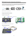
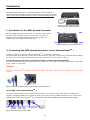
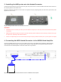
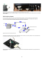
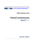
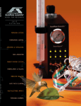
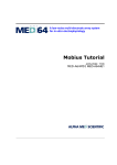
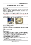
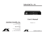
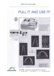
A low‐noise multi‐electrode array system for in vitro electrophysiology
Product Manual
MED Heated Connector
P/N: MED-CP02H
For the serial# smaller
than 2013CD01034
Information in this document is subject to change without notice.
No part of this document may be reproduced or transmitted
without the expressed written permission of Alpha MED Scientific
Inc.
While every precaution has been taken in the preparation of this
document, the publisher and the authors assume no responsibility
for errors, omissions, damages resulting from the use of
information contained in this document, or from the use of
programs and source code that may accompany it. In no event
shall the publisher and/or the author be liable for losses of profit
or any other commercial damage caused or alleged to have been
caused directly or indirectly by this document.
© 2013 Alpha MED Scientific Inc. All rights reserved
Version: 0.12; June 1, 2013
Alpha MED Scientific Inc.
Saito Bio-Incubator 209, 7-7-15, Saito-asagi,
Ibaraki, Osaka 567-0085, Japan
E-mail: [email protected]
Website: http://www.med64.com
Table of Contents
MED Heated Connector Components and Functions
2
Installation 3
1. Orientation of the MED Heated Connector
3
2. Connecting the MED Heated Connector to the ThermoClampTM-1
3. Installing the MED Probe onto the Heated Connector
4
4. Connecting the MED Heated Connector to the
MED64 Head Amplifier 4
With Perfusion system 5
5. Instruction for use
6
Setting temperature 6
Recommended temperature and important notice to achieve
temperature stability 6
Maintenance
7
Replacement of the tube incorporated into the heater unit
Cleaning of contact pins 7
Sterilization 7
Storage 7
Cautions
7
8
The terminal arrangement of electrodes on the MED Probe and
the Heated Connector 8
Warranty
9
Specifications
10
1
3
MED Heated Connector Components and Functions
The MED Heated Connector (MED-CP02H) functions to connect the MED Probe to the MED64 Head Amplifier (64CHANNEL HEAD AMPLIFIER, MED-A64HE1). Heater and thermocouple are incorporated into the bottom unit
(heater unit), which will warm and maintain the bath temperature on the MED Probe controlled by
ThermoClampTM -1 manufactured by AutoMate Scientific.
Digitizer
Stimulator
MED Probe
MED Heated Connector
MED64 Head Amp.
MED64 Main Amp.
PC and Mobius software
Fig. 1. System diagram for the MED64 System.
Components and their functions
Connector unit (top unit)
Grounding wire
68-pin terminals
Lock Screw
Contact pins
Guide Pin
Fig. 2. Connector unit. Top view (left) and bottom view (right).
Heater unit (bottom unit)
Perfusion tube port
Guide hole
Fig. 3. Heater unit.
2
Installation
The MED Heated Connector is compatible with the ThermoClampTM-1
manufactured by AutoMate Scientific. Please refer to the product manual
(http://autom8.com/pdfs/temperature/ThermoClamp%20Manual.pdf) for
instructions for the ThermoClampTM-1.
Fig. 4. The MED Heated Connector
.
connected
to the ThermoClampTM-1.
1. Orientation of the MED Heated Connector
Ch1
Ch8
Place the MED Heated Connector with its connector terminal and
connector cable oriented towards the right side. Channel 1 is
assigned to the top-left while channel 64 is assigned to the
bottom-right on the MED Heated Connector.
Ch57
Ch64
Fig. 5. Orientation for the MED Connector.
2. Connecting the MED Heated Connector to the ThermoClampTM-1
Connect 3 plugs to the ports on the ThermoClampTM-1 Temperature Controller.
Connect the blue plug with thin copper cable to the “Bath TC” port (left), the blue plug with thick brown cable to
the “Pencil TC” port (right), and the PS/2 plug to the “Heater Power” port. (Refer to Fig. 6)
For the MED Heated Connector which serial number is smaller than 2012LB01020:
Connect the blue plug with thin copper cable to the “Pencil TC” port (right), the blue plug with thick brown cable
to the “Bath TC” port (left).
CAUTION:
Place the ThermoClampTM-1 AWAY from the MED Heated Connector or MED Connector Cable to avoid generation
of noise.
Fig. 6. Connecting the MED Heated Connector to the ThermoClampTM-1.
Grounding of the ThermoClampTM-1
Connect the power cable (3 pins) of the ThermoClampTM-1 to the same power strip where the MED Head
Amplifier and Main Amplifier are connected. When power plugs without a GND terminal are used, connect the
GND terminal of the ThermoClampTM-1 to the GND terminal for the MED64 Head Amplifier (MED-64HE1).
PC
Display
monitor
Head Main
Amp Amp
ThermoClamp
Peristaltic
Pump
Fig. 7. Grounding with the power cables.
3
3. Installing the MED probe onto the Heated Connector
Loosen the lock screws on the connector unit (top unit) and remove it. Place the MED Probe filled with solution in
the square guide on the heater unit.
Place the connector unit back on the heater unit (bottom unit) by aligning guide pins with their guide holes, and
tighten the lock screws.
Fig. 8. Installing the MED Probe onto the Heated Connector.
CAUTION:
•
DO NOT touch the contact pins with your bare hands or finger tips. This may cause rust and adversely affect
conduction.
•
Spilling liquid onto the pins will cause rust and adversely affect conduction. Be extremely careful not to get
the pins wet, especially with saline solution.
•
Avoid over-tightening the lock screws and pressing the spring-loaded contact pins or probe guide too tightly.
4. Connecting the MED Heated Connector to the MED64 Head Amplifier
Connect the MED Heated Connector to the [INPUT] terminal on the MED64 Head Amplifier (MED-A64HE1)
with the MED Connector Cable. The side of the connector cable that has a long ground cable should be
connected to the Head Amplifier so that the cable can be grounded.
GND
Fig. 9. Connection between the MED Heated Connector and MED64 Head Amplifier.
4
Fig. 10. (Left) Connection of the MED Heated Connector to the MED Connector Cable.
Fig. 11. (Right) Back side of the MED64 Amplifiers. The MED Connector Cable is grounded to the GND terminal on the MED64
Head Amplifier.
With Perfusion System
When the MED Heated Connector is used with perfusion system, connect perfusion inlet-outlet tubes to
the perfusion tube ports so that solution can be warmed before being sent to the MED Probe. (Refer to
Fig. 12.) Clean the tube with double distilled water after each experiment.
Out
In
Perfusion tube port
Perfusion cap
Fig. 12. Connection for the perfusion tubes.
Connect the grounding wire (green wire) attached to the connector unit to the platinum wire incorporated into
the perfusion cap for grounding. (Refer to Fig. 13)
Fig. 13. Perfusion cap placed onto the MED Probe. The platinum wire incorporated into the Perfusion cap is grounded to the
connector unit.
5
Instructions for use
Setting temperature
•
Temperature is set and controlled by the ThermoClampTM-1. Please read the manual before using it with the
MED Heated Connector.
Turn on the power switch of the ThermoClampTM-1 temperature controller which is connected to the MED
Heated Connector. The C1 button is colored green and the control panel on the ThermoClampTM-1 will display
the measured temperature (present temperature).
Change the set-point to the desired one with following procedure:
1. Press the SEL key and hold it until the SV light (red) turns on. Now the controller displays the set-point value.
2. With UP and DOWN keys, adjust the temperature to the desired value.
3. Press and hold the SEL key again until the SV light turns off. Now the controller displays the measured
temperature.
Fig. 14. ThermoClampTM-1 (left) and the control panel (right).
Recommended temperature and Important notice to achieve a stable
temperature
In order to avoid the fluctuation in temperature, please make sure to cover the MED Probe during your
experiments. (The plastic cap which comes with the Heated Connector or perfusion cap could be used.)
Place the MED Heated Connector away from the direct stream of an air-conditioning.
Our evaluation test has verified that <1.0 °C accuracy can be achieved in the following ranges of
temperatures with 1) the room temperature of 25 °C and 2) MED Probe covered from the top.
•
•
Without perfusion: 30-37 °C (RT:25 °C with top-cover)
With perfusion:
30-32 °C (RT:25 °C with top-cover)
*The top of MED Probe must be covered to achieve the accuracy.
6
Maintenance
Replacement of the tubes incorporated into the heater unit
Replace the tube regularly according to following procedures.
Specification
Tygon(R) R3603 AAC00001 (ID:1/32 inches, OD:3/32 inches), 30 Cm long
Loosen the four screws and remove the aluminum plate from the heater base. (Fig. 15)
Fig. 15. Removing the aluminum plate from the heater base.
Remove the tube.
Fig. 16. Removing the tube.
Embed the new tube into the groove. Make sure that the tube is NOT twisted within the groove.
Return the aluminum plate onto the heater base and then tighten the screw. Check whether solution flows
smoothly with the new tube before starting your experiment.
Fig. 17. The aluminum plate returned.
7
Cleaning of contact pins
Wipe the contact pins several times while pushing them with a lint-free cloth. (e.g. Lens cloth for glasses).
If some contact pins are stuck and unmovable, contact your local distributor or our technical support
team.
Fig. 18. Cleaning the contact pins.
Sterilization
Wipe with a lint-free cloth soaked in 70% ethanol, and allow to dry.
CAUTION:
•
•
Do NOT autoclave as it may damage the MED Connector.
Do NOT wipe the contact pins with a cloth soaked with ethanol.
Storage
Store in a cool dry area. Avoid exposure to high temperatures or humidity.
Cautions
•
DO NOT touch the contact pins on the connector unit with bare hands or fingertips. This may cause rust and
adversely affect conduction.
•
DO NOT spill medium or any other liquid on the contact pins.
If you spill medium or any other liquid on the contact pins, immediately wipe them gently with a clean cloth
soaked with double-distilled water to remove any sediment or salts, and then allow to dry.
Avoid using alcohol. Alcohol may remove the lubricant which is necessary for the pins to move.
•
Do NOT press the contract pins and probe guide excessively. It may damage and affect conduction.
•
DO NOT give strong mechanical shock by putting heavy material on the unit or dropping the unit.
•
DO NOT tighten the lock screws excessively to avoid damaging them.
(The torque of the screw should not exceed 8kg.cm.)
•
Make sure to cover the MED Probe to achieve the <1.0 °C accuracy when used.
8
The terminal arrangement of electrodes on the MED probe and
the MED Heated Connector
Electrode Orientation
Once the MED Probe is set in the MED Heated Connector, channel 1 is located on the top left and channel 64 on
the bottom right when the connector terminal is located on the right hand side (as shown in the figure below).
This channel arrangement is the same even if the probe is rotated 90 or 180 degrees, since the channel number
is relative to it's location in the MED Heated Connector.
Reference electrodes
Four reference electrodes are connected to the terminal connector separately.
1
8
57
64
60
36
53
45
54
63
64
56
47
48
39
40
32
31
24
23
15
8
19
18
27
26
28
33
35
41
49
50
7
22
6
21
5
29
Reference electrodes (R)
52
44
61
59
62
51
55
43
46
58
38
(R) bottom-left
37
(R) upper-left
30
(R) bottom -right
16
(R) upper-right
9
1
17
10
25
2
34
11
42
3
57
20
14
12
13
4
68-pin terminals layout
Fig. 19. Electrode orientation on the MED probe (left) and 68pin terminals layout (right)
9
Warranty
This product will be repaired with new or refurbished parts, free of charge, for one (1) year from the date of
original purchase in the event of a defect in materials or workmanship.
The product warranty covers failures due to defects in materials or workmanship which occur during normal use.
It does NOT cover damage incurred during shipment or problems which are caused by products not supplied by
Alpha MED Scientific. In addition, this warranty does not cover problems resulting from alteration, accident,
misuse, neglect, faulty installation, maladjustment of user controls, improper maintenance, modifications or
service by anyone other than AMS or damage attributable to acts of God.
Specifications
Connector unit
MED Probe securing mechanism
Screw down
Out put
68-pin terminals
Printed circuit board
4 layers (The 1st and 4th layers are ground, and 2nd
and 3rd layers contain signal line
Contact resistance
< 30mΩ
Heater unit
Heater devise
Transistor
Temperature accuracy
(for solution in the MED probe)
<1.0 °C
Range of verified <1.0 °C accuracy
30-37 °C (RT:25°C
30- 32 °C (RT:25°C
without perfusion / with top covered)
with perfusion/ with top covered)
General
Material
Aluminum. Gold plate for contact pins
Cables length
80 Cm
Weight
700 g
Dimensions
W174 x H38 x D150 mm
Specifications may not be satisfied depending upon the type of computer or operating environments used.
Only for use in animal studies research.
Specifications and external appearance are subject to change without notice.
ThermoClampTM-1 is a trade mark for AutoMate Scientific, Inc.
10
MED-CP02H (ver.1-2)
June 1, 2013
Alpha MED Scientific Inc.
Manufactured by Alpha MED Scientific Inc.
©2013 Alpha MED Scientific Inc.
Saito Bio-Incubator 209, 7-7-15, Saito-asagi,
Ibaraki, Osaka 567-0085, Japan
Phone: +81-72-648-7973 FAX:+81-72-648-7974
http://www.med64.com [email protected]