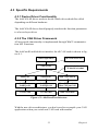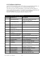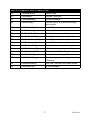
1
PCI-1680U
2-Port CAN Interface Universal
PCI Communication Card w/Isolation
User Manual
Copyright
The documentation and the software included with this product are copyrighted 2004 by Advantech Co., Ltd. All rights are reserved. Advantech
Co., Ltd. reserves the right to make improvements in the products
described in this manual at any time without notice. No part of this manual may be reproduced, copied, translated or transmitted in any form or
by any means without the prior written permission of Advantech Co., Ltd.
Information provided in this manual is intended to be accurate and reliable. However, Advantech Co., Ltd. assumes no responsibility for its use,
nor for any infringements of the rights of third parties, which may result
from its use.
Acknowledgements
Intel and Pentium are trademarks of Intel Corporation.
Microsoft Windows is a registered trademark of Microsoft Corp.
All other product names or trademarks are properties of their respective
owners.
Part No. 2003168000
1st Edition
Printed in Taiwan
November 2004
PCI-1680U User Manual
ii
Product Warranty (2 years)
Advantech warrants to you, the original purchaser, that each of its products will be free from defects in materials and workmanship for two years
from the date of purchase.
This warranty does not apply to any products which have been repaired or
altered by persons other than repair personnel authorized by Advantech,
or which have been subject to misuse, abuse, accident or improper installation. Advantech assumes no liability under the terms of this warranty as
a consequence of such events.
Because of Advantech’s high quality-control standards and rigorous testing, most of our customers never need to use our repair service. If an
Advantech product is defective, it will be repaired or replaced at no
charge during the warranty period. For out-of-warranty repairs, you will
be billed according to the cost of replacement materials, service time and
freight. Please consult your dealer for more details.
If you think you have a defective product, follow these steps:
1.
Collect all the information about the problem encountered. (For
example, CPU speed, Advantech products used, other hardware
and software used, etc.) Note anything abnormal and list any
onscreen messages you get when the problem occurs.
2.
Call your dealer and describe the problem. Please have your manual, product, and any helpful information readily available.
3.
If your product is diagnosed as defective, obtain an RMA (return
merchandize authorization) number from your dealer. This allows
us to process your return more quickly.
4.
Carefully pack the defective product, a fully-completed Repair and
Replacement Order Card and a photocopy proof of purchase date
(such as your sales receipt) in a shippable container. A product
returned without proof of the purchase date is not eligible for warranty service.
5.
Write the RMA number visibly on the outside of the package and
ship it prepaid to your dealer.
iii
CE
This product has passed the CE test for environmental specifications
when shielded cables are used for external wiring. We recommend the use
of shielded cables. This kind of cable is available from Advantech. Please
contact your local supplier for ordering information.
Technical Support and Assistance
Step 1. Visit the Advantech web site at www.advantech.com/support
where you can find the latest information about the product.
Step 2. Contact your distributor, sales representative, or Advantech's customer service center for technical support if you need additional
assistance. Please have the following information ready before
you call:
- Product name and serial number
- Description of your peripheral attachments
- Description of your software (operating system, version, application software, etc.)
- A complete description of the problem
- The exact wording of any error messages
Packing List
Before setting up the system, check that the items listed below are
included and in good condition. If any item does not accord with the
table, please contact your dealer immediately.
• PCI communication interface card
• Industrial Communication Driver, Utility and PCI communication card
user's manual in ICOM CD-ROM
PCI-1680U User Manual
iv
Contents
Chapter
1 Introduction ..................................................... 2
1.1
1.2
1.3
1.4
Chapter
Features ............................................................................. 3
Specifications .................................................................... 3
Ordering Information ........................................................ 4
Advantech Device Manager Installation ........................... 6
Driver Installation ........................................................... 14
3 Hardware Installation................................... 18
3.1
3.2
Initial Inspection.............................................................. 18
Jumper Locations & Setting............................................ 19
3.2.1
3.2.2
3.3
Chapter
Figure 3.1:PCI-1680U Silk Screen .............................. 19
How to Set Jumpers ..................................................... 20
Figure 3.2:How to Set Jumpers .................................... 20
Terminator Resistor Setup ........................................... 20
Table 3.1:PCI-1680U Terminator Resistor Reference 20
Card Installation .............................................................. 21
4 Software Requirements ................................ 24
4.1
Introduction ..................................................................... 24
4.2
4.3
Overall Description ......................................................... 24
Specific Requirements..................................................... 25
4.1.1
4.1.2
4.3.1
4.3.2
4.3.3
Chapter
Controller Area Network ............................................... 2
Universal PCI ................................................................. 2
Optical Isolation Protection ........................................... 2
2 Installation of Driver and Device Manager .. 6
2.1
2.2
Chapter
Description ........................................................................ 2
1.1.1
1.1.2
1.1.3
Definitions, Acronyms, and Abbreviations ................. 24
Reference ..................................................................... 24
Device Driver Functionality ........................................ 25
The CAN Driver Framework ....................................... 25
Figure 4.1:AdsCan.dll architecture .............................. 25
Software Interfaces ..................................................... 26
Table 4.1:Function Table of AdsCAN.dll ................... 26
5 Pin Assignments and Wiring ....................... 30
5.1
Pin Assignments.............................................................. 30
5.2
Wiring.............................................................................. 30
Figure 5.1:PCI-1680U DB-9 pin assignment .............. 30
Table 5.1:PCI-1680U Pin Wiring and Description ...... 30
v
PCI-1680U User Manual
vi
CHAPTER
1
2
Introduction
This chapter provides a general
description of the PCI-1680U.
Sections include:
• Description
• Features
• Specifications
• Ordering Information
Chapter 1 Introduction
1.1 Description
PCI-1680U is special purpose communication card that offers connectivity to Controller Area Networks (CAN) on your PC. With its built-in
CAN controllers, the PCI-1680U provides bus arbitration and error detection with an automatic transmission repetition function. This drastically
reduces the chance of data loss and ensures system reliability. You can
run both CAN controllers independently at the same time. The PCI1680U operates at baud rates up to 1 Mbps and can be installed in a PC
expansion slot.
1.1.1 Controller Area Network
The CAN (Controller Area Network) is a serial bus system especially
suited for networking "intelligent" I/O devices as well as sensors and
actuators within a machine or plant. Characterized by its multi-master
protocol, real-time capability, error correction, high noise immunity, and
the existence of many different silicon components, the CAN serial bus
system, originally developed by Bosch for use in automobiles, is increasingly being used in industrial automation.
1.1.2 Universal PCI
PCI-1680U provides truly universal connectivity, enabling a single product to be used to implement systems with dramatically different resource
requirements. This makes PCI-1680U the most robust, most flexible, and
most economical choice for any application requiring isolation. PCI1680U uses a universal PCI connector compatible with both new 3.3 V
signaling support required for plug-in boards by the PCI 2.2 specification
and the 5 V signaling still used by many systems.
1.1.3 Optical Isolation Protection
On-board optical isolators protect your PC and equipment against damage from ground loops, increasing system reliability in harsh environments.
PCI-1680U User Manual
2
1.2 Features
• PCI bus specification 2.2 compliant
• Operates two separate CAN networks at the same time
• High speed transmission up to 1 Mbps
• 16 MHz CAN controller frequency
• Optical isolation protection of 1000 VDC ensures system reliability
• I/O address automatically assigned by PCI PnP
• LED indicates Transmit/Receive status on each port
• Windows DLL library and examples included
• Supports Windows 98/ME/2000/XP driver and utility
• Universal PCI
1.3 Specifications
• Bus Interface: PCI bus spec. 2.2 compliant
• Ports: 2
• Protocol: CAN 2.0 A/B
• Communication Controller: SJA-1000
• CAN Transceiver: 82C250
• Signal Support: CAN_H, CAN_L
• CAN Controller Frequency: 16 MHz
• Speed (bps): Up to 1 Mbps programmable transfer rate
• Isolation Protection: 1,000 V DC
• Connector: Dual DB9 male connectors
• Power Consumption: 5 V @ 400 mA(Typical)
• Dimensions: 185 x 100 mm
• Operating Temperature: 0 ~ 60° C
• Storage Temperature: -25 ~ 85° C
• Operating Humidity: 5 ~ 95% Relative Humidity, non-condensing
3
Chapter 1
1.4 Ordering Information
PCI-1680U: 2-port CAN interface universal PCI communication card
w/isolation.
PCI-1680U User Manual
4
CHAPTER
2
2
Installation of Driver
and Advantech Device
Manager
This chapter shows how to install the
driver and Advantech Device Manager.
Sections include:
• Driver Installation
• Advantech Device Manager Installation
Chapter 2 Installation of Driver and
Advantech Device Manager
2.1 Advantech Device Manager Installation
Advantech Device Manager is a software program that allows you to configure your hardware and store the settings in your Windows registry. You
must install the Advantech Device Manager if you want to add and manage Advantech CAN cards.
Please follow the steps below to install Advantech Device Manager.
1.
Click the Installation button for installation.
PCI-1680U User Manual
6
2.
Click the CAN Card Drivers button to enter the CAN cards selection screen.
3.
Click the Install Advantech Device Manager hyperlink to install
Advantech Device Manager.
7
Chapter 2
4.
The InstallShield Wizard wil initiate the installation process..
PCI-1680U User Manual
8
5.
Click Next to start the install process.
6.
Click Yes if you accept the License Agreement.
9
Chapter 2
7.
Type user name and company name, and then click Next.
8.
Click Next to accept the default installation folder, or you can specify a folder by clicking the Browse button.
PCI-1680U User Manual
10
9.
Choose the type of setup you prefer, then click Next.
10.
Setup will add program icons to the default program folder. You
may type a new folder name, or select one from the existing folder
list. Click Next to continue.
11
Chapter 2
11.
Click Back to review or change your settings. Click Next, and the
installation program will copy the files to your computer to finish
the installation process.
PCI-1680U User Manual
12
12.
You can see that shortcuts that were added to your Windows Start
Menu.
13.
After the physical hardware has been installed, execute Advantech
Device Manager to see PCI-1680U in both Installed Devices &
Support Devices windows. You can get the device number for
AdsCAN.dll compiler. Click the Setup button for each port setting.
13
Chapter 2
2.2 Driver Installation
Please follow the steps below for PCI-1680U driver installation.
1.
Insert your companion CD-ROM disc into your CD-ROM drive
2.
The driver setup program will be launched automatically. If the
auto-play function is not enabled on your system, use Windows
Explorer or the Windows Run command to execute autorun.exe on
the companion CD-ROM.
3.
Click the Installation button to start installation.
PCI-1680U User Manual
14
4.
Click the CAN Card Drivers button to enter the CAN cards selection screen.
5.
Choose the card you want to install (PCI-1680U), and then click
the hyperlink.
15
Chapter 2
6.
Click Next, and the Advantech Device Driver will be automatically
installed on your computer.
7.
After the physical hardware has been installed, the card will be
automatically detected.
PCI-1680U User Manual
16
CHAPTER
3
2
Hardware Installation
This chapter covers inspection and
installation of hardware and drivers.
Sections include:
• Initial inspection
• Jumper locations & setting
• Card installation
Chapter 3 Hardware Installation
3.1 Initial Inspection
You should find the following items inside the shipping package:
• PCI communication interface card
• Industrial Communication Driver, Utility and PCI communication card
user's manual in ICOM CD-ROM
PCI-1680U was carefully inspected mechanically and electrically before
it was shipped. It should be free of marks and scratches and in perfect
working order when received.
As you unpack the PCI-1680U, check for signs of shipping damage (damaged box, scratches, dents, etc.). If it is damaged or it fails to meet specifications, notify our service department or your local sales representative
immediately. Also notify the carrier. Retain the shipping carton and packing material for inspection by the carrier. After inspection we will make
arrangements to repair or replace the unit.
When you handle the PCI-1680U, remove it from its protective packaging by grasping the rear metal panel. Keep the anti-vibration packing.
Whenever you remove the card from the PC, store it in this package for
protection.
Warning!
Discharge your body’s static electric charge by
touching the back of the grounded chassis of the
system unit (metal) before handling the board. You
should avoid contact with materials that hold a static
charge such as plastic, vinyl and Styrofoam. Handle
the board only by its edges to avoid static damage to
its integrated circuits. Avoid touching the exposed
circuit connectors. We also recommend that you use
a grounded wrist strap and place the card on a static
dissipative mat whenever you work with it.
PCI-1680U User Manual
18
3.2 Jumper Locations & Setting
Figure 3.1: PCI-1680U Silk Screen
19
Chapter 3
3.2.1 How to Set Jumpers
You configure your card to match the needs of your application by setting
jumpers. A jumper is the simplest kind of electric switch. It consists of
two metal pins and a small metal clip (often protected by a plastic cover)
that slides over the pins to connect them. To “close” a jumper you connect the pins with the clip. To “open” a jumper you remove the clip.
Figure 3.2: How to Set Jumpers
3.2.2 Terminator Resistor Setup
You can set the terminator resistor if necessary to match impedance. Each
port has a separate resistor.
Table 3.1: PCI-1680U Terminator Resistor Reference
Status
Value of Terminator Resistor()
Open mode
0
Close mode
120
PCI-1680U User Manual
20
3.3 Card Installation
Note:
Warning!
Make sure you have installed the driver before
installing the card. We strongly recommend
that you install the software driver before
installing the hardware into your system, since
this will guarantee a smooth and trouble-free
installation process.
Turn off your PC’s power supply whenever you
install or remove the PCI communication card or its
cables. Static electricity can easily damage computer equipment. Ground yourself by touching the
chassis of the computer (metal) before you touch
any boards.
1.
Turn off the computer.
2.
Turn the power off to any peripheral devices (such as printers and
monitors).
3.
Disconnect the power cord and any other cables from the back of
the computer.
4.
Turn the PC if necessary to gain access to the cables.
5.
Remove the PC’s cover (refer to your user’s guide if necessary).
6.
Locate the expansion slots or passive back-plane (at the rear of the
PC) and choose any unused slot.
7.
Remove the screw that secures the expansion slot cover to the PC
(save the screw to secure the interface card retaining bracket).
8.
Remove the anti-vibration card clamp if supplied.
9.
Carefully grasp the upper edge of the PCI communication card.
10.
Align the hole in the retaining bracket with the hole on top of the
expansion slot.
11.
Align the gold striped edge connector with the expansion slot
socket.
12.
Press the board firmly into the socket.
13.
Replace the screw in the expansion slot’s retaining bracket.
21
Chapter 3
14.
Replace anti-vibration cardholder.
15.
Replace the PC’s cover. Connect the cables you removed in step 3.
16.
Turn the computer power on.
17.
The board is now installed in the computer. See Chapter 5 for information on cabling.
PCI-1680U User Manual
22
CHAPTER
4
2
Software
Requirements
This chapter has information on the
software of PCI-1680U.
Sections include:
• Introduction
• Overall Description
• Specific Requirements
Chapter 4 Software Requirements
4.1 Introduction
PCI-1680 and PCL-841 are Isolated Dual-port CAN communication
cards. Each provides two isolated CAN ports for communication applications in difficult environments. The chip on the CAN cards is SJA1000.
The SJA1000 is a single chip solution for PC-based CAN port and parallel expansion add-in cards.
This chapter outlines the CAN card’s windows DLL driver software
requirement specifications. Including functionality, performance, and
user interface requirements. It applies to programming the CAN cards
Windows unified DLL driver, including the driver for PCL841 and
PCI1680.
4.1.1 Definitions, Acronyms, and Abbreviations
SRS = Software Requirements Specification
PPI = Programmable Peripheral Interface
GUI = Graphics User Interface
4.1.2 Reference
Please see “SJA1000.pdf” on your CD-ROM for further information on
the SJA1000 chip.
4.2 Overall Description
In order to unify the driver interface of Advantech’s CAN series of products, a new DLL file named AdsCAN.dll has been defined. This makes it
possible to change the CAN card from PCI-1680 to PCL-841 without
recompiling applications.
AdsCAN.dll should decide which driver to call depending on the different CAN cards.
PCI-1680U User Manual
24
4.3 Specific Requirements
4.3.1 Device Driver Functionality
The AdsCAN.dll driver needs to decide which driver should be called
depending on different hardware.
The AdsCAN.dll driver should properly translate the function parameters
to a lower layer driver.
4.3.2 The CAN Driver Framework
All user-mode functionality is implemented through Win32 communication API Functions.
The AdsCan.dll unified driver interface for all CAN cards is shown in figure 4.1.
User's Application
AdsCAN.dll
Call CAN win32 API
Dynamic decide which
dll should be loaded
Ads841.dll
Ads1680.dll
Other CAN card dll
Ads841s.sys
Ads841s.vxd
Ads1680s.sys
Ads1680s.vxd
Other CAN card sys
Other CAN card vxd
PCL841 card
PCI1680 card
Other CAN cards
Figure 4.1: AdsCan.dll architecture
With the new driver architecture, you don’t need to recompile your CAN
applications when you switch one CAN card with another.
25
Chapter 4
4.3.3 Software Interfaces
AdsCAN.dll should follow the CAN software-programming interface, so
that users can use Advantech’s driver software in the same way.
You can access the CAN functionality via the AdsCAN.dll Library as
shown in the following table. For detailed function library definitions and
descriptions please see the file ‘can.chm’ on the CD-ROM.
Path in CD-ROM: Documents\Software Manuals\CAN
Table 4.1: Function Table of AdsCAN.dll
Function
Syntax (in C)
Description
1
CANCheckEvent()
Check event status from kernelmode and clear event.
2
CANEnableEvent()
Enables or disables the event mechanism
3
CANEnableMessaging()
Select the data transmit interrupt
4
CANEnableRxInt()
Enable the receive interrupt
5
CANGetArbitrationLostCatchMsgEx()
Get arbitrate lost catch information
6
CANGetBaudRate()
Get the card current baud rate
7
CANGetControllerErrorCodeEx()
Get Controller error code
8
CANGetErrorMessage()
Get error message
9
CANGetEventName()
Queries and gets CAN port's event
name
10
CANGetProtocolType()
Get the card current protocol type
11
CANHwReset()
Reset the hardware
12
CANInit()
Controls CAN port settings
13
CANInpb()
Inputs a byte data from the specified
address on CAN card
14
CANOutpb()
Outputs a byte data to the specified
address on CAN card
15
CANPortClose()
Releases settings, close port
16
CANPortOpen()
Open the CAN port
17
CANQueryID()
Query the message ID
18
CANQueryMsg ()
Reads data from the card
PCI-1680U User Manual
26
Table 4.1: Function Table of AdsCAN.dll
19
CANReadFile()
Reads data
20
CANReset()
Resets CAN port
21
CANSendMsg()
Sends message
22
CANSetAcp()
Set the card 2.0 A protocol acceptance code
23
CANSetAcpEx()
Set 2.0B protocol accept code
24
CANSetBaud()
Set card baud rate
25
CANSetBufferPtr()
Set the data receive buffer
26
CANSetCountPtr()
Set the counter of receive buffer
27
CANSetIntrMaskEx()
Set 2.0B protocol interrupt mask
28
CANSetNormal()
Sets CAN card to normal mode
29
CANSetOutCtrl()
Set the card out control register
30
CANSetProtocolType()
Set the card current protocol type
31
CANWaitForFIFOEvent()
Wait for the FIFO buffer event.
32
CANWaitForID()
Wait For the message ID
33
CANWaitForMsg()
Queries and gets message from
CAN bus.
34
CANWakeUpEx()
Set Can controller into sleep mode
35
CANWriteFile()
Send message
27
Chapter 4
PCI-1680U User Manual
28
CHAPTER
5
2
Pin Assignments and
Wiring
This chapter covers the pin assignment
for the CAN connector, and the wiring
of the two transmission wires.
Sections include:
• Pin Assignments
• Wiring
Chapter 5 Pin Assignments and Wiring
5.1 Pin Assignments
Figure 5.1 shows the pin assignment for the card’s DB-9 connectors
Figure 5.1: PCI-1680U DB-9 pin assignment
5.2 Wiring
The CAN standard supports half–duplex communication. This means that
just two wires are used to transmit and receive data.
Table 5.1: PCI-1680U Pin Wiring and Description
PCI-1680U DTE (male DB-9) Terminal DTE
Pin
Signal
Signal
2
CAN_L
CAN_L
3
GND
GND
7
CAN_H
CAN_H
PCI-1680U User Manual
30