1
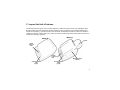
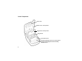
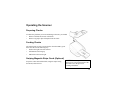
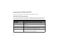
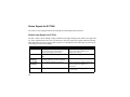
EC6000i®, EC7000i®, and EC7500i®
Series Installation Guide
This manual, the EC6000i , EC7000i, and EC7500i Series Installation Guide, is intended for all units
belonging to the EC6000i, EC7000i, and EC7500i family of products.
EC6000i, EC7000i, EC7500i, ITMS, RDM, and the RDM logo are all registered trademarks of RDM
Corporation. All other brand names and trademarks appearing in this guide are the property of their
respective holders.
Copyright© RDM Corporation, 2012
All rights reserved. No part of this document may be reproduced in any form without the written consent of RDM Corporation.
Part Number: 302665
Revision: D
Contents
Compliance Statements .................................................................. 2
Introduction ..................................................................................... 4
Requirements .................................................................................. 5
Setting Up the EC6000i, EC7000i, or EC7500i ............................... 6
Operating the Scanner .................................................................. 15
Maintaining the EC6000i, EC7000i, or EC7500i ........................... 20
Troubleshooting ............................................................................ 22
Specifications ................................................................................ 25
Warranty Information ..................................................................... 28
1
Compliance Statements
FCC Compliance Statement
NOTE for EC6000i , EC7000i, and EC7500i Series Scanners: This equipment has been tested and found to comply with the limits for a Class
A digital device, pursuant to part 15 of the FCC Rules. These limits are designed to provide reasonable protection against harmful interference
when the equipment is operated in a commercial environment. This equipment generates, uses, and can radiate radio frequency energy and, if not
installed and used in accordance with the instruction manual, may cause harmful interference to radio communications. Operation of this
equipment in a residential area is likely to cause harmful interference in which case the user will be required to correct the interference at his/her
own expense.
Models with internal modem: This equipment complies with Part 68 of the FCC rules and the requirements adopted by the ACTA. On the
bottom of this equipment is a label that contains, among other information, a product identifier in the format “US: AAAEQ##TXXX”. If
requested, this number must be provided to the telephone company.
A plug and jack used to connect this equipment to the premises wiring and telephone network must comply with the applicable FCC Part 68
rules and requirements adopted by the ACTA. A compliant telephone cord and modular plug is provided with this product. It is designed to be
connected to a compatible modular jack that is also compliant. See installation instructions for details.
The Ringer Equivalence Number (or REN) is used to determine the number of devices that may be connected to a telephone line. Excessive
RENs on a telephone line may result in the devices not ringing in response to an incoming call. In most but not all areas, the sum of RENs
should not exceed five (5.0). To be certain of the number of devices that may be connected to a line, as determined by the total RENs, contact
the local telephone company. For products approved after July 23, 2001, the REN for the product is part of the product identifier that has the
format “US: AAAEQ##TXXX”. The digits represented by ## are the REN without a decimal point (e.g. 03 is a REN of 0.3; 00 is a REN of 0.0).
For earlier products, the REN is separately shown on the label.
If this equipment causes harm to the telephone network the telephone company will notify you in advance that temporary discontinuance of the
service may be required. But if advance notice isn’t practical the telephone company will notify the customer as soon as possible. Also, you will
be advised of your right to file a complaint with the FCC if you believe it is necessary.
2
The telephone company may make changes in its facilities, equipment, operations or procedures that could affect the operation of this
equipment. If this happens the telephone company will provide advanced notice in order for you to make necessary modification to maintain
uninterrupted service.
Connection to party line service is subject to state tariffs. Contact the state public utility commission, public service commission or corporation
commission for information.
If your home has specially wired alarm equipment connected to the telephone line ensure the installation of this scanner does not disable oyour
alarm equipment. If you have questions about what will disable alarm equipment, consult your telephone company or a qualified installer.
CAUTION: Changes or modifications not expresssly approved by RDM Corporation could void the user’s authority to operate the
equipment.
All units covered by this manual have no user-serviceable parts inside. In the event repairs are ever needed to any RDM product, they should be
performed by RDM Corporation or an authorized representative of RDM Corporation. For information please contact RDM Corporation,
4-608 Weber Street North, Waterloo, Ontario, Canada N2V 1K4, at 1-800-567-6227, or RDM’s US service agent below.
US Service Agent
William Buser
(703) 286-5734
[email protected]
Industry Canada Compliance Statement
This product meets the applicable Industry Canada technical specifications/Le présent materiel est conforme aux specifications techniques
applicables d’Industrie Canada.
The Ringer Equivalence Number is an indication of the maximum number of devices allowed to be connected to a telephone interface. The
termination on an interface may consist of any combination of devices subject only to the requirement that the sum of the RENs of all the devices
does not exceed five/L’indice d’équivalence de la sonnerie (IES) sert à indiquer le nombre maximal de terminaux qui peuvent être raccordés à
une interface téléphonique. La terminaison d’une interface peut consister en une combinaison quelconque de dispositifs, à la seule condition que
la somme d’indices d’équivalence de la sonnerie de tous les dispositifs n’excède pas 5.
For information contact: RDM Corporation, 4-608 Weber Street North, Waterloo, Ontario, Canada N2V 1K4
3
Introduction
The EC6000i®, the EC7000i®, and the EC7500i® Series Scanners are cost effective, feature rich, imaging
solutions. Using RDM’s industry leading progressive MICR method and imaging technology, the EC6000i,
the EC7000i, and the EC7500i Series Scanners are ideal for Check Electronification, Check Cashing, and
Walk-in Bill Payment applications.
4
Requirements
•
•
The EC6000i, the EC7000i, and the EC7500i units are for indoor use only. Keep the EC6000i, the
EC7000i, and the EC7500i dry; avoid areas of high humidity.
Do not remove any cabinetry other than the areas specified in this guide. Removing cabinetry other
than the areas specified in this guide will void the warranty.
Recommendations
•
•
•
This unit may be installed and programmed by a distributor (reseller) other than the original
manufacturer. Record all distributor contact information for future reference.
Save the original box and packing material. Reuse them if the unit must be shipped to a new location.
Position the unit so that the operator has easy access to the check path and a clear view of the LED. Do
not put the unit close to a heat source, in direct sunlight, or close to any device that can emit
electromagnetic interference, such as a computer monitor or power adapter.
5
Setting Up the EC6000i, EC7000i, or EC7500i
To set up the EC6000i, the EC7000i, and the EC7500i,
follow steps A – H.
A. Choose a Location
Locate your scanner in a place that:
• has a flat surface, such as a countertop or table
• is convenient for the scanner operator
• offers adequate ventilation and protection from
elements such as heat, dust, oil, or moisture
• is close to a telephone line or network connection
(depending on your unit) and power connections.
B. Unpack the Shipping Box
1.
2.
3.
6
Open the top of the box.
Remove and unwrap the items.
Save the box and wrapping for future use.
NOTE: Before unpacking the box, examine
it for damage received during shipping. If
the scanner, or any component, appears
damaged, do not use it. File a claim with the
shipping company and contact your
distributor.
Your EC6000i, EC7000i, or EC7500i
product package includes the following:
• The EC6000i, the EC7000i, or the
EC7500i scanner
• Power adapter
• Telephone line (optional with modem) EC6000i or EC7000i only
• Franking Acknowledgement Printer
Cartridge (optional) Reorder P/N 6000-6050
• USB cable
C. Inspect the Unit’s Features
The illustrations below show a basic scanner (Model A), and an EC7500i scanner with a Magnetic Stripe
Reader (MSR) and printer (Model B). Scanner Model A will be graphically represented throughout this
manual for consistency. All other features of the EC6000i, the EC7000i, and the EC7500i are available as
standard or optional. All EC7500i series models are franker-enabled. Specific EC6000i and EC7000i series
models have franking capability.
Model B
Model A
Printer
Check
Insertion
Slot
Check
Insertion
Slot
Scanner Status
LED
(Light)
Magnetic Stripe
Reader
Scanner Status
LED
(Light)
7
Inside Components
Cover Latch
Outside Cover in raised position
Image Frame in raised position
Image Sensor
Document Sensors
Document Feed Plate comes out to reveal optional
Franking Acknowledgement Printer Assembly
(EC6000i shown)
8
Connection Ports
RDM’s EC6000i, the EC7000i, and EC7500i can be installed in different configurations. These
configurations are set and programmed by the distributor (reseller) to suit your unique needs.
Follow instructions provided by your distributor (reseller).
EC6000i and EC7000i have the following ports:
EC6000i and EC7000i Connectors
Power:
USB:
AUX:
COM:
TEL:
Red. Connect the power adaptor to this
port.
Orange. Use this port to connect to a PC.
Yellow. Use this port to connect optional
peripheral devices such as a pass through
printer. (EC6000i, the EC7000i only)
Green. Use this port to connect to a PC or
terminal (EC6000i, the EC7000i only).
Purple. This port offers an optional modem
to be connected to a telephone line. Some
scanners may not contain a TEL Port
(EC6000i, the EC7000i only).
EC7500i Connectors
USB-B
Power
9
D. Insert the Franking Acknowledgement
Printer Cartridge (Optional)
The Franking Acknowledgement Printer Cartridge is an optional
ink stamp, that marks the front of each check with a
“Electronically Presented” message, or a message that you create.
If you have purchased this option, follow these directions to insert
the printer cartridge into the unit.
I. Access the Printer Assembly
1.
2.
3.
10
Press the latch and lift the cover to access the imaging
frame.
Lift the imaging frame to access the feed plate.
Locate the blue tab on the side of the unit.
a. With your thumb on the outside of the unit, apply
enough pressure to pull the blue tab towards the
outside of the unit and hold it there.
b. While holding the blue tab, lift the document feed
plate up and to the left or up and to the right to free
it from the opposite side.
c. Remove the plate completely. (continued...)
II. Insert the Franking Acknowledgement
Printer Cartridge into the Printer Assembly
1.
2.
3.
4.
5.
Insert the Franking Acknowledgment Printer
Cartridge straight into the printer assembly.
Apply pressure to the widest part of the flat top until
the cartridge clicks into place.
Replace the document feed plate by pressing down
firmly until it clicks into place.
Close the imaging frame.
Close the outside cover.
CAUTION:
• Avoid contact with the main drive roller to prevent ink
transfer to documents.
• Ink may be harmful if swallowed.
• Avoid contact with eyes.
• Damage to the unit or the cartridge resulting from
modifying the cartridge is not the responsibility of
RDM.
• The ink cartridge is not refillable.
• Not licensed for modifications.
11
E. Connect to a Telephone Line (EC6014 and EC7014)
FOR TEL: If you have purchased the EC6000i or the EC7000i with the optional modem, follow these
directions to connect the telephone line.
1. Insert the end of the telephone line into the TEL port on the back of the scanner.
2. Insert the other end of the telephone line into a telephone jack in the wall.
CAUTION: Plug the telephone line into an “outside line” analog phone jack only; the modem will not
work if it is plugged into a PBX digital line.
Test the Telephone Line and Third-Party Line
1.
2.
3.
12
Call the third-party line to ensure that it is working properly.
If the third-party line is not working, contact your local telephone company for repair.
If the telephone line works, contact your distributor to have the EC6000i or the EC7000i serviced.
F. Connect the Power Cord
1.
2.
3.
4.
Insert the round end of the power cord into the power port on the back of the scanner.
Align the flat side of the power connector facing up.
Plug the metal-pronged end of the power cord into an electrical power outlet.
When you connect to power, the LED lights up. Your unit is now powered on.
CAUTION: Disconnecting the power source while the terminal is processing a transaction may cause data
files stored in the unit’s memory to be lost.
NOTE: The power adaptor includes a locking mechanism that securely connects the power cord to the
scanner. To prevent cord damage, do not pull on the cord. Firmly slide back the locking mechanism before
disconnecting the power cord from the unit.
13
G. Drivers
The drivers for your scanner are installed when you install your PC application. If it is a Web-based
application, ActiveX may be installed. There are many applications that support RDM EC Series Scanners;
most are available from third-party vendors.
If you are not sure where to acquire your PC application, check with the reseller from whom you purchased
your scanner, your bank, or your service provider.
H. Install the Printer Paper Roll
EC Series Scanners that include a printer use single-ply, thermal-sensitive paper that comes in a roll that is
2.25 inches (5.8 cm) wide.
CAUTION: Handle thermal paper with care; friction, humidity, light, etc, will damage it. Do not load
paper with wrinkles, folds, or tears. For best results, cut the paper, rather than tearing it, to feed it into the
printer.
To install a roll of paper:
1. Ensure that scanner is powered on.
2. Swing open the clear plastic paper roll cover at the back of the unit.
3. Hold the paper roll with the paper feeding from the bottom and guide the straight-cut end of the
paper into the paper feed slot that is in line with the holder. The feed mechanism will start to pull
the paper into the unit.
4. Place the roll loosely into the paper roll holder.
5. Swing the paper roll cover back into place.
14
Operating the Scanner
Preparing Checks
To reduce the possibility of errors and damage to the unit, you should:
• Remove all folds and creases in the check.
• Remove any paper clips and staples from the check.
Feeding Checks
The scanner unit is ready to accept checks when the LED is green.
Insert the check in the following way:
• Flush to the right side of the scanner.
• Information-side facing up.
• MICR line to the inside right.
Swiping Magnetic Stripe Cards (Optional)
Swipe the credit card with the black, magnetic stripe facing
downward, and to the left.
CAUTION: Do not open the cover or
otherwise try to access the inside of the
unit while it is in the process of
scanning a document.
15
Status Signals for EC6000i and EC7000i
The scanner comes equipped with the default light and sound signals described below.
EC6000i/EC7000i Default Light Signals
The unit’s status is shown through a single, multi-state LED (light-emitting diode), which is the light on the
top, front, right-hand side of the unit. The table below describes typical status signals and their meanings.
LED
Green Solid
Green Flashing
Amber Solid
Amber Flashing
Red / Green / Amber Flashing
Red Solid
Red Flashing
16
Meaning; What To Do
The unit is ready to accept a check; insert a check.
The unit is busy, processing the last check; wait for the job to finish.
The unit is idle; start the next job with a command from the terminal or PC
application.
The unit is sending or receiving information from the terminal or PC
application; wait.
The unit is starting up or performing diagnostics; wait.
The unit failed during a self-test; check the terminal display for instructions /
refer to your local procedures / call you distributor (reseller).
An error occurred during processing. See “Default Sound Signals” on the
next page for details; check the terminal display for instructions / refer to your
local procedures / call your distributor (reseller).
EC6000i/EC7000i Default Sound Signals
Several conditions are also signaled by a pattern of tones in addition to the LED display.
Tone
One short beep
LED is flashing green
Three short beeps
LED is flashing red
One long beep
LED is flashing red
Meaning
The unit was successful in reading the MICR line.
The unit was not successful in reading the MICR line.
An error occurred during processing or storing of the captured image.
A Typical Check Processing / LED Cycle for EC6000i/EC7000i
1.
2.
3.
The LED is Solid Amber; the unit is on and idle.
The LED turns to Solid Green; the scanner is ready to accept a check.
The LED turns OFF (3–4 seconds), and then Flashes Green; a check is being scanned.
The unit emits a short beep sound.
4.
The LED returns to Solid Amber; the transaction is complete.
17
Status Signals for EC7500i
The scanner comes equipped with the default light and sound signals described below.
Default Light Signals for EC7500i
The unit’s status is shown through a single, multistate LED (light-emitting diode), which is the light on the
top, front, right-hand side of the unit. The table below describes typical status signals and their meanings.
This table applies to newer scanners. Older scanners cycle through the colors when they are powering up
and waiting to connect and configure.
LED
Red (Solid)
Green (Solid)
Green
(Flashing)
Green/Red
(Flashing)
Red (Flashing)
18
Meaning
The scanner is in the process of powering
up or is waiting for the application to
connect and configure the scanner.
The scanner has been configured and is
idle.
The scanner has been “primed” by the
scanning application to scan a document.
The scanning operation is in progress.
Exception / error condition.
What To Do
Activate the scanning application and/or
wait for the scanning application to
configure the scanner.
Start the software application on the PC.
Insert a document into the scanner.
Wait for scanning to complete. Check the
scanning application display for
instructions.
Check the the scanning application display
for instructions.
EC7500i Beeper Cues
Single short beep - Indicates that a scanning exception or error has occurred. Check the scanning
application display for instructions.
A Typical Document Processing / LED Cycle for EC7500i
1.
2.
3.
4.
The LED is Green (Solid): The unit is idle.
The LED is Green (Flashing): The scanner is waiting for a document to be inserted for scanning.
The LED is Green/Red (Flashing): The scanning operation is in progress.
The LED is Green (Solid): The scanning operation is complete. The scanner has returned to its idle
state.
19
Maintaining the EC6000i, EC7000i, or EC7500i
The EC6000i, EC7000i, or EC7500i performs best when all working surfaces are clean and free of foreign
material.
CAUTION:
• Always disconnect the power to the scanner before cleaning it.
Cleaning the Scanner
• Solvents or harsh cleaners may damage or discolor the cabinetry.
•
•
20
To clean the outside cabinetry: Use a damp cloth and mild soap.
To clean the inside of the unit:
1. Press the latch and lift the cover to access the imaging frame.
2. Lift the imaging frame to access the document feed plate.
3. Locate the blue tab on the side of the unit. With your thumb
positioned on the outside of the unit, apply enough pressure to pull
the blue tab towards the outside of the unit and hold it there.
4. While holding the blue tab, lift the document feed plate up and to
the left or up and from the right to free it from the opposite side.
5. Remove the plate.
6. Ensure that the black fingers on the baffle move freely (EC7000i
only).
7. Use a dusting brush designed for use on electronic equipment, or
use a compressed air duster to remove dust or debris.
Cleaning the Imager
Occasionally, it may be necessary to clean the image sensors and
remove dust or debris from the interior of the EC6000i, the
EC7000i, or the EC7500i.
To locate and access the document sensors:
1. Press the latch and lift the cover to access the imaging
frame.
2. Lift imaging frame to access the document sensors.
3. Use a lens-cleaning tissue or a damp, lint-free cloth to
remove any ink or dust from the document sensors or the
main drive roller.
Document
Sensors
21
Troubleshooting
In the course of everyday operations, you may encounter minor malfunctions in the EC6000i, the EC7000i,
or the EC7500i unit. Before calling for service, review the troubleshooting steps below.
Modem Does Not Function (EC6000i and EC7000i only)
1.
2.
3.
Examine the telephone cord and all telephone connections to ensure that they are still connected
properly.
Ensure the telephone line is working by removing the connection from the EC6000i or the EC7000i
and connecting it to a telephone base unit.
If the telephone line is not working, contact your local telephone company for repair.
Peripheral Device Does Not Respond
1.
2.
3.
22
Ensure that the scanner’s cable is still properly connected to the correct port on the back of the unit
(according to instructions provided by your distributor).
If the problem persists, contact your distributor.
Ensure that the correct power adaptor is connected to the unit. Change the adaptor, if necessary.
Check Feeder Does Not Function Properly
Ensure that you are inserting the check properly: flush to the right
side of the EC6000i, the EC7000i, or the EC7500i, information-side
facing up, with the MICR line to the inside right. If the problem
persists, contact your distributor. Remove any debris by following
the directions below:
1. Press the latch and lift the cover to access the imaging
frame.
2. Lift the imaging frame to access Black
Fingers
Document
the document feed plate.
Sensors
3. Clear any paper or debris from the
imaging frame and document feed
plate.
4. Ensure that the black fingers on
the baffle move freely (EC7000i
and EC7500i only).
5. Use a lens-cleaning tissue or a damp, lint-free cloth to
remove any ink or dust from the document sensors.
6. Ensure that the rollers under the baffle are clean.
7. Close the imaging frame and cover.
Rollers
23
Card Transactions Do Not Function Properly
Test the Card Swipe Mechanism
1.
2.
24
Ensure that you are swiping the card properly. The black magnetic stripe on the back of the card
must face downward and to the left.
Try using another card to ensure the first card was not defective.
Specifications
EC6000i, EC7000i, EC7500i Specifications
Unit Size
Without MSR
8.6″ long x 6.1″ wide x 4.4″ high
21.9 cm long X 15.4 cm wide X 11.3 cm high
With MSR
8.6″ long x 6.1″ wide x 5.3″ high
21.9 cm long x 15.4 cm wide x 13.5 cm high
With Printer
11.8″ long x 6.1″ wide x 5.3″ high
30.1 cm long x 15.4 cm wide x 13.5 cm high
Unit Weight
EC6000i: 3.1 lbs. / 1.4 Kg
EC7000i: 3.4 lbs. / 1.5 Kg
EC7504i with printer: 6.0 lbs / 2.7 Kg with power supply
Unit Orientation
For proper operation, place unit on a level, horizontal surface.
EC6000i and EC7000i
Power: Red. Mini-DIN 3-pin.
Connectors
USB: Orange. USB-A. (1.1)
AUX: Yellow. Mini-DIN 8-pin.
COM: Green. Mini-DIN 9-pin.
TEL: Purple. RJ11 plug. Modem (optional).
EC7500i Connectors
Power: Mini-DIN 3-pin
USB: USB-B (2.0)
25
Environmental
Operating Temperature
Operating Humidity
Document Specifications
Document Size and Weight
32 to 104 degrees F (0 to 40 degrees C).
10 to 85% relative humidity (non-condensing).
Nominal: 2.16″ W x 4.4″ L (5.5 cm x 11.2 cm)
Maximum: 4″ W x 9″ L (10.16 cm x 22.86 cm)
Preferred Paper Weight Range: 20 lb to 32 lb
MICR Fonts
E13B MICR Character Set
CMC7 MICR Character Set
Alphanumeric OCR A and B font recognition (optional)
Electrical Power Requirements for Power Adapter
Power Supply
Use an RDM-supplied power adaptor.
For use with Model No. GFP241DA-2410M-2 or 3A-242DN24-020.
(RDM P/N # 302843)
Input: 100–240 V AC, 50–60Hz
Output: 24V, DC 1.0A
26
(Optional) Modem Specifications
Supports
V.34bis, V.34 V.F.C, V.32bis, V.32, V.22bis, V.22A/B, V.23, V.21, Bell 212A and
103
Error Correction
V.42 LAPM and MNP 2-4
Data Compression
V.42bis and MNP 5
(Optional) Magnetic Stripe Reader (MSR) Specifications
MSR Specifications
3 track, bi-directional
Consumables
Printer Roll
Franking Acknowledgement
Printer Cartridge
Thermal, 2.25″ x 50′ (58 mm x 15 m)
Reorder P/N #302562
Reorder P/N #6000-6050
27
Warranty Information
LIMITED WARRANTY:
The RDM EC6000i units are warranted against defects in materials and workmanship under normal use and service for a period of one year after
the date of receipt by you. The RDM EC7000i and EC7500i units are warranted against defects in materials and workmanship under normal use
and service for a period of two years. This warranty is extended only to the original purchaser.
The entire liability of RDM Corporation (the Corporation), distributors of the EC6000i, EC7000i, and EC7500i and manufacturers of auxiliary
equipment used with the EC7000i and EC7500i and your exclusive remedy shall be, at the Corporation’s option either (a) return of the price
paid, or (b) repair or replacement of the EC7000i and EC7500i that does not meet this limited warranty and which is returned to the Corporation
with a purchase receipt or other proof of date of original purchase which will be required in order to exercise your rights under this warranty.
The limited warranty is void if failure of the EC6000i, EC7000i, or EC7500i has resulted from accident, abuse or misapplication. Any
replacement of the EC6000i, EC7000i, or EC7500i will be warranted for the remainder of the original warranty period.
The equipment is sold with the understanding that neither the Corporation, such distributors nor such manufacturers will be liable for any
damages whatsoever (including, without limitation, direct or indirect damages for personal injury, loss of business profits, business interruption,
loss of business information, or any other pecuniary loss) arising out of the use of or inability to use the EC6000i, EC7000i, or EC7500i, even if
the Corporation, such distributors and/or such manufacturers have been advised of the possibility of such damages.
In any case, the entire liability of the Corporation, such distributors and such manufacturers with respect to the EC6000i, the EC7000i, or the
EC7500i shall be limited to the amount actually paid by you for the EC6000i, the EC7000i, or the EC7500i.
The Corporation, such distributors and such manufacturers disclaim all other warranties, express or implied, including, without limitation,
implied warranties of merchantability and fitness for a particular purpose with regard to the EC6000i, the EC7000i, or the EC7500i and the
accompanying written materials.
Although every effort has been made to ensure the accuracy of the information contained in this guide, no warranty or representation to that
effect is made. Due to product improvements, specifications are subject to change without notice.
28
WARRANTY SPECIFICS:
This warranty only covers failures due to defects in materials or workmanship, which occur during normal use. It does not cover the following:
-
Damage, which occurs in shipment,
-
Failures which are caused by products not supplied by RDM or failures which result from accident, misuse, abuse, neglect,
excessive dirt or dust caused by lack of preventive maintenance measures, mishandling, misapplication, alteration or
modification; service by anyone other than RDM, or damage that is attributable to acts of nature including but not limited to:
-
Flood, lightning, power surges or static electricity, water damage, falls, theft, or vandalism,
-
Spillage of liquid or objects that have fallen into the equipment,
-
Equipment that has been exposed to excessive heat or unstable environmental conditions,
-
Consumables such as Franking Acknowledgement Printer Cartridge or Franker Assembly, or other EC6000i, the
EC7000i, or the EC7500i consumables or accessories such as cables.
RDM’s EC6000i, the EC7000i, or the EC7500i units with problems found to be caused by incorrectly set configuration parameters (IRN #,
Owner Code, Merchant ID, etc.) are not considered defective and will not be serviced under warranty.
Warranty is void if any of the external case of the unit has been opened or removed or the unit has, in RDM’s opinion, been damaged through
misuse or improper care.
Units returned to RDM for warranty repair will be re-configured with factory defaults and returned to customers. All stored images in the
scanner will be cleared. Customers will have the option of having the images uploaded to RDM’s Image & Transaction Management System
(ITMS®) for archiving or e-mailed to them prior to being cleared from the scanner.
29