1
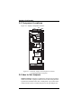
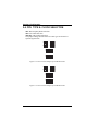
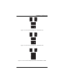
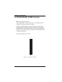
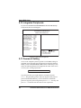
Hardware Configuration 2-2 Component Locations Figure 2-1 displays component locations. VGA COM 1 JP7 KBL JP6 EXKB Flash Disk SIO JP11 Real Time Clock JP12 JP14 Panel SPK USB IDE 2 IDE 1 PC-104 VRAM Flash BIOS GND HDL JP10 JP13 FDD KB BIOS VRAM PRT COM 2 PWR RST KB/ Mouse Chipset JP4 JP 9 JP2 JP 3 6xx86 CPU JP 8 JP1 Chipset SIMM 1 SIMM 2 SIMM 3 SIMM 4 Figure 2-1: Connector, Jumper and Component Locations on the Single-Board Computer 2-3 How to Set Jumpers Jumpers and Caps. Your PC is configured by the positions of jumpers on the circuit board. A jumper consists of two or more metal pins with a plastic base mounted on the card. A small plastic cap(with a metal contact inside) is used to connect the pins. For two-pin jumpers, the 12 CommPlete 4000 Server SBC, Model IPC-551