1
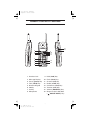
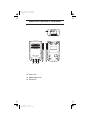
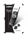
Color profile: Disabled Composite Default screen One Year Limited Warranty WARRANTOR: UNIDEN AMERICA CORPORATION (“Uniden”) ELEMENTS OF WARRANTY: Uniden warrants, for one year, to the original retail owner, this Uniden Product to be free from defects in materials and craftsmanship with only the limitations or exclusions set out below. WARRANTY DURATION: This warranty to the original user shall terminate and be of no further effect 12 months after the date of original retail sale. The warranty is invalid if the Product is (A) damaged or not maintained as reasonable or necessary, (B) modified, altered, or used as part of any conversion kits, subassemblies, or any configurations not sold by Uniden, (C) improperly installed, (D) serviced or repaired by someone other than an authorized Uniden service center for a defect or malfunction covered by this warranty, (E) used in any conjunction with equipment or parts or as part of any system not manufactured by Uniden, or (F) installed or programmed by anyone other than as detailed by the Operating Guide for this product. STATEMENT OF REMEDY: In the event that the product does not conform to this warranty at any time while this warranty is in effect, warrantor will repair the defect and return it to you without charge for parts, service, or any other cost (except shipping and handling) incurred by warrantor or its representatives in connection with the performance of this warranty. THE LIMITED WARRANTY SET FORTH ABOVE IS THE SOLE AND ENTIRE WARRANTY PERTAINING TO THE PRODUCT AND IS IN LIEU OF AND EXCLUDES ALL OTHER WARRANTIES OF ANY NATURE WHATSOEVER, WHETHER EXPRESS, IMPLIED OR ARISING BY OPERATION OF LAW, INCLUDING, BUT NOT LIMITED TO ANY IMPLIED WARRANTIES OF MERCHANTABILITY OR FITNESS FOR A PARTICULAR PURPOSE. THIS WARRANTY DOES NOT COVER OR PROVIDE FOR THE REIMBURSEMENT OR PAYMENT OF INCIDENTAL OR CONSEQUENTIAL DAMAGES. Some states do not allow this exclusion or limitation of incidental or consequential damages so the above limitation or exclusion may not apply to you. LEGAL REMEDIES: This warranty gives you specific legal rights, and you may also have other rights which vary from state to state. This warranty is void outside the United States of America. PROCEDURE FOR OBTAINING PERFORMANCE OF WARRANTY: If, after following the instructions in this Operating Guide you are certain that the Product is defective, pack the Product carefully (preferably in its original packaging). Include evidence of original purchase and a note describing the defect that has caused you to return it, The Product should be shipped freight prepaid by traceable means, or delivered, to warrantor at: Uniden America Corporation BCS-Repair 4700 Amon Carter Blvd. Fort Worth, TX 76155 800-235-3874, 8 a.m. to 5 p.m. Central, Monday through Friday 2 Y:...ANA9320 om.vp Tue Dec 03 15:21:07 2002 Color profile: Disabled Composite Default screen PRECAUTIONS Before you read anything else, please observe the following: WARNING! Uniden America Corporation DOES NOT represent this unit to be waterproof. To reduce the risk of fire, electrical shock, or damage to the unit, DO NOT expose this unit to rain or moisture. Precautions! Before you read anything else, please observe the following: Rechargeable Nickel-Metal-Hydride Battery Warning n n n n This equipment contains a Rechargeable NickelMetal-Hydride battery. The rechargeable Nickel-Metal-Hydride battery contained in this equipment may explode if disposed of in a fire. Do not short-circuit the battery. Do not charge the Rechargeable Nickel-MetalHydride battery used in this equipment in any charger other than the one designed to charge this battery as specified in the owner’s manual. Using another charger may damage the battery, or cause the battery to explode. Rechargeable Nickel-MetalHydride Batteries Must Be Disposed of Properly Ni-MH 5 Y:...ANA9320 om.vp Tue Dec 03 15:21:13 2002 Color profile: Disabled Composite Default screen Handset Controls & Functions 1 2 9 10 11 12 3 4 15 16 5 6 7 13 14 8 1. 2. 3. 4. 5. 6. 7. 8. Headset Jack Message Display Pause (pause) Key Talk (TALK) Key Numeric Keypad L2 Key L1 Key Microphone 9. 10. 11. 12. 13. 14. 15. 16. 6 Y:...ANA9320 om.vp Tue Dec 03 15:21:22 2002 Hold (hold) Key Flash (flash) Key Channel (CH) Key Redial (redial) Key Conference (conf) Key Transfer (xfer) Key Volume (RING/VOL) Key Ringer On/Off & Mic Mute ( ON/OFF MUTE ) Key Color profile: Disabled Composite Default screen Base Unit Controls & Functions 18 19 20 18. line 1 LED 19. power/status LED 20. line 2 LED 7 Y:...ANA9320 om.vp Tue Dec 03 15:21:27 2002 Color profile: Disabled Composite Default screen TABLE OF CONTENTS Important Safety Instructions . . . . . . . . . . . . . . . . . . . . . . . . . . . . . . . . . . . . . . . . . . . . . . . 2 About Your ANA 9320 . . . . . . . . . . . . . . . . . . . . . . . . . . . . . . . . . . . . . . . . . . . . . . . . . . . . . 4 Important Electrical Considerations . . . . . . . . . . . . . . . . . . . . . . . . . . . . . . . . . . . . . . . . . 5 Range . . . . . . . . . . . . . . . . . . . . . . . . . . . . . . . . . . . . . . . . . . . . . . . . . . . . . . . . . . . . . . . 5 Telephone Line Problems . . . . . . . . . . . . . . . . . . . . . . . . . . . . . . . . . . . . . . . . . . . . . . . . 5 Radio Interference . . . . . . . . . . . . . . . . . . . . . . . . . . . . . . . . . . . . . . . . . . . . . . . . . . . . . . 6 More Than One Cordless Telephone . . . . . . . . . . . . . . . . . . . . . . . . . . . . . . . . . . . . . . . 6 Privacy . . . . . . . . . . . . . . . . . . . . . . . . . . . . . . . . . . . . . . . . . . . . . . . . . . . . . . . . . . . . . . . 6 ANA 9320 Features . . . . . . . . . . . . . . . . . . . . . . . . . . . . . . . . . . . . . . . . . . . . . . . . . . . . . . . 7 Installing Your ANA 9320 . . . . . . . . . . . . . . . . . . . . . . . . . . . . . . . . . . . . . . . . . . . . . . . . . . 8 Selecting the Installation Location . . . . . . . . . . . . . . . . . . . . . . . . . . . . . . . . . . . . . . . . . . 8 Connecting the Telephone Line. . . . . . . . . . . . . . . . . . . . . . . . . . . . . . . . . . . . . . . . . . . . 8 Connecting the Telephone Cords . . . . . . . . . . . . . . . . . . . . . . . . . . . . . . . . . . . . . . . . . . 9 Applying Power to the Base and Charger Units . . . . . . . . . . . . . . . . . . . . . . . . . . . . . . 10 Wall Installation . . . . . . . . . . . . . . . . . . . . . . . . . . . . . . . . . . . . . . . . . . . . . . . . . . . . . . . 11 Attaching the Belt Clip to the Handset . . . . . . . . . . . . . . . . . . . . . . . . . . . . . . . . . . . . . . 16 Installing the Handset Battery Pack. . . . . . . . . . . . . . . . . . . . . . . . . . . . . . . . . . . . . . . . 17 Charging the Handset Battery Pack . . . . . . . . . . . . . . . . . . . . . . . . . . . . . . . . . . . . . . . 18 Low Battery Indicator . . . . . . . . . . . . . . . . . . . . . . . . . . . . . . . . . . . . . . . . . . . . . . . . . . . 18 Cleaning Charging Unit Contacts . . . . . . . . . . . . . . . . . . . . . . . . . . . . . . . . . . . . . . . . . 18 Using Your ANA 9320 Handset . . . . . . . . . . . . . . . . . . . . . . . . . . . . . . . . . . . . . . . . . . . . 19 ANA 9320 Handset Controls . . . . . . . . . . . . . . . . . . . . . . . . . . . . . . . . . . . . . . . . . . . . . 19 Earpiece Volume . . . . . . . . . . . . . . . . . . . . . . . . . . . . . . . . . . . . . . . . . . . . . . . . . . . . . . 20 Handset Ringer Tone and Volume . . . . . . . . . . . . . . . . . . . . . . . . . . . . . . . . . . . . . . . . 21 Vibrate Mode . . . . . . . . . . . . . . . . . . . . . . . . . . . . . . . . . . . . . . . . . . . . . . . . . . . . . . . . . 21 Handset Ringer Mute. . . . . . . . . . . . . . . . . . . . . . . . . . . . . . . . . . . . . . . . . . . . . . . . . . . 21 Using the Handset . . . . . . . . . . . . . . . . . . . . . . . . . . . . . . . . . . . . . . . . . . . . . . . . . . . . . 22 Answering a Call . . . . . . . . . . . . . . . . . . . . . . . . . . . . . . . . . . . . . . . . . . . . . . . . . . . . . . 23 Making a Call . . . . . . . . . . . . . . . . . . . . . . . . . . . . . . . . . . . . . . . . . . . . . . . . . . . . . . . . . 23 Redial Function . . . . . . . . . . . . . . . . . . . . . . . . . . . . . . . . . . . . . . . . . . . . . . . . . . . . . . . 23 Programming Functions . . . . . . . . . . . . . . . . . . . . . . . . . . . . . . . . . . . . . . . . . . . . . . . . . . 24 PBX or PSTN. . . . . . . . . . . . . . . . . . . . . . . . . . . . . . . . . . . . . . . . . . . . . . . . . . . . . . . . . 24 Program Mode Setup. . . . . . . . . . . . . . . . . . . . . . . . . . . . . . . . . . . . . . . . . . . . . . . . . . . 24 Programming Xfer in PBX . . . . . . . . . . . . . . . . . . . . . . . . . . . . . . . . . . . . . . . . . . . . . . . 25 Programming Conf in PBX. . . . . . . . . . . . . . . . . . . . . . . . . . . . . . . . . . . . . . . . . . . . . . . 26 Feature Buttons . . . . . . . . . . . . . . . . . . . . . . . . . . . . . . . . . . . . . . . . . . . . . . . . . . . . . . . 27 PBX Features . . . . . . . . . . . . . . . . . . . . . . . . . . . . . . . . . . . . . . . . . . . . . . . . . . . . . . . . 28 PSTN Features . . . . . . . . . . . . . . . . . . . . . . . . . . . . . . . . . . . . . . . . . . . . . . . . . . . . . . . 29 Optional Headset (EXP9730/9530) . . . . . . . . . . . . . . . . . . . . . . . . . . . . . . . . . . . . . . . . . . 31 Optional Accessories and Replacement Parts . . . . . . . . . . . . . . . . . . . . . . . . . . . . . . . . 32 Troubleshooting. . . . . . . . . . . . . . . . . . . . . . . . . . . . . . . . . . . . . . . . . . . . . . . . . . . . . . . . . 33 Specifications. . . . . . . . . . . . . . . . . . . . . . . . . . . . . . . . . . . . . . . . . . . . . . . . . . . . . . . . . . . 34 Uniden® is a registered trademark of Uniden America Corporation. AutoStandby™ and AutoTalk™ are trademarks of Uniden America Corporation. AutoStandby is a patented invention of Uniden America Corporation. 1 9 Y:...ANA9320 om.vp Tue Dec 03 15:21:31 2002 Color profile: Disabled Composite Default screen Important Safety Instructions When using your telephone equipment, basic safety precautions should always be followed to reduce the risk of fire, electrical shock, and injury to persons, including the following: 1. Read and understand all instructions. 2. Follow all warnings and instructions marked on the product. 3. Unplug this product from the wall outlet before cleaning. Do not use liquid cleaners or aerosol cleaners. Use a dry cloth for cleaning. 4. Do not use this product near water; for example, near a sink or in a wet area. 5. Do not place this product on an unstable cart, stand, or table. The telephone may fall, causing serious damage to the unit. 6. To protect the product from overheating, do not block or cover any slots or openings in the base Unit. This product should never be placed near or over a radiator or heat register. This product should not be placed in a built-in installation unless proper ventilation is provided. 7. This product should be operated only from the type of power source indicated on the marking label. 8. Do not allow anything to rest on the power cord. Do not locate this product where the cord will be damaged by persons walking on it. 9. Do not overload wall outlets and extension cords, as this can result in the risk of fire or electrical shock. 10. Never push objects of any kind into this product through the Base Unit slots, as they may touch dangerous voltage points or short out parts that could result in a risk of fire or electric shock. Never spill liquid of any kind on the product. 11. To reduce the risk of electric shock, do not disassemble this product. Contact qualified service personnel when some service or repair work is required. Opening or removing covers may expose you to dangerous voltages or other risks. Incorrect reassembly can cause electric shock when the appliance is subsequently used. 12. Unplug this product from the wall outlet and refer servicing to qualified service personnel under the following conditions: A. When the power supply cord is damaged or frayed. B. If liquid has been spilled into the product. C. If the product has been exposed to rain or water. 2 10 Y:...ANA9320 om.vp Tue Dec 03 15:21:31 2002 Color profile: Disabled Composite Default screen D. If the product does not operate normally when following the operating instructions. Adjust only those controls that are covered by the operating instructions. Improper adjustment of other controls may result in damage, and will often require extensive work by a qualified technician to restore the product to normal operation. E. If the product has been dropped, or the cabinet has been damaged. F. If the product exhibits a distinct change in performance. 13. Do not use the telephone to report a gas leak in the vicinity of the leak. CAUTION: To reduce the risk of fire or injury to persons by the battery, read and follow these instructions: 1. Use only the appropriate type and size Battery Pack specified in this Operating Guide. 2. Do not dispose of the Battery Pack in a fire. The cell may explode. 3. Do not open or mutilate the Battery Pack. Released electrolyte is corrosive and may cause damage to the eyes or skin. It may be toxic if swallowed. 4. Exercise care in handling the battery in order not to short the battery with conducting materials such as rings, bracelets, and keys. The battery or conductor may overheat and cause burns. 5. Charge the Battery Pack provided with or identified for use with this product only in accordance with the instructions and limitations specified in the instruction manual provided for this product. 6. Observe proper polarity orientation between the Battery Pack and battery charger. SAVE THESE INSTRUCTIONS 3 11 Y:...ANA9320 om.vp Tue Dec 03 15:21:31 2002 Color profile: Disabled Composite Default screen About Your ANA 9320 Congratulations on your purchase of the Uniden ANA 9320 Cordless Telephone. The ANA 9320 is designed and engineered to exacting standards for reliability, long life, and outstanding performance. It is designed to work with a PBX system. To get the most from your ANA 9320, please read this Operating Guide thoroughly. To help familiarize you with the features of your cordless phone, refer to the Handset illustration foldout from the front cover, and the Base Unit illustration foldout from the rear cover. Your ANA 9320 includes the following items: Base Unit Handset Telephone Cords 2 AC Adapters Rechargeable Battery (BT930) Belt Clip (EXP9302) Charging Unit Operating Guide (OM9320) Wall Plate Adapter Charging Unit Wall Mount (EXP9360) If any of these items are missing or damaged, contact your PBX Administrator. If your ANA 9320 is not performing to your expectations, please try the simple steps listed in the Trouble shooting section of this Guide. If you are still unable to resolve the problem, contact your PBX Administrator. 4 12 Y:...ANA9320 om.vp Tue Dec 03 15:22:09 2002 Color profile: Disabled Composite Default screen Important Electrical Considerations Warning: Please do not attempt to unplug any appliance during an electrical storm. Unplug all electrical appliances when you know an electrical storm is approaching. Lightning can pass through your household wiring and damage any device connected to it. This phone is no exception. Caution: Changes or modifications to this product not expressly approved by Uniden, or operation of this product in any way other than as detailed by this Operating Guide, could void your authority to operate this product. Range Your new phone is designed to achieve the maximum possible range by transmitting and receiving according to the highest specifications set forth by the FCC and IC. We have rated this phone to operate at a maximum distance with the qualification that the range depends upon the environment in which the telephone is used. Many factors limit range, and it would be impossible to include all the variables in our rating. The Maximum Range rating of this phone is meant to be used as a means of comparison against other range claims. Telephone Line Problems The FCC and IC have granted the telephone company the right to disconnect service in the event that your phone causes problems on the telephone line. Also, the telephone company may make changes in facilities and services which may affect the operation of your unit. However, your telephone company must give adequate notice in writing prior to such actions to allow you time for making necessary arrangements to continue uninterrupted service. If you are having trouble with your telephone service, you must first disconnect your phone to determine if it is the cause of your problem. If you determine that it is the cause, you must leave it disconnected until the trouble has been corrected. 5 13 Y:...ANA9320 om.vp Tue Dec 03 15:22:09 2002 Color profile: Disabled Composite Default screen Radio Interference Radio interference may occasionally cause buzzing and humming in your cordless Handset, or clicking noises in the Base Unit. This interference is caused by external sources such as a TV, refrigerator, vacuum cleaner, fluorescent lighting, computer equipment, or electrical storm. Your unit is NOT DEFECTIVE. If these noises continue and are too distracting, please check around your office to see what appliances may be causing the problem. In addition, we recommend that the Base not be plugged into a circuit that also powers a major appliance because of the potential for interference. Be certain that the antenna on the unit is fully extended when needed. In the unlikely event that you consistently hear other voices or distracting transmissions on your phone, you may be receiving radio signals from another cordless telephone or other source of interference. If you cannot eliminate this type of interference, you need to change to a different channel. Finally, it should be noted that some cordless telephones operate at frequencies that may cause interference to nearby TVs and VCRs. To minimize or prevent such interference, the base of the cordless telephone should not be placed near or on top of a TV or VCR. If interference is experienced, moving the cordless telephone farther away from the TV or VCR will often reduce or eliminate the interference. More Than One Cordless Telephone If you want to use more than one cordless telephone in your office, they must operate on different channels. Press the channel key to select a channel that provides the clearest communication. Privacy Note: Cordless phones are radio devices. Communications between the Handset and Base Unit of your cordless telephone are accomplished by means of radio waves which are broadcast over the open airways. Because of the inherent physical properties of radio waves, your communications can be received by radio receiving devices other than your own cordless telephone unit. Consequently, any communications using your cordless telephone may not be private. 6 14 Y:...ANA9320 om.vp Tue Dec 03 15:22:09 2002 Color profile: Disabled Composite Default screen ANA 9320 Features n n n n n n n n n n n n n n n n n Long Range 900MHz Digital 2-line, 16-digit LCD Display Ringer Volume Control Handset Volume Control Single button access to: CONFERENCE, HOLD, and TRANSFER features Four Function Keys: PAUSE, HOLD FLASH REDIAL 30 Simultaneous Conversations Separate Charging Stand AutoStandby AutoTalk Vibrator Ringer Alert Easy Installation Out of Range Protection Low Battery Protection System Wall Mountable separate Base Unit Wall Mountable separate Charging Unit Headset Jack (2.5mm) 7 15 Y:...ANA9320 om.vp Tue Dec 03 15:22:09 2002 Color profile: Disabled Composite Default screen Installing Your ANA 9320 Selecting the Installation Location Select a location for the ANA 9320 to avoid excessive heat or humidity. The Base Unit of your ANA 9320 can be placed on a desk or tabletop near a standard 120V AC outlet and telephone line jack. The Base Unit can also be mounted on a standard wall plate using the included Wall Mount Adapter. Keep the Base Unit and Handset away from sources of electrical noise (motors, fluorescent lighting, computers). Connecting the Telephone Line There are three types of phone outlets: 1) Modular Jack Plug the telephone line cord from the Base Unit into a standard modular telephone jack(s). (Note: If you do not have a modular jack, contact your local telephone company for information on the installation of these jacks.) 2) 4-Prong Jack An adapter (not included) is required. The adapter plugs into the 4-prong jack and the telephone line cord plugs into the adapter. 3) Hardwired Jack A modular jack converter (not included) is required. You may need to rewire when connecting the converter (making colorcoded connections). Note: Your Uniden Telephone Dealer or a telephone supply store can advise you on the proper adapter or converter. 8 16 Y:...ANA9320 om.vp Tue Dec 03 15:22:10 2002 Color profile: Disabled Composite Default screen Connecting the Telephone Cords The ANA 9320 must be connected to a PSTN or an analog PBX port telephone line. TIP: To setup PSTN or PBX, refer to page 24. CAUTION: n Never install telephone wiring during a lightning storm. n Never touch uninsulated telephone wires or terminals unless the telephone line has been disconnected at the network interface. n Use caution when installing or modifying telephone lines. ] Single Cord, 2-line Combined Telephone Cord Installation ] Two Cord, Two-Line Telephone Cord Installation 9 17 Y:...ANA9320 om.vp Tue Dec 03 15:22:16 2002 Color profile: Disabled Composite Default screen Applying Power to the Base and Charger Units Use only the supplied AC Adapter: EXP9704 IMPORTANT! Route the power cord where it will not create a trip hazard, or where it could become chafed and create a fire or other electrical hazards. Note: If you cannot plug the AC Adapter into the outlet, contact someone about replacing the outlet. The unique design of your ANA 9320 allows you to place the Handset in the Charging Unit with or without the Belt Clip attached. Use only the supplied AC Adapter: AD-970. 10 18 Y:...ANA9320 om.vp Tue Dec 03 15:22:30 2002 Color profile: Disabled Composite Default screen Wall Installation Standard Wall Plate Mounting These Phones are designed to be mounted on a standard wall plate. To attach the wall mount stand to the Base Unit: 1. Slide the Wall Mount stand into the notches at the top of the Base Unit, push the Wall Mount stand down and snap it into place. 2. Plug the AC Adapter into the Base Unit as previously described. 3. Place the AC Adapter cord inside the molded channel of the Wall Mount stand. 4. Plug one end of the short telephone cord into the LINE jack on the Base Unit. Optionally, plug one end of a standard 2500 type desk phone into the PHONE jack. Then place the telephone cord(s) inside the molded channel(s) on the bottom of the Wall Mount stand. 5. Plug the other end of the short telephone cord into the modular wall jack. 11 19 Y:...ANA9320 om.vp Tue Dec 03 15:22:37 2002 Color profile: Disabled Composite Default screen 6. Place the Base Unit on the posts of the wall plate and push down until it’s firmly seated. 7. Plug the AC Adapter into a standard 120V AC wall outlet. Note: Do not use an outlet controlled by a wall switch. Direct Wall Mounting If you do not have a standard wall plate, you can mount your phone directly on a wall. Before mounting your phone, consider the following: n Select a location away from electrical cables, pipes, or other items behind the mounting location that could cause a hazard when inserting screws into the wall. n Make sure the wall material is capable of supporting the weight of the Base Unit. n Use #10 screws with anchoring devices suitable for the wall material where the Base Unit will be placed. 12 20 Y:...UC790B_2(ANA9320) OM.vp Wed Dec 04 11:52:21 2002 Color profile: Disabled Composite Default screen 1. Insert two mounting screws 3 15/16 inches apart. Allow about 3/16 of an inch between the wall and screw heads for mounting the phone. 2. Plug and secure the AC Adapter cord by following steps 2 and 3 of the Standard Wall Plate Mounting. 3. Plug one end of the telephone line cord into the LINE jack on the Base Unit. Optionally, plug one end of a standard 2500 type desk phone into the PHONE jack. Then place the telephone cord(s) inside the molded channel(s) on the bottom of the Wall Mount stand. 4. Place the Base Unit on the posts of the wall screws and push down until it’s firmly seated. 5. Plug the other end of the short telephone cord into a telephone wall jack. 6. Plug the AC Adapter into a standard 120V AC wall outlet by following step 7 of the Standard Wall Plate Mounting. 13 21 Y:...ANA9320 om.vp Tue Dec 03 15:22:58 2002 Color profile: Disabled Composite Default screen Charging Unit Wall Mounting The Charging Unit is also designed to be wall mounted. Before mounting your charging unit, consider the following: n Select a location away from electrical cables, pipes, or other items behind the mounting location that could cause a hazard when inserting screws into the wall. n Make sure the wall material is capable of supporting the weight of the Charging Unit. n Use #10 screws with anchoring devices suitable for the wall material where the Charging Unit will be placed. 1. Insert two mounting screws 1-1/5 inches apart. Allow about 3/16 of an inch between the wall and screw heads for mounting the phone. 2. Pass the one end through the hole of the wall mount stand and plug it into the Charging Unit. Wrap the AC Adapter cord around the strain relief. 14 22 Y:...ANA9320 om.vp Tue Dec 03 15:23:03 2002 Color profile: Disabled Composite Default screen 3. Slide the wall mount stand into the notches on the bottom of the charging unit. 4. Place the Charging Unit on the posts of the wall screws and push down until it’s firmly seated. 5. Plug the AC Adapter into a standard 120V AC wall outlet. 15 23 Y:...ANA9320 om.vp Tue Dec 03 15:23:11 2002 Color profile: Disabled Composite Default screen Attaching the Belt Clip to the Handset You can use the Belt Clip to attach the Handset to your belt or pocket for convenient portability. 1. Snap the tab out of the Belt Clip notch on the top of the Handset. 2. Slide the clip into the tab slot. (CAUTION: The Belt Clip is designed to fit snugly onto the Handset.) 3. Press firmly until it snaps into place. 4. To remove, simply press the retain clip in toward the Belt Clip blade and slide the clip up at the same time. 16 24 Y:...ANA9320 om.vp Tue Dec 03 15:23:20 2002 Color profile: Disabled Composite Default screen Installing the Handset Battery Pack 1. Remove the battery cover by pressing the latch and sliding the cover down and off of the Handset. 2. Connect the battery pack connector observing correct polarity to the jack inside the battery compartment. Do not exert any force on this connection. It could cause damage to the battery or handset. Once you are certain that you have made a good connection, then insert the battery pack into the battery compartment. Do not pinch the wires. 3. Place the cover and slide the cover up until it latches into the Handset. 17 25 Y:...ANA9320 om.vp Tue Dec 03 15:23:30 2002 Color profile: Disabled Composite Default screen Charging the Handset Battery Pack The Rechargeable Ni-MH Battery Pack must be fully charged before using your ANA 9320 for the first time. (Note: Charge the Battery Pack without interruption for 5 hours.) 1. Place the Handset into the Charging Unit. 2. Make sure the CHARGE indicator illuminates. If the CHARGE light doesn’t illuminate, check to see that the AC Adapter is plugged in, and that the Handset is making good contact with the Charging Unit charging contacts. Low Battery Indicator When the Battery Pack in the Handset is low and needs to be charged, you will see a message on the display. On a Call In Standby Mode All keys and functions are available. None of the buttons operate. Handset beeps once every 3 seconds Handset beeps every 15 seconds for 3 minutes. Complete your call as quickly as possible Cannot make call nor receive a call. Replace Battery pack within 20 seconds to continue call. Replace Battery Pack before making a call. Return the Handset to the Charging Unit for charging. Cleaning Charging Unit Contacts To maintain a good charge, it is important to clean all charging contacts on the Handset, and Charging Unit about once a month. Use a pencil eraser or other contact cleaner. Do not use any liquids or solvents. 18 26 Y:...ANA9320 om.vp Tue Dec 03 15:23:41 2002 Color profile: Disabled Composite Default screen Using Your ANA 9320 Handset Before using your ANA 9320, be sure to raise the antenna to the vertical position. Note: Operation of the ANA 9320 is performed using the Handset out of the Charging Unit. ANA 9320 Handset Controls 19 27 Y:...ANA9320 om.vp Tue Dec 03 15:23:49 2002 Color profile: Disabled Composite Default screen Earpiece Volume Press RING/VOL on the side of the Handset during a call to select the earpiece volume of the handset. 20 28 Y:...ANA9320 om.vp Tue Dec 03 15:23:52 2002 Color profile: Disabled Composite Default screen Handset Ringer Tone and Volume Pressing RING/VOL on the side of the Handset in standby mode to select seven ringer tones and volume combinations. Vibrate Mode “Ring off” shown on the above display is the Vibrate Mode. If you set the ringer off and the Handset is not on the charger, the Handset will vibrate when there is an incoming call. If you set the ringer off and the Handset is on the charger, the Handset will ring as Ring Type-A Low. Handset Ringer Mute You can temporarily mute the handset ringer tone. In standby mode, press and hold the ON/OFF MUTE key on the side of the handset for 2 seconds. You will see the ring off icon. If you press and hold the key for 2 seconds again also in standby mode, the ring off icon will disappear. 21 29 Y:...ANA9320 om.vp Tue Dec 03 15:24:01 2002 Color profile: Disabled Composite Default screen Using the Handset When you pick up the Handset and press TALK, you will see: After the connection has been made between the Handset and Base, the display will show the lines currently connected: Or, you may see one of the following: Condition No Connection to Base Unit Indicator LCD Screen Error Tone Channel busy Error tone No display indication Line in use L1 or L2 Indicator blinks. L1 line in use or L2 line in use If the Handset is at the range limit of the ANA 9320, or no power is going to the Base Unit, you may see: Take the following action: During a Call Sound is Muted. Condition Action Move back in range within Move back within range or 20 seconds or check check power to the base. power to the base. 22 30 Y:...ANA9320 om.vp Tue Dec 03 15:24:14 2002 In Standby Mode Can’t make or answer calls (Phone may ring intermittently). Color profile: Disabled Composite Default screen Answering a Call When you receive a call, the Handset rings and you’ll see: Handset in the Charging Unit Pick up the Handset. The AutoTalk feature allows you to answer the call immediately. Handset out of Charging Unit Press TALK. Or press any key on the numeric keypad, hold, pause, flash, conf, or xfer. L1 can be used only when the call is on Line 1. L2 with the call on Line 2. When you finish the call, place the Handset back in the Charging Unit. AutoStandby automatically hangs up the phone. — OR — Press TALK to hang up the phone Making a Call Press TALK. (The ANA 9320 selects the last line used. If one line is busy, the phone automatically selects an available line.) OR Press L1 or L2. When you hear a dial tone, enter the number you are calling. To hang up, press TALK. Redial Function The ANA 9320 stores the last phone number you dialed. To redial the number: Press TALK then redial. The phone will redial the last number called. 23 31 Y:...ANA9320 om.vp Tue Dec 03 15:24:22 2002 Color profile: Disabled Composite Default screen Programming Functions PBX or PSTN In the Programming mode, you can select either Analog PBX or PSTN (Public Service Telephone Network) operation. The default is PSTN. Available features of each mode of operation are illustrated in the table below. Feature Conference Transfer Analog PBX PSTN Conference by PBX Connect Lines 1 & 2 Transfer by PBX Not Available Note: Both Conference and Transfer commands must be programmed to their respective keys before these features can be used. * This note is for PBX mode. Program Mode Setup To enter the Program mode, perform the following steps: 1. In standby mode, press and hold and #. While holding them, press and hold TALK until a short beep is heard and the handset LCD displays: ON/OFF MUTE or 0 to switch between 2. Press RING/VOL, PSTN and Analog PBX modes. 3. Press TALK to enter your selection into memory. The handset LCD displays: The phone returns to standby mode. For operation in PSTN mode, see page 29. For operation in PBX mode, see page 28. 24 32 Y:...UC790B_2(ANA9320) OM.vp Wed Dec 04 11:52:29 2002 Color profile: Disabled Composite Default screen Programming Xfer in PBX Note: Before programming these commands, contact your PBX Administrator to obtain programming codes. The xfer key can be programmed for special use, such as causing a "Hook Flash" followed by a special number or function. The Hook Flash is used to send a signal to the PBX system to initiate a transfer. For example - to program xfer for "Hook Flash" and 9 for outside transfers only: Press and hold pause for two seconds. The talk icon blinks. Press flash. Press 9. Press xfer. Press xfer. For the ANA 9320, the transfer key is operated by the Hook-Flash function. Program your system transfer code with the assistance of the PBX System Administrator. 25 33 Y:...UC790B_2(ANA9320) OM.vp Tue Dec 03 18:41:06 2002 Color profile: Disabled Composite Default screen Programming Conf in PBX Your PBX system's configuration determines how the conference feature works. Contact your PBX Administrator for exact operation details. The example below is just a representation. For example - to program the conf key for "Hook Flash" and "9": Press and hold pause for two seconds. The “TALK” icon blinks. Press flash. Press 9. Press conf. Press conf. For the ANA 9320, the conference key is operated by the Hook-Flash function. Program your system conference code with the assistance of the PBX Administrator. Note: The conference key can be programmed for special use, such as causing a "Hook Flash" followed by a special number of function. 26 34 Y:...ANA9320 om.vp Tue Dec 03 15:24:55 2002 Color profile: Disabled Composite Default screen Feature Buttons Note: The exact operation of the Feature Buttons depends on how your PBX system is configured. Contact your PBX Administrator for more information. : Placing a call “on hold” Press hold. You will see the following display: To resume the call, press L1, L2 or TALK. : Transferring a Call The xfer key must be programmed before use. Refer to “Programming Xfer in PBX” section on page 25. Press xfer (TRANSFER). You will see the following display: Dial the target number. When the receiving party answers, press xfer to complete the transfer. Note: The transfer feature is not available in PSTN mode. : Connecting a Conference Call To connect a second party to a call in progress, press conf (CONFERENCE). You will see the following display: Dial the second party’s number. When the other party answers, press conf to have a three-way conversation. Note: In PBX mode, multiline conferencing is available according to the configuration of the PBX system. 27 35 Y:...ANA9320 om.vp Tue Dec 03 15:25:12 2002 Color profile: Disabled Composite Default screen PBX Features L1 Key Press the L1 key to initiate a call on Line 1. L2 Key Press the L2 key to initiate a call on Line 2. conf Key In PBX mode, the conf (conference) key must first be programmed. Refer to the section entitled "Programming Conf in PBX". xfer Key Press xfer (transfer). Dial the target number. When the receiving party answers, press xfer to complete the call. Note: This feature is only available in PBX mode. hold Key Press once and the call is placed on hold. Press L1, L2 or TALK to resume the call. pause Key In PBX mode, the pause key is used to program the xfer and conf feature buttons. Refer to the sections entitled "Programming xfer in PBX" and "Programming Conf in PBX". flash Key Press once to cause a "Hook Flash" while on a call. In standby mode, you can redial any one of the last three numbers previously dialed. ON/OFF MUTE Key This key turns the handset MIC on or off while in TALK mode. It toggles between on and off. 28 36 Y:...ANA9320 om.vp Tue Dec 03 15:25:12 2002 Color profile: Disabled Composite Default screen RING/VOL Key This key selects the ringer volume level or tone (or silent alert) during standby mode, and handset earpiece audio level during a call. This key also selects an item during programming mode. CH Key The ANA 9320 automatically selects the clearest of three channels during a call for maximum audio quality. But, if you hear static or noise during a call, press CH to select a clear channel. PSTN Features L1 Key Press the L1 key to initiate a call on Line 1. L2 Key Press the L2 key to initiate a call on Line 2. conf Key To connect a call in progress with a second party: 1. Press hold to place the current call on hold. 2. Press L2. 3. Dial the number of a second party. 4. When the party answers, press conf to have a threeway conversation. 29 37 Y:...UC790B_2(ANA9320) OM.vp Tue Dec 03 18:41:14 2002 Color profile: Disabled Composite Default screen xfer Key Note: This feature is not available in PSTN mode. hold Key Press once and the call is placed on hold. Press L1, L2 or TALK to resume the call. pause Key Press once to cause a four second pause while dialing a number. flash Key Press once to cause a "Hook Flash" while on a call. In standby mode, you can redial any one of the last three numbers previously dialed. ON/OFF MUTE Key This key turns the handset MIC on or off while in TALK mode. It toggles between on and off. RING/VOL Key This key selects the ringer volume level or tone (or silent alert) during Standby mode, and handset earpiece audio level during a call. This key also selects an item during programming mode. CH Key The ANA 9320 automatically selects the clearest of three channels during a call for maximum audio quality. But, if you hear static or noise during a call, press CH to select a clear channel. 30 38 Y:...ANA9320 om.vp Tue Dec 03 15:25:23 2002 Color profile: Disabled Composite Default screen Optional Headset (EXP9730/EXP9530) The optional Headset provides a “Hands-Free” Option for the ANA 9320. With the Headset installed, you can use the Belt Clip to carry the Handset, and conduct a conversation using the Headset. To install the optional Headset, open the cover over the Headset Jack and plug the Headset in. No other settings are needed. Operation of the ANA 9320 using the Headset is exactly the same as that of without Headset. Only the difference is you will hear through the Headset earphone, and talk through the Headset microphone. The Handset earphone and microphone (mouthpiece) are disconnected. Note: EXP9530 can be used over the head or over the ear. 31 39 Y:...ANA9320 om.vp Tue Dec 03 15:25:28 2002 Color profile: Disabled Composite Default screen Optional Accessories and Replacement Parts For the following Optional Accessories and Replacement Parts contact your PBX Administrator. EXP9704 AC Adapter for Base Unit Telephone Cords Belt Clip EXP9302 750 mAh Battery BT-930 Operating Guide OM9320 Base Unit Wall Mount EXP9660 Headset EXP9530 Headset EXP9730 Charger EXP9785 AC Adapter AD-970 Charging Unit Wall Mount EXP9360 32 40 Y:...ANA9320 om.vp Tue Dec 03 15:25:58 2002 Color profile: Disabled Composite Default screen Troubleshooting If your ANA 9320 Cordless Telephone is not performing to your expectations, please try these simple steps. If you are still unable to resolve the problems, contact your PBX Administrator. Note: Do not attempt to service this unit yourself. All service must be done by qualified service personnel. Problem Charge light won’t illuminate when Handset is placed in Charging Unit. Suggestion • Make sure the AC Adapter is plugged into • • • Conversation interrupted frequently. Warning tone and NO SERVICE message. Handset doesn’t ring. • • • • • • • • • • the Charging Unit and wall outlet. Make sure Handset is properly seated in Charging Unit. Make sure the Battery Pack is properly placed in the Handset. Make sure that the charging contacts on the Handset and Charging Unit are clean. Make sure that the Base Unit antenna is fully vertical. Move closer to the Base Unit. Check for Low Battery warning. Move closer to the Base Unit. Make sure the AC Adapter is plugged into the Base Unit and wall outlet. The Battery Pack may be weak. Charge the Battery Pack for 5-6 hours. Make sure the Base Unit antenna is fully vertical. The Handset may be too far away from the Base Unit. The ringer maybe set to Off (see page 21). Make sure the AC Adapter is plugged into the Base Unit and wall outlet. 33 41 Y:...ANA9320 om.vp Tue Dec 03 15:25:58 2002 Color profile: Disabled Composite Default screen Specifications Frequency Control : Phase Lock Loop Modulation : FM Operating Temperature : 0° to 50° C (+32° F to +122° F) Base Unit Receive/Transmit Frequency : 902 MHz to 928 MHz Power Requirements : 10V DC from supplied AC Adapter Size : 4 1/4 in. W x 7 5/8 in. D x 2 1/4 in. H Weight : Approx. 15.6 oz. Handset Receive/Transmit Frequency : 902 MHz to 928 MHz Power Requirements : Ni-MH Battery Pack Size : 2 in. W x 1 1/4 in. D x 5 1/2 in. H without antenna Weight : Approx. 5.2 oz. with battery Battery : Capacity 750 mAH, 3.6 V Talk Time : 6 hours (typical) Standby Time : 5 days (typical) Specifications shown are typical and subject to change without notice. 34 42 Y:...ANA9320 om.vp Tue Dec 03 15:25:59 2002 Color profile: Disabled Composite Default screen MEMO 35 43 Y:...ANA9320 om.vp Tue Dec 03 15:25:59 2002