1
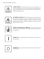
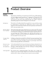
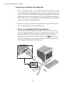
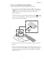
AutoView 424
Installer/User Guide
™
AV424
AV424R
AV416
AV416R
4991 Corporate Drive
Huntsville, Alabama 35805-6201 • USA
256-430-4000 (Fax) 256-430-4030
www.cybex.com
Supported by
TM
Technology Corporation
274 Madison Avenue, New York, NY 10016
Tel: 212-679-0050 • Fax: 212-679-0040
E-mail: Sales@RackitTechnolog y.com
www.RackitTechnology.com
AutoView 424 Installer/User Guide
™
AutoView 424
Installer/User Guide
Cybex Computer Products Corporation
4991 Corporate Drive
Huntsville, Alabama 35805-6201 • USA
(Tel) 256-430-4000 (Fax) 256-430-4030
www.cybex.com
©2000 Cybex Computer Products Corporation. All rights reserved.
IBM, ScrollPoint, PC/AT and PS/2 are registered trademarks of International Business Machines
Corporation. ScrollPoint is a trademark of International Business Machines Corporation. Expert Mouse is a
registered trademark of Kensington Technology Group. Microsoft and IntelliMouse are trademarks or
registered trademarks of Microsoft Corporation. Logitech and Kensington are registered trademarks of their
respective companies. MouseMan, Marble and TrackMan are registered trademarks of Logitech, Inc. Cybex
and the Cybex logo are registered trademarks of Cybex Computer Products Corporation. AutoView,
Commander, LongView, AutoBoot and all part numbers are trademarks of Cybex Computer Products
Corporation. IntelliMouse is a trademark of Microsoft Corporation.
AutoView 424 Installer/User Guide
FCC Notification
Warning: Changes or modifications to this unit not expressly approved by
the party responsible for compliance could void the user's authority to
operate the equipment.
Note: This equipment has been tested and found to comply with the limits
for a Class A digital device, pursuant to Part 15 of the FCC Rules. These
limits are designed to provide reasonable protection against harmful
interference when the equipment is operated in a commercial environment.
This equipment generates, uses and can radiate radio frequency energy
and, if not installed and used in accordance with the instruction manual,
may cause harmful interference to radio communications. Operation of
this equipment in a residential area is likely to cause harmful interference
in which case the user will be required to correct the interference at his
own expense.
Canadian Notification
This digital apparatus does not exceed the Class A limits for radio noise
emissions from digital apparatus set out in the Radio Interference
Regulations of the Canadian Department of Communications.
Le présent appareil numérique n'émet pas de bruits radioélectriques les
limites applicables aux appareils numériques de la class A prescrites dans
le Règlement sur le brouillage radioélectrique édicté par le Ministere des
Communications du Canada.
Table of Contents
Chapter 1 - Product Overview
Feature Overview ........................................................................................................................................................ 1
Compatibility ................................................................................................................................................................ 3
Chapter 2 - Installation
Basic Install ................................................................................................................................................................... 5
Advanced Install ...................................................................................................................................................... 11
Chapter 3 - Basic Operations
Overview ...................................................................................................................................................................... 13
Keyboard Control ..................................................................................................................................................... 14
Keyboard Switching ................................................................................................................................................ 15
System Control & Maintenance .......................................................................................................................... 16
Chapter 4 - On-Screen Display Operations
Activating OSD ......................................................................................................................................................... 17
The OSD Window ..................................................................................................................................................... 18
The Command Menu .............................................................................................................................................. 19
Basic Channel Maintenance ................................................................................................................................ 20
The ID Window ......................................................................................................................................................... 22
Administrator Functions ........................................................................................................................................ 24
Chapter 5 - Advanced Operation
Multiuser Operation ................................................................................................................................................ 27
Multi Chassis Operation ........................................................................................................................................ 28
Keyboard Translation ............................................................................................................................................. 30
Chapter 6 - Channel Scanning
Choosing a Scanning Method ............................................................................................................................. 33
Turning Scanning On and Off ............................................................................................................................. 34
Scanning by List ....................................................................................................................................................... 35
Chapter 7 - Appendices
A: AutoView Specifications .................................................................................................................................. 37
B: LongView Specifications .................................................................................................................................. 38
C: FLASH Upgrading ............................................................................................................................................... 39
D: Troubleshooting .................................................................................................................................................. 41
E: Problem Report .................................................................................................................................................... 45
AutoView 424 Installer/User Guide
INSTRUCTIONS: The exclamation point within an equilateral triangle is intended to alert the user to the presence of important operating and maintenance (servicing) instructions in the literature accompanying the appliance.
DANGEROUS VOLTAGE: The lightning flash with arrowhead symbol, within an equilateral triangle, is intended to alert the user to the
presence of uninsulated “dangerous voltage” within the product's
enclosure that may be of sufficient magnitude to constitute a risk of
electric shock to persons.
PROTECTIVE GROUNDING TERMINAL: A terminal which must be
connected to earth ground prior to making any other connections to
the equipment.
POWER ON: This symbol indicates the principal on/off switch is in
the on position.
POWER OFF: This symbol indicates the principal on/off switch is in
the off position.
1
Feature
Overview
Product Overview
The AutoView 424 allows you to control up to 256 PC, Sun or USB computers
with one keyboard, monitor and mouse. It supports Sun Workstations, USB
computers, IBM PC/AT and PS/2 systems and 100% compatible machines
with support for VGA, SVGA, XGA and XGA-II video. Sun and PS/2 keyboard
and mouse peripherals connect through the rear of the unit.
Multiplatform
The AutoView 424 adds multiplatform capabilities to your switching system
by simultaneously supporting any combination of PS/2, Sun or USB
computers in the same system. Switch easily across platforms with AutoView
424’s on-ocreen menu system.
Multiuser/Remote
Access Capability
The AutoView 424 supports two simultaneous users in the system. This second
user may be placed up to 500 feet away from the AutoView 424 system. Builtin extension lets you place your second keyboard, monitor and mouse wherever
you need them most. Within the base unit, AutoView 424 performs as a
complete 2 x 24 matrix switch with both users independently accessing any of
the 24 attached PCs at the same time.
On-screen display
capability
Configure and control your AutoView 424 with on-screen menuing. Name
your computer channels anything you wish, then select the desired computer
from an easy-to-use menu. Secondary menus let you configure and initiate
channel scanning and other system features.
Advanced security
for total control
over system access
Use the advanced multi-level security feature to configure and control server
access for every type of user in the system. The administrator has full access
privileges, while individual users can have viewing or viewing/editing
capability for each attached server.
FLASH Upgradable
The AutoView 424 is FLASH upgradable. This allows you to update your
firmware at any time through a simple serial connection to insure that your
AutoView 424 is always running the most current version available.
1
AutoView 424 Installer/User Guide
Mouse support
The AutoView 424 offers support for numerous PS/2 mice including: IBM
ScrollPoint, Logitech MouseMan Wheel, Logitech Trackman Marble Wheel,
Logitech Trackman Marble FX, Kensington 4 Button Mouse, Microsoft Explorer
Mouse and the Microsoft IntelliMouse family.
Plug and play
The AutoView 424 supports Plug and Play video and is compliant with the
VESA DDC2B standard.
Mouse
translation
For added compatibility with your current equipment, AutoView 424 features
mouse translation capability. Operated through the AutoView 424, your
mouse will work with any attached computer- regardless of whether the
computer is Sun, USB or PS/2 mouse compatible!
Expansion for up
to 64 computers
An AutoView 424 unit will support from one to 24 attached computers, or
channels, depending on the model. If more than 24 channels are needed,
multiple units can be cascaded together for expansion. An extra tier of units
can be connected for a total of 256 attached computers in one system.
“Keep Alive”
feature
AutoView 424’s “Keep Alive” feature allows attached servers to power the unit
in the event of an AutoView 424 power failure. This prevents attached
computers from locking up and keeps you from losing time and data.
OSD Configuration
Utility
The OSD Configuration Utility allows the administrator to easily configure
and download a channel list with defined users and access privileges to the
entire system. This utility will also read and save your current configuration
for extra security.
AutoBoot
technology
The AutoBoot feature boots all attached servers during initial power-up or
after a power failure. Computers are booted transparently without operator
intervention, and may be powered-up one-at-a-time or all at once. When the
power stabilizes, a channel may be selected.
Built-in scanning
capabilities
A built-in scanning feature allows you to automatically monitor, or scan,
connected computers without intervention. When keyboard activity is
detected, scanning is suspended until all activity stops. Scanning then
resumes with the next channel in sequence.
Keyboard switching
In addition to using the on-screen menus, you can also switch computer
channels with a simple keyboard sequence.
2
Product Overview
16-port version
The AutoView 424 is also available in a 16 port version known as the AutoView
416. Aside from the number of ports, all information in this manual that
applies to the AutoView 424 is also applicable to the AutoView 416.
A typical AutoView 424 configuration is shown below.
Compatibility
XGA/XGA-II
support
If you wish to use XGA or XGA-II video, you will need to purchase an adaptor
available through Cybex.
3
AutoView 424 Installer/User Guide
2
Installation
Basic Install
1. Power down all computers that will be part of your AutoView
424 system.
Connecting your Local Peripherals
2. Plug your VGA monitor cable into the port labeled on the back of your
AutoView 424. For SUN support plug your Sun connector into the port
labeled “SUN”, for PS/2 peripherals, plug your PS/2 keyboard cable and
your PS/2 mouse cable into the ports labeled
and respectively.
Note: A PS/2 keyboard will not function if a Sun keyboard is attached.
However, you may use a PS/2 mouse with a Sun keyboard.
PS/2 CONNECTIONS SHOWN
VGA MONITOR CABLE
PS/2 KEYBOARD CABLE
PS/2 MOUSE CABLE
5
AutoView 424 Installer/User Guide
Connecting your Remote Peripherals
3. Plug a standard Category 5 Unshielded Twisted Pair cable (up to 500
feet) into the RJ-45 style modular jack on the rear of the AutoView 424.
Cybex C5T or Cybex P5T cable is strongly recommended to achieve best
performance and maximum distance. If you use a different Category 5
cable, make sure it is terminated to the EIA (TIA) 568 B standard,
commonly used for 10BaseT Ethernet.
4. Route the Category 5 cable to the location where you intend to place
the secondary monitor, keyboard and mouse.
5. If you are using Remote PS/2 peripherals
Connect your monitor, keyboard and mouse to the connectors on the
rear of the LongView Receiver just as you would connect them to your
computer. Make sure you connect your monitor’s power supply to
appropriate electrical outlets. (Please note that the
connector on
the rear of the Receiver is not used in any AutoView 424 configuration.
Do not connect anything to this connector.)
6
Installation
If you are using Remote Sun peripherals
(This will require a VAK-1 adaptor kit available from Cybex)
If your monitor uses a 13W3 plug, connect the 15HDD male adapter to
the port of your LongView Receiver and your monitor cable to your
15HDD adaptor. Otherwise, plug your monitor directly into the
LongView Receiver.
Plug the ends of the 6-pin mini-DIN male adaptors into the
and
ports on your LongView Receiver and then plug the Sun keyboard/
mouse cable into the VAK-1 adaptor.
6. Connect the Categor y 5 cable to the modular jack on the rear of the
Receiver.
7. Connect the circular power plug from the wall mount power supply to
the power port on the LongView Receiver. Then plug the power supply
into a convenient electrical outlet. Verify that the Receiver’s POWER
indicator is now lit.
7
AutoView 424 Installer/User Guide
Cable
Description
Length
CIFCM-4
CIFCM-8
CIFCM-15
CIFCM-30
PS/2 only/VGA
PS/2 only/VGA
PS/2 only/VGA
PS/2 only/VGA
4 ft.
8 ft.
15 ft.
30 ft.
CUSBM-4
CUSBM-8
CUSBM-12
USB/VGA
USB/VGA
USB/VGA
4 ft.
8 ft.
12 ft.
CWSNM-4
CWSNM-8
CWSNM-15
CWSNM-30
SUN Kbd/Mouse 13W3
SUN Kbd/Mouse 13W3
SUN Kbd/Mouse 13W3
SUN Kbd/Mouse 13W3
4 ft.
8 ft.
15 ft.
30 ft.
CVSNM-4
CVSNM-8
CVSNM-15
CVSNM-30
SUN Kbd/Mouse VGA
SUN Kbd/Mouse VGA
SUN Kbd/Mouse VGA
SUN Kbd/Mouse VGA
4 ft.
8 ft.
15 ft.
30 ft.
8
Installation
Connecting Computers to the AutoView 424
8. Locate the input cable appropriate to the computer you are connecting.
(AutoView 424 cable types are identified on the previous page.) Plug this
cable into any numbered channel port on the rear of the AutoView 424.
The other end of the input cable will have up to three connectors depending
on type.
Plug these connectors into the matching ports on your computer.
PS/2 KEYBOARD CABLE
PS/2 MOUSE CABLE
VGA MONITOR CABLE
CIFCA CABLE SHOWN
9. Locate your next input cable. Repeat step 8 until all computers are
properly attached to the AutoView 424.
9
AutoView 424 Installer/User Guide
10. Locate the power cord that came with your AutoView 424 unit and plug it
into the IEC power connector on the AutoView 424. Make sure that the
power switch is off, then plug the other end of the power cord into an
appropriate AC wall outlet. This outlet must be near the equipment and
easily accessible to allow for unplugging prior to any servicing of the unit.
11. Power-up your AutoView 424 unit first, then power up all attached
computers.
12. If your remote location utilizes Sun peripherals, you will need to
configure the AutoView 424 to recognize them before they can be
used. To do this:
a. At the local user, activate the on-screen display (OSD) by
pressing either of the keyboard Control keys twice
within one second.
b. Press the Control key twice more to access Administrator Commands.
c. Use your arrow keys to highlight “Administrator Functions” and press Enter.
d. Highlight and select the “Remote User” menu selection.
Use the space bar to cycle through peripheral types and
select the ones appropriate to your system. Press Enter
to select.
The AutoView 424 and all attached computers should be
powered-down before servicing the unit. Always disconnect
the power cord from the wall outlet.
10
Installation
Advanced Install
Attaching Multiple AutoView 424 Units
(Please note that CIFCM cables are required for cascading.)
1. Follow steps 1-8 of the Basic Install section for each cascaded unit.
2. Plug the 25-pin “mini-D” connector of your CIFCM input cable into any
available channel port on the rear of your base AutoView 424 unit.
3. Plug the 15-pin video connector on the other end of the cable into the
port labeled on your first cascading AutoView 424 unit. Plug the
PS/2 mouse connector into the
port. Plug the remaining 6-pin
miniDIN keyboard connector into the
port.
4. Repeat steps 2-3 for every cascaded AutoView 424 unit in your system.
CASCADING
UNIT
BASE UNIT
PS/2 KEYBOARD CABLE
PS/2 MOUSE CABLE
VGA MONITOR CABLE
5. Follow steps 9-11 of the Basic Install section to attach compters to the system.
6. Power-up your AutoView 424 unit(s) first, then all attached computers.
11
AutoView 424 Installer/User Guide
3
Basic Operations
Overview
Your AutoView 424 may be operated in a non-secure (no password
required) or secure (password required) mode. All units ship defaulted to
the non-secure mode. For information on implementing password security,
see the “Administrator Functions” section of chapter 4.
Computers may be powered-up one-at-a-time or all at once. No operator
intervention is required during booting. A computer may now be selected
via the on-screen display menu or, if you are in non-secure mode, keyboard
hot-key sequence.
There is one power status LED. This green LED will be illuminated when
power has been applied to the unit.
13
AutoView 424 Installer/User Guide
Keyboard Control
The following notational conventions appear throughout this chapter to
illustrate commands for operating the AutoView 424. Whenever you see one
of the symbols listed on the left side of the table, substitute the corresponding
steps or values listed on the right side of the table.
Convention
<CM>
Key Sequence or Value
Enter Command Mode:
1. Press and hold down the ‘Num Lock’ key.
2. Press and release the minus (-) key on the numeric keypad.
3. Release the ‘Num Lock’ key.
Note: For alternate hot-key sequences, see ‘System Control &
Maintenance’ later in this chapter.
<Enter>
Press the ‘Enter’ or ‘Return’ key. The <Enter> command is used to
execute an instruction and exit from Command Mode.
Addr
The numbers on your AutoView 424 are your computers' addresses.
Enter the number, 1-24, for the computer you're selecting. For
cascaded systems, enter the address of the base unit, followed by a
period, then the address of the cascaded unit.
Example: You have an AutoView 424 unit cascaded from channel
4 of your base unit. To access the computer at channel 3 of this
second (cascaded) unit, enter 4.3.
<ESC>
Press the ‘Escape’ key. The <ESC> command is used to exit
Command Mode without executing an instruction.
14
Basic Operations
Keyboard
Switching
One of the ways to change the active channel in a non-secured AutoView
424 system is by entering a short sequence of keystrokes on the keyboard.
This is called keyboard, or hot-key, switching.
Note: Hot-key switching is only available in the default non-secure state.
For more information on secure versus non-secure operation, see
the ‘Administrator Functions’ section of Chapter 4.
The first set of keystrokes places your system in Command Mode. A grey
window with a command line will appear. As long as you are operating in
Command Mode, whatever you type will be interpreted as channel switch
commands until the Enter or the ESC key is pressed to terminate Command
Mode. None of the keystrokes entered will be forwarded to the attached
computer until you exit Command Mode.
Next, enter the address (Addr) for the channel you wish to select.
Press Enter to accept the new channel. The following command line
shows the proper format used to switch your active channel via keyboard.
Key Sequence
Action
<CM>Addr<Enter>
Selects an active channel via keyboard.
Below is a sample of a keyboard switching session, with an accompanying
explanation for each step.
Key Sequence
Action
1. <CM>6<Enter>
Selects Channel 6 on the base unit as the active channel.
2. <CM>3.5<Enter>
Selects the AutoView 424 attached to channel 3 on the base
unit, then selects channel 5 on the cascaded unit.
3. <CM>7<Enter>
Selects Channel 7 on the base unit as the active channel.
4. <CM>2.1<ESC>
Exit Command Mode. The instruction is not executed. Channel
7 is still the active channel.
15
AutoView 424 Installer/User Guide
System Control &
Maintenance
The following commands are used for system control and maintenance.
Enter the command sequences to perform the actions described in the
table below.
Key Sequence
Action
<CM>Kn<Enter>
Sets the keyboard scan set where n is a scan set number 1-3.
<CM>MR<Enter>
If you hot-plug your mouse cable, you may experience a loss of
mouse signal. Use this command to restore the signal if you are
using a PC with a standard PS/2 mouse driver.
If you hot-plug your mouse cable, you may experience a loss of mouse
signal. Use this command to restore the signal if you are using a PC
with a Microsoft IntelliMouse or other wheel mouse driver.
<CM>MW<Enter>
<CM>AV<Enter>
<CM>SG<Enter>
<CM>SH<Enter>
<CM>M+<Enter>
Displays the current firmware version of your AutoView 424.
Enables the scan Go command (By address only)
Enables the scan Halt command
Enables mouse suspension of scanning
<CM>M-<Enter>
Disables mouse suspension of scanning
<CM>H1<Enter>
Changes the hot-key sequence to the default: (NumLock, -)
<CM>H2<Enter>
Changes the hot-key sequence to the 1st alternate: (NumLock, *)
<CM>H3<Enter>
Changes the hot-key sequence to the 2nd alternate: (CTRL, ~)
<CM>OSD0<Enter>
Disables the OSD Sequence
<CM>OSD1<Enter>
Changes the OSD sequence to the default: (CTRL, CTRL)
<CM>OSD2<Enter>
Changes the OSD sequence to the 1st alternate: (Alt, Alt)
<CM>OSD3<Enter>
Changes the OSD sequence to the 2nd alternate: (Shift, Shift)
<CM>
<Enter>
<CM>ZM<Enter>
Use this command to resynchronize the mouse after a device or
computer hot-plug. Repeat, if necessary, until synchronization is
re-established.
Note: Using this command while the mouse is operating
correctly will cause the mouse to lose sync.
16
4
On-Screen Display
Operations
Activating OSD
Activate on-screen display (OSD) by pressing either of the keyboard Control
keys twice within one second. In non-secure mode, this brings up the main
OSD Window, “Administrator Channel List”.
In secure mode, activating OSD will bring up the “User Login” window. Type
in your user name and press Enter. The system administrator should login
as “Admin”, “Root” or “Administrator”. Type your password and press Enter.
This will bring up your “Channel List”. If there is no keyboard activity, the
login window will timeout after five minutes and go blank to allow the
monitor’s energy saver to execute. Enter your OSD activation sequence to
restore the login prompt.
Note: All AutoView 424 units ship in the default non-secure state. For more
information on secure versus non-secure operation, see the section
‘Administrator Functions’.
17
AutoView 424 Installer/User Guide
The OSD Window
This window lists all named channels in your AutoView 424 system. They
will be listed alphabetically with their channel addresses and access
status beside them. Beside the address there will be a small circle. If the
circle is filled, the attached computer is powered on. When in secure
mode, only the channels that are accessible to the logged in user will be
listed. (See the section ‘Administrator Functions’ for more information.)
CYBEX Control Panel
Administrator Channel List
Name
Orla
Valerie
Kay
Katrina
Liz
Alison
Address
1
2
3
4
5
6
Access
VK O
O
V
VK O
VK O
V
O
VK O
THE MAIN OSD WINDOW
Use your up and down arrow keys and the page up and down keys to select
a channel. Move immediately to the top or bottom of the list with the home
and end keys. Press a letter while in the main OSD Window, and the Highlight
Bar moves to the first channel name beginning with that letter. Press the
letter repeatedly to scroll through all channels that begin with that letter
from top to bottom. Press Enter to make the switch. To exit the OSD Window
without changing channels, press Esc.
To manually logout when in secure mode, press F10.
18
On-Screen Display Operations
The Command
Menu
Once you have activated the main OSD Window, you can open the Command
Menu by pressing either of the Control keys twice.
The Command Menu options are selected in the same manner as channels in
the OSD Window. Scroll the Highlight Bar up and down and press Enter
when your selection is highlighted.
CYBEX Control Panel
Administrator Commands
Add Channel
Edit Channel
Delete Channel
Administrator Functions
Scanning is OFF
Setup Scan List
Reset PS/2 Standard Mse/Kbd
Reset PS/2 Wheel Mse/Kbd
Version Information
ENTER = activate
ESC = exit
THE COMMAND MENU
If you are operating in non-secure mode or are the system administrator,
you will have several options that do not appear in the User level Command
Menu: Add Channel, Edit Channel, Delete Channel and Administrator
Functions are all covered in separate sections in this chapter. Scanning is
covered in Chapter 6.
If you experience a loss of mouse signal while using the AutoView 424, select
the ‘Reset PS/2 Standard Mse/Kbd’ option from this menu for a PC with a
standard mouse driver or ‘Reset PS/2 Wheel Mse/Kbd’ if you are using a PC
with a Microsoft IntelliMouse or other wheel mouse driver. This will reset
and in most cases restore your mouse signal. These commands are equivalent
to the <CM>MR<Enter> and <CM>MW<Enter> keyboard command listed
in the ‘System Control & Maintenance’ section of this manual.
Choose the option ‘Version Information’ to display on your monitor the
current version level of your AutoView 424 firmware. Press the Esc key to
clear this information from your screen.
19
AutoView 424 Installer/User Guide
Basic Channel
Maintenance
Basic Channel Maintenance is performed from the Administrator Command
Menu, and is available if you are operating in non-secure mode or if you are the
system administrator. Here you can add, delete or edit individual channels.
CYBEX Control Panel
Add Channel
Name
Address
ID Dwell Time
5
Scan Dwell Time
5
ID Setup
Save Changes
ENTER = activate
ESC = exit
THE ADD CHANNEL WINDOW
Adding Channels
1. Select ‘Add Channel’ from the Administrator Command Menu or press
the Insert key. Type in a new channel name, up to 14 characters long,
and press Enter.
2. Type in the address for the computer you are naming and press Enter.
Please note that the address cannot be longer than two digits. (For
cascaded addresses see ‘Keyboard Switching’ in Chapter 3.)
3. Enter the dwell time for the ID Window and press Enter.
4. Enter the dwell time for scanning and press Enter.
5. After selecting “ID Setup”, use the arrow keys to position the ID window
where you would like it to appear when this channel is selected. Then
press Enter. (For further information see ‘The ID Window’ later in
this chapter.)
Press Esc at any point to exit this operation without adding the channel.
20
On-Screen Display Operations
Editing Channel Names and Addresses
1. Highlight the channel you wish to change in the main OSD Window.
2. Press the Control key twice to access the Command Menu or press the
F2 key once. (If you press F2, skip Step 3.)
3. Select ‘Edit Channel’ from the Command Menu.
4. Enter the new channel name, address, ID Dwell time and Scan Dwell
time. Press Enter to accept.
5. After selecting “ID Setup”, use the arrow keys to position the ID window
where you would like it to appear when this channel is selected. Then
press Enter. (For further information see ‘The ID Window’ later in
this chapter.)
6. Select “Save Changes” and press Enter to accept.
Press Esc at any point to exit this operation without saving the changes.
Deleting an Existing Channel
1. Highlight the channel you wish to delete in the main OSD Window.
2. Press the Control key twice to access the Command Menu or simply
press the DELETE key. (If you press DELETE, skip Step 3.)
3. Choose the ‘Delete Channel’ option.
4. Type Y or N at the prompt to confirm the deletion and press Enter.
21
AutoView 424 Installer/User Guide
The ID Window
The ID Window appears when you change channels and displays the name
of the selected channel. This window can be individually configured for each
channel in your system. The characteristics of the ID Window can be changed
from the Edit Channel Menu. This option is only available if you are operating
in non-secure mode or if you are the system administrator.
Changing the Size, Color and Position of the ID Window
1. Highlight the channel you wish to change in the main OSD Window.
2. From the main OSD Window, press the Control key twice to access the
Command Menu or press F3. (If you press F3, skip Step 3)
2. Select ‘Edit Channel’ from the Command Menu.
3. Choose the option ‘ID Setup.’
Follow the procedures outlined in the table below to change the size, color
or position of your ID Window.
Operation
Procedure
Move the ID Window
Use the arrow keys to move the ID Window's
position on the monitor. (Hold down the SHIFT
key to move slower.) If the window flickers but
does not move, continue tapping the arrow keys
until it moves back into range.
Change window background color
Press the <PAGE UP> key to cycle through the
available window background colors.
Change text color
Press the <PAGE DOWN> key to cycle through
the available text colors.
Change window length
Use the (+) and (-) keys to change the length of
the ID Window.
Change window size
Press SPACE to toggle between large and small.
ID Window Help
Press F1
22
On-Screen Display Operations
4. Press Enter to accept the changes or press Esc to exit the menu without
saving the changes.
Setting the ID Window Dwell Time
This menu selection lets you set the time that the ID Window remains on
screen after a channel switch. Each channel can be configured independently.
The default time is set for five seconds.
1. Highlight the channel you wish to change in the main OSD Window.
2. From the main OSD Window, press the Control key twice to access the
Administrator Command Menu.
3. Select ‘Edit Channel’ from the Command Menu.
4. Choose the option ‘ID Dwell Time’.
5. Enter a number between 0-255 seconds. Entering 0 disables the ID
Window. Entering 255 allows the ID Window to stay on screen the
entire time the channel is active.
23
AutoView 424 Installer/User Guide
Administrator
Functions
The Administrator Functions Menu is accessed from the Administrator
Commands Menu. Here, you can setup the administrator and user accounts,
enable and disable the setup port and utilize the AutoView 424’s FLASH
upgrade feature.
Differences between Secure and Non-Secure Operating Modes
Administrator Account
Setting up an administrator account with a password places your system in
secure mode. Non-secure systems do not use passwords. To return your
system to the default of non-secure mode, simply delete the administrator
password. When the administrator password is enabled, user passwords
must also be entered or the switch will not be completely secure. The default
for users is no password. Simply press Enter at the prompt.
If you configure an administrator password from this menu, your system will
then be in secure mode. A lock symbol will appear to the right of the menu
headings to indicate secure operation.
Logout Capability
You have the option of automatically logging out of the system after an
administrator defined period of inactivity. Timeout values can be set from 0 to
60 minutes. (Default is five minutes). A value of 0 keeps the user logged in
continuously. When the timeout is reached, the current channel is deselected
and the display goes to the login prompt. Users must login again to access
system computers. This option is only available in secure mode.
Multiple User Logins
You can create up to four user logins in addition to the system
administrator. Use these logins to configure and control server access for
every type of system user. The administrator has full access privileges;
additional users can have no access. viewing or viewing with keyboard
and mouse control capability for each attached server. This option is only
available in secure mode.
24
On-Screen Display Operations
Creating the Administrator Account
1. Press the Control key twice to access the Command Menu.
2. Select ‘Administrator Functions’ from the Command Menu.
3. Select ‘Setup Administrator’ from the Administrator Menu.
4. Type your password and press Enter. (The password is not case sensitive.)
5. Repeat entry of the password for confirmation.
6. Enter the number of minutes you wish to pass without keyboard/mouse
activity before the administrator is automatically logged out of the
system. Entering a 0 keeps the administrator logged on continuously; 60
is the maximum setting.
CAUTION: Security is enabled once the password has been created.
Store a copy of your password in a safe place.
You should now see the option ‘F10 - Logout’ at the bottom of your main OSD
Window and a lock symbol to the right of the menu headings.
Setting Up Additional Users
1. Press the Control key twice to access the Command Menu.
2. Select ‘Administrator Functions’ from the Command Menu.
3. Select ‘Setup User 1’ from the Administrator Menu.
4. Choose the ‘Name’ heading and enter the name for this user.
5. Choose the ‘Password’ heading and enter the password and confirm it
for this user. (Passwords are not case sensitive.)
6. Choose the ‘Logout Time’ heading. Enter a value in minutes for this
user’s logout time. A value of 0 keeps the user logged on continuously; 60
is the maximum setting. The default is set for 5 minutes.
25
AutoView 424 Installer/User Guide
7. Choose the ‘Access Setup’ heading. Here, you will see a listing of all
attached servers in the channel list. For each server, choose a level of
access for this user by selecting one of the function keys listed on the
screen: F5 for no access, F6 for video only or F7 for video and keyboard/
mouse capability. The default is set for full access. All changes go into
effect as soon as they are made. Press Enter when you have completed
your configuration.
8. Press Enter to accept your selections and repeat steps 3-7 for each
remaining user.
Remote User
The AutoView 424 supports both PS/2 and Sun peripherals at the remote
user location. Use this menu option to select the peripherals that are
appropriate to your remote setup.
Switch Selection
Depending on your particular installation, you may not want unpowered
computers to be accessible. If Switch Selection is toggled to “All Channels” the
AutoView 424 will switch to a connected system regardless of power state. By
default, the AutoView 424 will only switch to systems that are powered on.
Setup Port Operations
Cybex offers enhancement products that allow you to customize the AutoView
424 through the setup port. Features include automated OSD programming
via the OSD Configuration Utility and FLASH Upgrades. Depending on the
application, you may be asked to enable the setup port in the instructions
that come with your AutoView 424 enhancement.
FLASH Upgrades
FLASH Upgrading allows you to update the code that runs your AutoView
424 and keep it current with the latest firmware revisions. For more
information, see Appendix B.
26
5
Multiuser
Operation
Advanced Operation
The AutoView 424 provides advanced features that go beyond those available
in the standard AutoView Commander. Primarily, it offers the benefit of
adding a LongView Receiver to provide for a remote user that may be located
up to 500 feet away from the AutoView 424. The remote user has all the
capabilities of the local user and can access any computer attached to the
AutoView 424 system just as if he were sitting in front of it.
Within the base unit, there are two ways to utilize the multiuser capabilities
of the AutoView 424. You can access computers independently or share
access with the other user.
Independent Access
As long as both users are trying to access computers attached to the base
AutoView 424 unit, they may access any of them independently at the same time.
In the diagram below, either user may access any of the attached computers at
any time. They may also share access to any of the attached computers.
27
AutoView 424 Installer/User Guide
Shared Access
If both users need to access the same computer in the base unit, they can
‘share’ access to it through the AutoView 424. Sharing means that both
consoles can view a computer channel at the same time, but only one can
enter data through the keyboard or mouse at any given moment. As soon as
the active console stops all keyboard and mouse activity, the other console
can take control of the computer.
For information on access across multiple AutoView 424 units, see ‘Multi
Chassis Operation’ below.
Multi Chassis
Operation
Multi chassis operation involves independent access only.
Both users can simultaneously and independently access any computer attached
to the base AutoView 424 unit. Similarly, independent access is possible across
units as long as each user is accessing a different AutoView 424 unit.
Example
For example, in the configuration below, two users can access nine computers
through three AutoView 424 units.
1
1
2
2
3
Unit 3
3
1
2
3
Unit 2
Base Unit
28
Advanced Operation
Example (Cont’d)
1) Both users can independently access the three computers attached to the
base unit at any time.
2) Both users can independently access any computer in a different AutoView
424 unit at any time.
If one user is working on channel 1 of the base unit, the other user can be
independently using computers 2 or 3 of the base unit, or any computer
attached to units 2 or 3.
If one user is working on channel 2 of unit 2, the other user can be
independently using any computer attached to the base unit or unit 3. This
user cannot independently access any computer attached to unit 2 until the
first user connects to a computer attached to a different AutoView 424 unit.
29
AutoView 424 Installer/User Guide
Keyboard
Translation
The AutoView 424 allows you to use PS/2 or Sun keyboards to operate any type
of attached computer. However, when crossing platforms, certain keys will
need to be ‘remapped’ in order to provide all of the functions available on the
keyboard native to that platform. For example, if you access a Sun workstation
with a PS/2 keyboard, you will notice that the PS/2 keyboard does not have
the STOP and AGAIN keys that are on a true Sun keyboard. But, by turning
Scroll Lock on, the F1 and F2 keys on the PS/2 keyboard function as the Sun
STOP and AGAIN keys. With Scroll Lock off, F1 and F2 function normally.
Table 1 below shows the translations for a PS/2 keyboard to a Sun computer.
All mapped functions in Table 1 will only be valid when the Scroll Lock is on.
Table 1: PS/2 Keyboard to Sun Computer
Key
Sun
Key
Sun
F1
STOP
F9
FIND
F2
AGAIN
F10
CUT
F3
PROPS
F11
POWER
F4
UNDO
F12
COMMAND
F5
FRONT
keypad *
COMPOSE
F6
COPY
NUMLOCK
HELP
F7
OPEN
keypad /
MUTE
F8
PASTE
keypad -
VOL -
keypad +
VOL +
30
Advanced Operation
Sun keyboards have a power key used to power the workstation on and off.
PS/2 keyboards may have a sleep key to place the computer in a stand-by or
power saving mode.
Table 2: Power/Sleep for USB Computers
Peripheral
Keyboard
PS/2
Scroll Lock
Shift-F11
On
Win 98/2000
F11
On
Win 98/Mac
On
Off
On
Off
Win
Win
Win
Win
Sleep
Sun
Computer
Key
Power
98/Mac
98/2000
98/2000
98/Mac
To issue the Power/Sleep command to a PS/2 computer, type Scroll Lock, F11
(or Sleep key). For a Sun computer, use the Power key.
31
AutoView 424 Installer/User Guide
6
Channel Scanning
Choosing a
Scanning Method
AutoView 424's scanning feature allows you to automatically monitor, or
scan, your computer channels without intervention. When keyboard activity
is detected, scanning is suspended until all keyboard activity stops. Scanning
then resumes with the next channel in sequence. The length of time each
channel remains on the screen, or dwell time, is configurable and can be
changed at any time.
There are multiple ways to scan through the channels in your AutoView 424
system, either by name, address or list. Please note that the AutoView 424
only scans the computers that are in your OSD list.
Scanning by address allows you to view each of your active channels in the
order that they are attached to the AutoView 424.
Scanning by name allows you to scan channels in alphanumeric order
according to the channel list in the main OSD Window.
Scanning by list allows you to create a customized scanning order for the
switch to follow. Any active port in the system can be scanned in any
order, as many times as desired.
With all scan methods, you can adjust the dwell time for each channel or
omit a channel from the scan sequence completely.
Choose whichever method is most appropriate for your configuration.
33
AutoView 424 Installer/User Guide
Turning Scanning
On and Off
From the OSD menu.
1. From the main OSD Window, press the Control key twice to access
the Command Menu.
2. Select ‘Scanning is OFF’, ‘Scanning by Name’, ‘Scanning by Address’ or
‘Scanning by List’ from the menu. This is a toggle option - only one
scanning option will show on the menu at any one time.
Selecting ‘by Name’ will scan channels alphabetically by name;
choosing ‘by Address’ will scan channels alphanumerically by
channel address.
3.
Press Enter.
By keyboard hot-key sequence
The following key sequences control scanning.
Key Sequence
Action
<CM>SG<Enter>
Enables the scan Go command. (By Address Only)
<CM>SH<Enter>
Enables the scan Halt command.
34
Channel Scanning
Scanning by List
Scanning by list allows you to create a customized scanning order for the
switch to follow. Any active channel in the system can be scanned in any
order, as many times as desired.
To configure the scan list, open the main OSD window by pressing either of the
Control keys twice. Press them twice more to access the Command Menu.
From the Command Menu, use your arrow keys to highlight ‘Setup Scan List’
and press the Enter key. This will activate the Administrator Scan List menu
where you can add or delete users from your custom scan list.
CYBEX Control Panel
Administrator Scan List
Address
1
2
3
4
Dwell
5
5
5
5
F2
- Add
Enter - Save
Name
Kyle
Pam
John
Charlene
F3 - Delete
Esc - Cancel
To add a channel to the Scan List.
1. Press the F2 key to open a new selection.
2. Type the address of the channel you want to add to the list. The Dwell
time and channel name are updated automatically from the channel
configuration menu.
3.
Press Enter to save the new entry or Esc to cancel.
To delete a channel from the Scan List.
1. Use the arrow keys to highlight the channel that you wish to delete.
2. Press the F3 key.
3. Press Enter to confirm the deletion.
35
AutoView 424 Installer/User Guide
7
Appendices
A: AutoView
Specifications
Mechanical
Height: 1.7" (4.5 cm)
Width: 17.2" (43.7 cm)
Depth: 6.5" (16.51 cm)
Weight: 6.0 lbs (2.72 kg)
Environmental/
Power
Operating Temperature: 41° (5°C) to 104° (40°C)
Storage Temperature: -4° (-20°C) to 122° (50°C)
Operating Voltage: 100 - 240 VAC
Power Frequency: 50 - 60 Hz
Supported Hardware
Computer: IBM PC/AT, PS/2, Sun workstations, USB
computers and 100% compatibles
Video Modes: VGA, SVGA, (XGA, XGA-II with adaptor)
Maximum Resolution: 1600 x 1200 @ 85 Hz
Peripherals: PS/2 keyboard, PS/2 mouse, Microsoft
Explorer mouse, Microsoft IntelliMouse Family, IBM
Scrollpoint, Logitech Mouseman Wheel, Logitech
Trackman Marble wheel, Logitech Marble FX and
Kensington 4 button mouse, Sun Type 5 and Type 6.
Agency Approvals
UL 1950, CSA C22.2 No. 950, EN60950
FCC part 15A, EN55022, EN50082
37
AutoView 424 Installer/User Guide
B: LongView
Specifications
Mechanical
Height: 1.9" (4.8 cm)
Width: 8.1" (20.6 cm)
Depth: 4.8" (12.2 cm)
Weight: 1 lb. (0.45 kg)
Environmental/
Power
Operating Temperature: 5°C to 40°C
Storage Temperature: -20°C to 50°C
Power Supply: 24Vdc @ 500mA from120 Vac adaptor
38
Appendices
C: FLASH
Upgrading
To upgrade the FLASH code on your AutoView 424, you will first need to
obtain the latest FLASH firmware revision from Cybex. It is available through
Cybex Technical Support.
Next you will need a serial cable (available at most electronics stores) to
connect a computer to your AutoView 424. Simply connect the serial
cable between the SETUP port on your AutoView 424 to the serial port on
the computer.
You will next need some form of terminal software on your attached computer
so that it can communicate with the AutoView 424. There are several that
are commercially available. Select one that you are comfortable with and be
sure that it can communicate at 38,400 baud.
39
AutoView 424 Installer/User Guide
Configure your terminal program to the following settings:
38,400 Baud
8 Bits
No Parity
1 Stop Bit
No Flow Control
Once setup is complete, the following steps will finish the upgrade:
1. Activate the OSD menu on your AutoView 424 by tapping the Control key
twice. Enter Control twice more to activate the Administrator Commands
screen and then select Administrator Functions.
2. Use the down arrow key to highlight the menu selection for FLASH
Upgrade, then press Enter.
3. A menu screen will appear, requiring verification to continue. You must
type out the word ‘Yes’ before proceding. Once you have done this, the
AutoView 424 will go into a standby mode and wait for data from the
computer. (Note: The keyboard, video and mouse are disabled during the
FLASH upgrade.)
4. The final step is to send the FLASH file from your terminal program. To
do this, you will need to use the transfer function of your communications
software. Send the FLASH file using the XMODEM protocol. The transfer
should be completed within four minutes.
The AutoView 424 will automatically check the upgrade and make sure that
it is valid. If the AutoView 424 detects an error it will abort the upgrade and
prompt you to re-transfer the file. Otherwise, it will return the message
“Flash Upgrade Successful”.
40
Appendices
D: Troubleshooting
Our Technical Support staff is ready to assist you with any installation or
hardware problems you encounter with your Cybex product. If a problem
should develop, follow the steps below for the fastest possible service:
1. Check the troubleshooting tables below to see if the problem can be
resolved by following the procedures outlined.
2. If you are unable to find a resolution, recreate the problem when possible.
Fill out the Problem Report in Appendix E completely.
3. Call Cybex Technical Support for assistance. Have your Problem Report
with you when you call or fax it to Technical Support directly. To
expedite assistance, have this manual available, along with a copy of
your invoice giving the date purchased and other identifying data.
Symptom
Action
No status light
Verify unit is turned on. Check power cable. If the
problem persists, contact Cybex Technical Support.
Unable to hot-key switch to
a channel
Check the power indicator on the OSD screen to ensure
that the system in question is powered.
Verify that you are not in secure mode. (No lock symbol
on OSD screen.)
No video
Verify that the video cable between the computer and the
AutoView 424 is correctly connected. Verify that the
monitor cable is correctly connected to the AutoView 424.
Power down the computer. Connect the monitor directly
to the computer and power up again. If the monitor
operates correctly direct to the computer, contact Cybex
Technical Support. If it does not, try another monitor.
Mouse jumps or “hugs” screen
If the mouse has been hot-plugged while running in
Windows, you may need to close and restart Windows.
If the mouse still does not function, try the mouse
resynchronization command <ZM>. (For instructions on
command mode, see 'Basic Operations'.) If the problem
persists, contact Cybex Technical Support.
41
AutoView 424 Installer/User Guide
Symptom
Action
Mouse is inoperable on one
computer channel
If the mouse is inoperable on a channel, try the mouse
reset command <MR> or <MW> with that PC selected.
(For instructions on command mode, see ‘Basic
Operations’.)
Verify that the cables from the computer to the
AutoView 424 are connected properly.
Make sure that you have keyboard/mouse privileges
for that channel.
Verify that the mouse driver and application are
configured properly for mouse support.
Verify that the computer works properly with a mouse
connected directly to it. If the problem persists, contact
Cybex Technical Support.
Mouse is inoperable on all
computer channels
Verify that the mouse is plugged into the correct PS/2
port on the back of the AutoView 424.
Try the mouse reset command <MR> or try the ‘Reset
PS/2 Standard Mse/Kbd’ command from the OSD
Command Menu for computers using PS/2 mice. Use
<MW> or ‘Reset PS/2 wheel Mse/Kbd’ for computers
using the Microsoft IntelliMouse. (For instructions on
command mode, see the ‘Basic Operations’ chapter.)
Verify that the mouse works when connected directly to
a computer.
Cycle power to the AutoView 424 unit. (You do not
have to power down your computers for this.) If the
mouse remains inoperable, power down all attached
computers, cycle power on the AutoView 424, then
repower the computers. If the problem persists,
contact Cybex Technical Support.
Remote Video is
unrecognizable
Verify the remote monitor capabilities are equal to
or greater than the local monitor capabilities.
Plug and Play video is only supported on the local
video port.
42
Appendices
Symptom
Action
Keyboard is inoperable on
one computer channel
If keyboard does not function on one channel, verify
that the cables from the computer to the AutoView 424
are connected properly.
If you are operating in secure mode, verify your
keyboard and mouse privileges.
Verify that the keyboard works properly connected
directly to the computer. If the problem persists, contact
Cybex Technical Support.
Keyboard is inoperable on
all channels
If the keyboard does not work on any channel, try the
‘Reset PS/2 Mse/Kbd’ command from the OSD
Command Menu.
Try a different keyboard. If the keyboard still does not
function, cycle the power on the AutoView 424 unit.
Cycle power on all attached computers and the
AutoView 424 unit and try again. If the problem
persists, contact Cybex Technical Support.
Keyboard is inoperable after
switching channels
If you are operating in secure mode, verify your
keyboard and mouse privileges. If the problem persists,
call Cybex Technical Support.
Try changing the keyboard scan set for that channel
by using the keyboard command sequence <Kn>. (For
more information, see the ‘Basic Operations’ chapter.)
Characters on screen do not
match keyboard input
Try changing the keyboard scan set for that channel
by using the keyboard command sequence <Kn>. (For
more information, see the ‘Basic Operations’ chapter.) If
the problem persists, call Cybex Technical Support.
No keyboard, video or mouse
on expansion unit; base unit
is functioning properly
Verify that the cable connecting the two units
together is correctly connected on both ends. (For
additional information, see the ‘Installation’
chapter.) If the problem persists, contact Cybex
Technical Support.
43
AutoView 424 Installer/User Guide
Symptom
Action
OSD menu does not “pop-up”
Type <CM>OSD1<Enter> to activate OSD.
Verify that you are pressing the Control key twice
within one second. If the problem persists, contact
Cybex Technical Support.
Unable to change channels
using OSD
Verify that the channel is powered. Check the
address configured in OSD. If the computer is
powered and the address is correct, call Cybex
Technical Support.
Administrator password is
forgotten
Call Technical Support.
User password is forgotten
Contact your system administrator.
General Keyboard/Video
Problems
If the building has 3-phase AC power, ensure
that the computer, the AutoView 424 and the
monitor are on the same phase. Best results are
obtained when they are on the same circuit.
Use only Cybex supplied cable. Cybex warranties
do not apply to damage resulting from user
supplied cable.
Do not use a 2-wire extension cord in any Cybex
product configuration.
Test AC outlets at computer, AutoView 424 and
monitor for proper polarity and grounding.
Use only with grounded outlets at the computer,
AutoView 424 and monitor. When using a backup
power supply (UPS), power the computer,
AutoView 424 and the monitor off the supply.
Poor Video Quality
at Remote User
Verify that the length of Category 5 cable
between the AutoView 424 and Receiver is 500 ft
or less. Make sure the video connectors at both
ends are firmly seated. Make sure that the
Category 5 connectors are properly inserted. Make
sure that the modular plugs on the Category 5
cable were properly crimped onto the cable.
44
Appendices
E: Problem Report
For the best possible service, please fill out this form completely. Have your
completed Problem Report with you when you call, or fax it to Technical
Support directly.
Company Name:
Contact Name:
Phone Number:
Fax Number:
Service Call Number (if one has been issued):
AutoView 424 Part #:
Serial #:
Revision:
Name and Model of Monitor:
Name and Model of Keyboard:
Name and Model of Mouse:
Version Information: :
List any equipment attached to the AutoView 424. (Include other Cybex
products, additional peripherals, adaptors, etc.):
45
AutoView 424 Installer/User Guide
Problem Description: (Include all affected ports, exact nature of problem,
troubleshooting steps taken, etc.)
Fill out the chart below, including every computer attached to your
AutoView 424 system.
Port
Computer
Manufacturer/
Model
BIOS
Manufacturer /
Revision
A
B
C
D
E
F
G
H
46
Operating
System
Graphics Card
Name/Model
Video
Resolution /
Scanrate
AutoView 424 Installer/User Guide
Warranty
Cybex Computer Products Corporation warrants to the original retail purchaser
that this product is and will be free from defects in materials and workmanship for
a period of 12 months from the date of purchase.
Additionally, all Cybex products carry an unconditional 30 day satisfaction guarantee. If, for any reason, you are dissatisfied with the performance of this product,
you may return it to the point of purchase for a refund of the purchase price
(excluding shipping charges). This guarantee does not apply to special order
products, and may not be available through all resellers. During the warranty
period, purchaser must promptly call Cybex for a Return Materials Authorization
(RMA) number. Make sure that the RMA number appears on the packing slip, proof
of purchase, AND ON THE OUTSIDE OF EACH SHIPPING CARTON. Unauthorized
returns or collect shipments will be refused.
Ship prepaid to: Cybex Computer Products Corporation
4991 Corporate Drive
Huntsville, AL 35805-6201 USA
Telephone: (256) 430-4000
The warranty is void under the following conditions:
1. If non-Cybex approved cabling is attached to the AutoView 200. Poorly constructed and miswired cabling can diminish video quality and damage equipment. Cybex manufactured cabling is built to high quality standards utilizing
overall braided shield to comply with FCC emission standards, and each cable
is individually tested under load.
2. If defect or malfunction was caused by abuse, mishandling, unauthorized
repair, or use other than intended.
3. If unauthorized modifications were made to product.
4. If unreported damages occurred in any shipment of the product.
5. If damages were due to/caused by equipment or software not provided by
Cybex.
6. If the AutoView 200 is used with non-grounded or incorrectly polarized AC
power.
EXCEPT AS SPECIFICALLY PROVIDED ABOVE, CYBEX COMPUTER PRODUCTS CORPORATION MAKES NO WARRANTIES EITHER EXPRESS OR IMPLIED AS TO ANY
MATTER WHATSOEVER, INCLUDING, WITHOUT LIMITATION, THE CONDITION OF
THE PRODUCT, ITS MERCHANTABILITY, OR ITS FITNESS FOR ANY PARTICULAR
PURPOSE. EXCEPT AS EXPRESSLY PROVIDED ABOVE, CYBEX COMPUTER PRODUCTS CORPORATION SHALL NOT BE LIABLE FOR LOSS OF PROFIT, LOSS OF
BUSINESS, SPECIAL OR CONSEQUENTIAL DAMAGES, OR OTHER FINANCIAL LOSS
WHICH MAY BE CAUSED BY, DIRECTLY OR INDIRECTLY, THE INADEQUACY OF THE
PRODUCT FOR ANY PURPOSE OR USE THEREOF OR BY ANY DEFECT OR DEFICIENCY THEREIN EVEN IF CYBEX COMPUTER PRODUCTS CORPORATION OR AN
AUTHORIZED CYBEX DEALER HAS BEEN ADVISED OF THE POSSIBILITY OF SUCH
DAMAGES OR LOSSES.
AutoView 424 Installer/User Guide
Cybex Computer Products Corporation
4991 Corporate Drive
Huntsville, Alabama 35805-6201 • USA
Tel: 800 932 9239
Fax: 256 430 4031
E-Mail: [email protected]
Cybex Computer Products International Ltd.
Cybex House
Shannon Free Zone
Shannon, Co. Clare, Ireland
Tel: 00353 61 715 292
Fax: 00353 61 471 871
E-mail: [email protected]
Cybex Germany
Dachauerstrasse 44a
80335 Munchen
Germany
Tel:. 0049 89 599 0830
Fax: 0049 89 599 08350
E-mail: [email protected]
Cybex Asia Pacific
Singapore Representative Office
19-B Bukit Pasoh Road
Singapore 089833
Tel: 0065 223 9198
Fax: 0065 223 9155
E-mail: [email protected]
Cybex Canada Limited
20 Mural Street, Unit#45
Richmond Hill
Ontario, L4B 1K3
Tel: 1 877 992 9239
Fax: 1 877 524 2985
E-mail: [email protected]
®
SWITCH
TM
Supported by
®
Technology Corporation
274 Madison Avenue, New York, NY 10016
Tel: 212-679-0050 • Fax: 212-679-0040
590-151-001 Rev A.