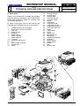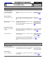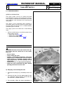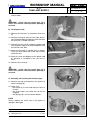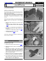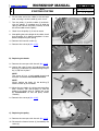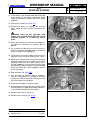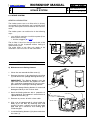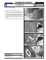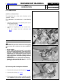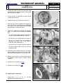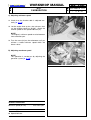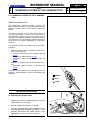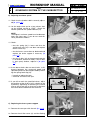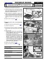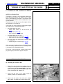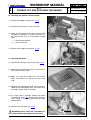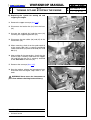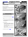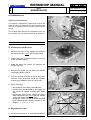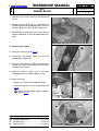
1
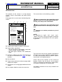
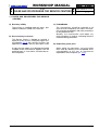
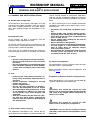
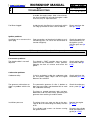
SV150
by
WORKSHOP
MANUAL
Rel. 1.0 - 01/2005
The manufacturer reserves the right to make all the necessary technical or commercial improvements to its products, so
there may be some differences between the series of lawnmowers and the contents of this manual. However the basic specifications and different operating procedures will remain the same.
<= ...BACK... <=
WORKSHOP MANUAL
i.0
TABLE OF CONTENTS
MAIN CHAPTERS
SV 150
2004 to ••••
page 1 / 1 from
ening torques, expendable materials and spare
parts available.
1. Rules and procedures for Service Centres
This chapter covers all the main aspects of the
relationship between the manufacturer and the
service centres.
A close collaboration between the manufacturer
and the service centres is conclusive for solving
problems in the most effective way as well as
maintaining an image of efficiency and reliability.
Compliance with these brief and simple guidelines will facilitate this task and prevent general
misunderstandings and time-wasting for both
the manufacturer and the service centre.
4. Engine tuning
This chapter describes how to plan a maintenance program and outlines a servicing procedure for general engine tuning.
5. Troubleshooting
This chapter summarizes all the main operating
faults and indicates probable causes and procedures for solving them.
2. General and safety regulations
This chapter covers the main aspects of a servicing procedure and the general rules for guaranteeing a successful service which protects the
environment and respects the safety of both the
serviceman and the user of the apparatus.
3. Technical data and specifications
This chapter summarizes all the technical information regarding the engine, tuning data, tight-
6. Servicing procedures
This chapter describes the servicing procedures
for dealing with the most frequent operating
faults.
The descriptions follow a logical sequence and
may cover operations not strictly linked to the
one described.
In this case, you should read the entire procedure carefully so that you can leave out any irrelevant operations without missing necessary
steps.
CONTENTS
ii 0
Introduction
1.1 0
Rules and procedures for Service Centres
2.1 0
General and safety regulations
3.1 0
Technical data and specifications
4.1 0
Testing and tuning the engine
5.1 0
Troubleshooting
6.1
6.2
6.3
6.4
6.5
6.6
6.7
6.8
6.9
Tank and supply
Starting system
Intake system
Carburation
Carburettor governor system
Ignition system
Turning off and stopping the engine
Exhaust system
Engine block
0
0
0
0
0
0
0
0
0
01/2005
WORKSHOP MANUAL
<= ...BACK... <=
SV 150
ii.0
INTRODUCTION
2004 to ••••
page 1 / 1 from
INTRODUCTION
The purpose of this manual is to help Service
Centres service, disassemble and repair SV150
engines.
Each page of this manual states the following information:
G
B
G
WORKSHOP MANUAL
C
from
2004 to ••••
1/2
page
F
6.3 INTAKE SYSTEM
GENERAL INFORMATION
The intake system uses an air filter which is directly
connected to the carburettor and a manifold which
conveys the air/petrol mixture towards the induction
valve.
E
The intake system can malfunction in the following
ways:
•
no or difficult starting or insufficient power (if not
due to other causes):
= Air filter clogged [ 6.3.A];
The air filter is found on the right hand side of the
engine and can be inspected without having to
remove other parts.
The entire body of the filter only needs to be
removed in case of access to the carburettor.
Warns of operations that should be carried
out with utmost care to avoid impairing the functionality and safety of the lawnmower.
SV 150
6.3.0
INTAKE SYSTEM
A
The manual refers to the following symbols:
2
F
1
Warns of operations that should be carried
out with utmost care to avoid injury to the operator.
Reference to another procedure or part of
the manual.
3
1
SERVICING PROCEDURES
NOTE
All references to “right”, “left”, “front”, “rear”,
“upper” and “lower” refer to the engine installed on
the lawnmower and viewed from the user’s operating position.
A) Maintenance of filtering element
1
Clean the area around the filter cover (1).
2
Remove the cover (1) by releasing the rear flap
(2) and remove the sponge filtering element (3).
4
IMPORTANT! The filtering element must be
kept clean and soaked in oil. Replace it if broken, cracked or fragmented. Do not use compressed air for cleaning the filtering element.
3
Wash the sponge filtering element in water and
detergent and dry it with a clean cloth.
4
Soak the filtering element with 2 spoonfuls of
clean engine oil and squeeze it several times to
spread the oil evenly (4).
5
Remove any excess oil with a clean cloth.
6
With a jet of compressed air, clean inside the
body (5) of the filter by removing dust and
remains of grass, making sure that the intake
pipe hole (6) is closed so that nothing gets
inside the pipe.
7
Install the filtering element (3) in place and close
the cover (1).
3
6
5
D
01/2005
A) Engine type or types the page is referring to.
B) Page number, specifically:
– the first two figures separated by a point indicate the section and the chapter
– the third figure indicates the modification
index.
C) Temporary validity of the page, with reference to
the year of manufacture [ 3.1.A] or serial
numbers.
The manual has left out the simplest and quickest
operations that can be handled by a good mechanic, while concentrating more on specific aspects
and the best servicing procedures.
D) Date of release.
E) Page number and total number of pages dedicated to the subject.
Please read all the contents of this manual to
become familiar with the basics of the engine,
which is fundamental for operating in a logical manner without making errors or wasting time.
F) Any previous or ensuing pages dedicated to the
subject.
G) Any chapters before or after the current one.
All problems related to use are fully covered in the
user manual.
01/2005
<= ...BACK... <=
WORKSHOP MANUAL
1.1.0
RULES AND PROCEDURES FOR SERVICE CENTRES SV 150
2004 to ••••
page 1 / 1 from
1.1 RULES AND PROCEDURES FOR SERVICE
CENTRES
A) Warranty validity
The warranty is supplied under the terms, procedures and limits stated in the contract.
B) Post-warranty assistance
The Service Centre is obliged to compile a
report for every service, stating the engine serial number[ 3.1.A], the summary of claims, the
operation carried out and any spare parts used.
A copy of these reports must be kept and made
available to the manufacturer together with the
replaced parts, in case clients should make further complaints.
C) Fault notification
The manufacturer should be informed of all
faults that recur frequently; this allows it to carefully examine the problem and make corrections
on the production line.
Similarly, the manufacturer shall report any
faults traced on its engines, indicating the best
troubleshooting procedure.
D) Requesting spare parts
When asking for spare parts, you must quote
their code by referring to the exploded views
corresponding to the year of manufacture
reported on the nameplate [ 3.1.A].
01/2005
<= ...BACK... <=
WORKSHOP MANUAL
2.1.0
GENERAL AND SAFETY REGULATIONS
2.1 GENERAL AND SAFETY REGULATIONS
A) Qualification of operators
All maintenance, disassembly and repairs must be
carried out by expert mechanics who are familiar
with all the accident prevention and safety regulations after reading through the procedures in this
manual.
B) Safety measures
All the engines are built in conformity with the
European safety regulations in force.
To maintain initial safety levels in the long term, the
Service Centre should take proactive measures by
making checks whenever possible.
Every time you are asked to service the engine (or
the lawnmower on which it is installed), you should:
SV 150
2004 to ••••
page 1 / 1 from
normal hazard related to mechanical operations
and that can be avoided by taking the necessary
care and attention normally required for this type of
work.
As well as following the usual accident prevention
regulations that apply to most repair shops, we recommend you:
– disconnect the spark plug cap before servicing;
– protect hands with suitable working gloves,
especially when working near the cutting unit;
– check that you do not cause accidental petrol
leaks or other losses;
– do not smoke when working on the tank or
when handling petrol;
– do not inhale oil or petrol fumes;
– clean up all traces of spilt petrol immediately;
– test the engine in a well-ventilated environment or where there are adequate exhaust
fume extraction systems;
– do not pollute the environment with oil, petrol
or other waste and dispose of all waste in
accordance with the laws in force.
1) check:
– that the safety devices function correctly;
– that the guards and covers have not been
removed;
– that the nameplates or specification labels
have not been removed or made illegible,
as they form an integral part of the safety
devices.
D) Necessary equipment
All the operations can be carried out with the tools
normally used in a good garage.
Some operations require special equipment and
tools [ 3.1.F].
2) also:
– make sure the safety devices function correctly if they have been tampered with or
removed;
– replace ineffective, damaged or missing
guards and covers;
– replace illegible labels;
– do not carry out operations or modifications on the lawnmower or on the engine
that could affect their performance or lead
to an improper or different use from the
one for which it has been designed and
approved;
– warn the customer that the failure to comply with the above points automatically
voids the warranty and the responsibility of
the manufacturer.
E) Symbols and terms used for safety purposes
Some paragraphs in this manual are preceded by
symbols which indicate the following:
Operations that should be carried out with
utmost care to avoid impairing the functionality
and safety of the engine and/or lawnmower on
which it is installed.
Operations that should be carried out with
utmost care to avoid injury to operators.
C) Precautions during servicing
The operations described in this manual do not
entail particularly hazardous situations besides the
“WARNING” stresses the risk of injury to oneself
and others if instructions and regulations are not
observed.
01/2005
<= ...BACK... <=
WORKSHOP MANUAL
3.1.0
TECHNICAL DATA AND SPECIFICATIONS
A) Identification
All the engines have a
serial number stamped
on the right-hand side of
the crankcase; this 9figure code identifies:
• - ••• - •••••
Year of manufacture
Date
Daily progressive number
The serial number must be reported on every
operating sheet in the warranty application and
is fundamental for identifying and ordering spare
parts.
B) Technical data
Piston displacement .................................... 149 cc
Bore ............................................................. 65 mm
Stroke .......................................................... 45 mm
Minimum speed (SLOW) ................ 2200-2500 rpm
Maximum speed (FAST) ................ 2800-3000 rpm
Fuel tank capacity ..................................... 0.8 litres
Oil sump capacity ..................................... 0.6 litres
SV 150
2004 to ••••
page 1 / 2 from
D) Summary of tightening torques
The first number refers to the procedure, while the
number in brackets is an internal reference to the
procedure.
6.1
6.2
6.3
6.3
6.5
6.6
6.8
6.9
6.9
6.9
Conveyor nuts (2) ................................ 4-7
Starter screw (6) .................................. 4-6
Governor bracket screw (7) ................. 6-8
Carburettor screws (8) ......................... 6-8
Cylinder head screws (34) ............... 20-25
Spark plug tightening torque (1) ...... 16-18
Muffler nuts (3) ..................................... 6-8
Cylinder head screws (4) (6) ............ 20-25
Oil drain plug (12) ............................ 18-22
Engine screws (23) .......................... 20-28
Nm
Nm
Nm
Nm
Nm
Nm
Nm
Nm
Nm
Nm
E) Expendable materials
Petrol ........................................... lead-free (green)
minimum leadfree (green) minimum 90N.O.
Engine oil - from 5 to 35 ° C ....... SAE 30
from -15 to +5 °C ..... 5W30 - 10W30
from -25 to + 35°C ... synthetic 5W30
- 10W30
Spark plug ................................... GL4RC Torch or
equivalent
Starter cable ................................ Ø 4.5x2400 mm
F) Special equipment
C) Adjustments
The number refers to the procedure which
describes the servicing operation.
Distance between spark plug
electrodes ............................................. 0.6-0.8 mm
Coil air gap ....................................... 0.25-0.40 mm
Speed indicator ......................................... 6.4 - 6.5
Tester for spark test ........................................... 6.6
Universal tester................................................... 6.7
01/2005
WORKSHOP MANUAL
<= ...BACK... <=
3.1.0
TECHNICAL DATA AND SPECIFICATIONS
G) Spare parts
Below is a list of spare parts available, not including
parts that are easily available or whose replacement
would entail particularly expensive assembly and
disassembly operations.
To order a spare part, refer to the code on the
exploded view regarding the year of manufacture.
1
2
3
4
5
6
7
8
9
10
11
12
13
14
SV 150
Complete Sumec SV 150 engine
Starter/tank conveyor assembly
Tank cap
Starter handle
Deflector
Starter spring
Starter assembly
Starter hook kit
Fuel pipe
Conveyor stud bolt kit
Nut
Oil level pipe assembly
Air filter base
Screw
15
16
17
18
19
20
21
22
23
24
25
26
27
28
29
30
31
32
33
34
35
36
37
38
2004 to ••••
page 2 / 2 from
Filtering element
Air filter cover
Breather pipe
Governor bracket
Governor spring
Spring
Carburettor
Governor tie rod
Carburettor tie rod
Carburettor gasket kit
Governor fin disc kit
Brake
Cable clamp
Screw
Ignition coil
Spark plug cap
Spark plug
Cylinder head gasket
Stud bolt
Muffler gasket
Muffler spacer
Muffler
Nut
Muffler cover
3
4
11
2
16 14 15
5
13
17
1
9
6
7
10
26
23
8
25
12
24
24
29
22 21 24
19
20
28 27
10
34
35
36
38
18
30
31
32
33
37
01/2005
<= ...BACK... <=
WORKSHOP MANUAL
4.1.0
ENGINE TUNING AND TESTING
4.1 ENGINE TUNING AND TESTING
A) Operating guidelines
The instruction manual describes a series of operations for the client to ensure minimum basic maintenance. For operations beyond the client’s capability, the Service Centre should see to keeping the
engine in perfect working order by:
– Tuning the engine whenever possible.
– Recommending the client a routine maintenance
program at set intervals (e.g. at the end of the
season or before a long period of inactivity).
SV 150
2004 to ••••
page 1 / 1 from
C) Functional test
A functional test needs to be carried out at the end
of each servicing operation, to check that the operations made are effective. The test must be performed in compliance with the safety regulations
regarding the use of the lawnmower on which the
engine is installed.
The functional test is carried out as follows.
1. Refuelling and checking the supply system.
When you have refuelled the tank with new petrol,
check the seal of the tank, the cap and the carburettor pipe.
2. Cold start test. With the throttle control in
“CHOKE”, start the engine a few times to check it
runs normally.
B) Engine tuning program
Whenever the Service Centre is asked to service a
lawnmower or tune an engine, it should follow a
series of operations to ensure the engine is kept
fully serviceable.
3. Check the engine rpm. When the engine is hot
enough, check the engine speed with the throttle
control set to “SLOW” and “FAST”; the readings
should be equal to the specifications [ 3.1.B].
Tuning should involve:
4. Hot start test. With the engine hot and the throttle control set to “SLOW”, start the engine a few
times to check it runs normally.
– external blowing and cleaning the cylinder head,
cylinder and muffler by removing any remains of
grass and mud;
– checking the oil level, topping up or replacing
parts if necessary;
5. Engine brake and stopping test. If you release
the lawnmower brake lever, the engine should turn
off instantaneously and decisively, and the rotation
should stop within 3 seconds.
– inspecting the condition of the starter cable and
checking that it functions correctly;
– cleaning and oiling the air filter [ 6.3];
– emptying and cleaning the fuel tank and checking the breather pipe [ 6.1];
If all of these operations have a positive result, the
engine can be considered fully serviceable and be
returned to the client.
– adjusting minimum and maximum speeds [ 6.4
and 6.5];
– inspecting the condition of the spark plug and
ignition cable; checking the distance between the
electrodes [ 6.6];
– tightening the screws [ 6.9];
– functional test [ point “C”].
Should the checks and adjustments fail to achieve
a satisfactory result, refer to chapter 5 for troubleshooting.
01/2005
<= ...BACK... <=
WORKSHOP MANUAL
5.1.0
TROUBLESHOOTING
SV 150
2004 to ••••
page 1 / 5 from
A) The engine does not start
Probable cause
Comment
Solution
Lawnmower problems
The cable control does not activate the coil earth
switch.
Adjust and/or replace
the cable [ 6.7.A]
The microswitch is faulty
If the microswitch remains locked in the pressed
position, it does not stop the coil earth connection.
Replace the
microswitch [ 6.7.B]
Electric current does not reach
the spark plug
The spark plug is badly connected, faulty or the
electrodes are too far away.
The coil is faulty and does not supply current or
the air gap is too large.
Check the spark plug
and the efficiency of
the ignition system
with the spark test [
6.6.A]
Fouling in the combustion
chamber
Fouling in the combustion chamber absorbs the
fresh mixture, which makes starting difficult and
may impair valve closure.
Dismount the cylinder
head and remove fouling [ 6.9.A]
Insufficient pressure
The cylinder head screws can loosen causing
the gasket to burn.
Dismount the cylinder
head and replace the
gasket [ 6.9.A]
The piston rings can wear out due to the passage of dust caused by an excessively dirty or
unoiled air filter or overheating due to the lack of
oil.
Change the engine
[ 6.9.C]
The engine brake cable is
faulty or unfastened
Electrical problems
Engine block problems
B) The engine starts badly or kicks back
Probable cause
Comment
Solution
The loose blade stops the effect of the flywheel
and the kick-back can make starting difficult.
Check that the lawnmower blade and hub
are securely fastened
The clogged filter can thicken the mixture flooding the engine.
Check and clean the
air filter [ 6.3.A]
Lawnmower problems
The lawnmower blade is loose
Intake problems
Air filter is clogged up
01/2005
WORKSHOP MANUAL
<= ...BACK... <=
5.1.0
TROUBLESHOOTING
SV 150
2004 to ••••
page 2 / 5 from
Carburation problems
Carburettor is dirty
If the jet and the pipes inside the carburettor clog
up, the petrol flow drops and the engine fails to
function correctly.
Check and clean the
carburettor [ 6.4.A]
Poor seal of carburettor needle
valve
If the needle valve does not close, excess fuel in
the float chamber can reach the combustion
chamber through the intake manifold. This can
flood the engine and be hazardous as the petrol
can seep through the rings and reach the oil
sump. When mixed with petrol, oil loses its lubricating properties and the engine deteriorates
rapidly.
Clean the carburettor
housing and needle
valve [ 6.4.A] or
replace the carburettor
[ 6.4.B]
Choke blocked
The choke can get blocked in the closed position if the mixture is too oily.
Check and clean the
carburettor [ 6.4.A]
and the choke
C) Starting is difficult and strains the cable
Probable cause
Comment
Solution
Lawnmower problems
The lawnmower traction cable
(if present) is bent, jammed or
poorly adjusted
The engine must start with the lawnmower drive
completely disengaged; a poorly adjusted cable
can generate faulty resistance which makes
starting more difficult.
Check and/or adjust
the lawnmower traction cable
If the engine is tilted with the spark plug at the
bottom, oil may seep into the cylinder head
through the rings. This causes excess pressure
and a reduction of mixture in the combustion
chamber.
Dismount the cylinder
head and clean it [
6.9.A]
Problems caused by the
engine
Oil in the cylinder head
D) The engine starts but does not run
Probable cause
Comment
Solution
Supply problems
The tank cap has a clogged
breather pipe
The clogged breather pipe in the tank stops the
regular flow of fuel into the carburettor float
chamber. When the fuel has run out in the float
Clean and/or replace
the cap [ 6.1.C]
01/2005
WORKSHOP MANUAL
<= ...BACK... <=
5.1.0
TROUBLESHOOTING
SV 150
2004 to ••••
page 3 / 5 from
chamber, the engine stops. After a few minutes,
the float chamber fills up and the engine is able
to restart, only to stop soon after.
Fuel filter clogged
Inside the tank, the filter has a metal mesh which
can clog up with dirt or with a film of old fuel.
Empty and clean the
tank [ 6.1.B]
Poor connections of the electrical cables or malfunctioning parts can cause the lawnmower to
function irregularly.
Check the spark plug
and the efficiency of
the ignition system
with the spark test [
6.6.A]
Ignition problems
Insufficient or no current to the
spark plug
E) The engine is inefficient (insufficient power)
Probable cause
Comment
Solution
Lawnmower problems
The throttle’s “FAST” position may not correspond with the carburettor’s “FAST” position,
reducing the flow of mixture and hence the
power.
Check and/or adjust
the throttle cable [
6.5.A]
Carburettor dirty
If the jet and pipes inside the carburettor clog
up, the petrol supply drops and the engine
becomes less efficient.
Check and clean the
carburettor [ 6.4.A]
The governor malfunctions or
there is a problem with the tie
rods
The pneumatic governor fin disc is broken or
does not move freely and therefore fails to work
the carburettor correctly.
Check the entire governor system [ 6.5]
The throttle cable is not well
adjusted
Carburation problems
The bent or warped governor rods are bent,
deformed or do not move freely, preventing the
governor from reaching its end-of-stroke.
Insufficient pressure
The piston rings can wear out due to the passage of dust or overheating caused by the lack
of oil.
Replace the engine
[ 6.9.C]
The cylinder head screws can loosen causing
the gasket to burn.
Dismount the cylinder
head and replace the
gasket [ 6.9.A]
01/2005
WORKSHOP MANUAL
<= ...BACK... <=
SV 150
5.1.0
TROUBLESHOOTING
2004 to ••••
page 4 / 5 from
Environmental problems
The engine is used at a high
altitude
The rarefaction of air in the mountains causes a
drop in power of approx. 10-12% every 1000
metres of altitude.
Advise your client to
adapt the strain of the
lawnmower to the limited power available.
F) The engine runs irregularly
Probable cause
Comment
Solution
Air seeps into the carburettor
If air seeps through the gaskets, it can cause the
lawnmower to function poorly and make it difficult to maintain the minimum speed (2200-2500
rpm).
Replace the carburettor gaskets [ 6.4.A]
The governor malfunctions or
there is a problem with the
rods
The pneumatic governor fin disc is broken or
does not move freely and therefore fails to work
the carburettor correctly.
Check the entire governor system [ 6.5]
Carburation problems
The governor rods are bent, deformed or do not
move freely, preventing the governor from reaching its end-of-stroke.
Starting problems
The coil air gap has been
poorly adjusted
The air gap adjustment between the flywheel
and coil must be 0.25-0.40 mm.
Adjust the air gap [
6.6.B] and if the problem persists, replace
the coil [ 6.6.C]
G) The engine overreved
Probable cause
Comment
Solution
Carburation problems
Governor blocked
Excess dirt or a broken spring can impede the
movements of the governor or impede return.
Check the governor
[ 6.5.B]
H) The engine does not turn off
Probable cause
Comment
Solution
Lawnmower problems
The engine brake cable is bent
or jammed
When the lever is released,
microswitch is not pressed.
the
earth
Check and/or adjust
the cable [ 6.7.A]
01/2005
WORKSHOP MANUAL
<= ...BACK... <=
5.1.0
TROUBLESHOOTING
SV 150
2004 to ••••
page 5 / 5 from
Electrical problems
The earth cable is disconnected or broken
The broken or disconnected cable prevents the
microswitch from closing the electric circuit to
earth
Check the earth connection [ 6.7.B]
J) The engine judders
Probable cause
Comment
Solution
Blade not balanced
The imbalanced or loose blade causes judders
and the premature wear of all the parts inside the
engine.
Dismount and balance
the blade and tighten
the screws to the
specified levels
Engine screws loose
An engine with loose screws can be hazardous
for the user and can break internal parts.
Tighten the screws to
the specified levels [
6.9.C]
Lawnmower problems
K) The engine does not stop within 3 seconds after it has turned off
Probable cause
Comment
Solution
Problems with the stopping
system
Faulty or no clutch lining
The thickness of the clutch lining normally guarantees good braking action for the entire duration of the engine.
Replace the engine
stopping system [
6.7.D]
If it comes away from the lever, act immediately
to stop the metal from rubbing against the flywheel causing hazardous sparks.
01/2005
<= ...BACK... <=
WORKSHOP MANUAL
SV 150
6.1.0
TANK AND SUPPLY
2004 to ••••
page 1 / 2 from
6.1 TANK AND SUPPLY
GENERAL INFORMATION
The supply system consists of a petrol tank (built
into the upper conveyor) connected to the carburettor by a pipe. A mesh filter on the bottom of the tank
stops deposits and impurities from reaching the
carburettor.
The supply to the carburettor float chamber is
caused by gravity and the volume of petrol taken
from the tank as the engine runs is compensated by
a breather pipe in the cap.
The supply system can malfunction in the following
ways:
•
difficult or failed start or insufficient power (if not
due to other causes):
= Petrol filter dirty [ 6.1.B];
= Petrol pipes clogged;
= Inefficient breather pipe [ 6.1.C].
SERVICING PROCEDURES
6
WARNING! All work on the tank and on the supply system must be carried out in safe conditions, so:
2
2
1
– do not smoke;
– always empty the tank;
– work in a ventilated environment away from
naked flames or unprotected sources of heat;
– collect petrol in a suitable container with a
cap using a funnel and avoid spilling it on the
work bench;
– remove all traces of spilt petrol immediately;
– check you have connected the pipes before
pouring petrol back into the tank
2
4
A) Emptying and removing the tank
1
Remove the conveyor (1) secured by three nuts
(2).
2
Remove the ring (3) of the petrol pipe (4) from
the carburettor side and drain all the fuel from
the tank into a suitable container.
3
For assembly, follow the above procedures in
3
01/2005
<= ...BACK... <=
WORKSHOP MANUAL
SV 150
6.1.0
TANK AND SUPPLY
2004 to ••••
page 2 / 2 from
reverse order.
WARNING! Check that the petrol pipe (4) is
intact and secured correctly before pouring in
new fuel.
5
B) Cleaning the tank
11 Remove the conveyor (1) secured by three nuts
(2).
4
12 Remove the ring (5) from the tank side, disconnect the petrol pipe (4) and drain all the fuel from
the tank into a suitable container.
13 Remove the tank cap (6) and blow compressed
air through the tube (7) to remove deposits from
the internal mesh filter.
14 Keep the tube hole (7) closed, pour in approx.
100 cl of clean petrol and shake well to clean
inside the tank.
7
15 Empty the tank and dispose of the petrol used
for cleaning in accordance with the laws in
force.
16 Remount the conveyor.
WARNING! Check that the petrol pipe (4) is
intact and secured correctly before pouring in
new fuel.
6
8
C) Checking and cleaning the breather pipe
21 Remove the cap (6) and pull out the gasket (8)
and the sponge (9).
22 Check that:
– the gasket (8) is intact and without cracks or
fissures;
– the air passages (10) inside the cap are not
clogged;
– the sponge (9) is not crushed or broken.
6
NOTE
Always replace the entire cap if the gasket or
sponge is damaged.
10
8
9
Tightening torques
2
Conveyor nuts ...................................... 4-7 Nm
01/2005
<= ...BACK... <=
WORKSHOP MANUAL
SV 150
6.2.0
STARTING SYSTEM
2004 to ••••
page 1 / 3 from
6.2 STARTING SYSTEM
GENERAL INFORMATION
The starting system is built into the upper conveyor
(which also includes the tank) and consists of a
cable wound onto a pulley.
The movement from the pulley to the flywheel (and
the engine shaft) is transmitted by a pair of hooks.
The cable is returned and rewound by a spiral
spring.
2
1
Other than the possibility of the cable breaking, the
starting system may malfunction in the following
ways:
•
failed start after attachment (if not due to other
causes):
= cable too short, therefore does not supply
adequate number of revs to the engine [
6.2.A].
•
the pulley is not attached to the flywheel. This
can be detected when the cable unwinds without strain :
= the hooks are deformed or broken [ 6.2.B].
•
inefficient or no return of the cable:
= spring broken [ 6.2.C].
4
3
In all cases, remove the conveyor to make the necessary checks or repairs.
3
SERVICING PROCEDURES
4
A) Replacing the cable
1
Remove the conveyor with the tank [ 6.1.A].
2
Remove the internal screen (1) fastened by the
screw (2).
3
Keep hold of the pulley (3) and slowly unwind
(clockwise) the entire cable (4) to gradually
release the return spring. If the cable breaks, the
spring will be already released and you will only
have to unwind the cable.
4
Undo or cut the knot at the end of the cable or
remove the section still attached to the pulley.
5
Cut a section of cable (4) (Ø 4.5 mm and 2.40 m
long), fit one end in the pulley hole (3) and make
a knot to prevent it from slipping out.
4
5
01/2005
<= ...BACK... <=
WORKSHOP MANUAL
SV 150
6.2.0
STARTING SYSTEM
6
Fit the other end of the cable in the conveyor
hole, securing it to the handle (5) with a knot.
7
Turn the pulley (3) and the cable (4) anticlockwise for approx. 5 complete revs to load the
spring, then release the pulley carefully to wind
the entire cable onto the pulley.
8
Check that the pulley (3) is free to rotate.
2004 to ••••
page 2 / 3 from
3
4
9
After pulling the entire length of the cable, check
that the pulley (3) is able to complete 2-3 turns
before compressing the spring.
10 Remount the internal screen (1).
11 Remount the conveyor [ 6.1.A].
3
6
8
B) Replacing the hooks
21 Remove the conveyor with the tank [ 6.1.A].
7
22 Loosen the central screw (6) and dismount the
bushing (7) and hooks (8) without letting the pulley (3) slip out of place.
NOTE
The screw (6) has a left-handed thread and
therefore should be unscrewed clockwise.
8
NOTE
Always replace the hooks (8), the bushing (7)
and the screw (6) in one block.
23 Mount the new hooks (8), taking care to position
them correctly with the bushing (7) and the
guides in the pulley hub (3). Tighten the screw
(6) anticlockwise so that the pulley rotates
smoothly.
8
7
24 Remount the conveyor [ 6.1.A].
6
C) Replacing the pulley
31 Remove the conveyor with the tank [ 6.1.A].
7
8
32 Dismount the internal screen (1) fastened by the
screw (2).
01/2005
<= ...BACK... <=
WORKSHOP MANUAL
SV 150
6.2.0
STARTING SYSTEM
2004 to ••••
page 3 / 3 from
33 If the spring is not already released, keep hold
of the pulley (3) and slowly unwind the entire
cable (4) clockwise to release the return spring
gradually.
34 Dismount the hooks [ point “B”].
9
35 Remove the pulley (3), making sure that the
return spring (9) stays in place underneath the
pulley.
3
WARNING! Carry out this operation with
utmost care to avoid injury when the spring
suddenly unwinds, as it could slip out of
place.
36 Clean the inside of the conveyor with degreasing liquid by removing any leftover dirt or
grease.
9
37 Cut a section of cable (4) (Ø 4.5 mm and 2.40 m
long), fit one end in the pulley hole (3) and make
a knot to stop it from slipping out.
38 Fit the other end of the cable in the conveyor
hole and secure it to the handle (5) with a knot.
39 Spray some silicone lubricant onto the spring (9)
and apply liquid grease to inside the conveyor
housing. Check that the spiral spring (10) is
securely lodged in the conveyor housing and
put the pulley (3) back in place so that the inside
end of the spring (9) is firmly lodged in the slot
on the conveyor.
40 Refit the hooks [ point “B”].
41 Turn the pulley (3) and the cable (4) anticlockwise for 5 complete turns in order to load the
spring, then release the pulley carefully to wind
the entire cable onto the pulley.
10
42 Check that the pulley (3) rotates freely.
43 After pulling the entire length of the cable, check
that the pulley (3) is able to complete another 23 turns before compressing the spring.
44 Remount the internal screen (1).
45 Remount the conveyor [ 6.1.A].
Tightening torques
6
Starter screw ........................................ 4-6 Nm
01/2005
<= ...BACK... <=
WORKSHOP MANUAL
6.3.0
INTAKE SYSTEM
SV 150
2004 to ••••
page 1 / 2 from
6.3 INTAKE SYSTEM
GENERAL INFORMATION
The intake system uses an air filter which is directly
connected to the carburettor and a manifold which
conveys the air/petrol mixture towards the induction
valve.
The intake system can malfunction in the following
ways:
•
no or difficult starting or insufficient power (if not
due to other causes):
= Air filter clogged [ 6.3.A];
The air filter is found on the right hand side of the
engine and can be inspected without having to
remove other parts.
The entire body of the filter only needs to be
removed in case of access to the carburettor.
2
1
3
1
SERVICING PROCEDURES
A) Maintenance of filtering element
1
Clean the area around the filter cover (1).
2
Remove the cover (1) by releasing the rear flap
(2) and remove the sponge filtering element (3).
4
IMPORTANT! The filtering element must be
kept clean and soaked in oil. Replace it if broken, cracked or fragmented. Do not use compressed air for cleaning the filtering element.
3
Wash the sponge filtering element in water and
detergent and dry it with a clean cloth.
4
Soak the filtering element with 2 spoonfuls of
clean engine oil and squeeze it several times to
spread the oil evenly (4).
5
Remove any excess oil with a clean cloth.
6
With a jet of compressed air, clean inside the
body (5) of the filter by removing dust and
remains of grass, making sure that the intake
pipe hole (6) is closed so that nothing gets
inside the pipe.
7
Install the filtering element (3) in place and close
the cover (1).
3
6
5
01/2005
<= ...BACK... <=
WORKSHOP MANUAL
6.3.0
INTAKE SYSTEM
SV 150
2004 to ••••
page 2 / 2 from
B) Removing the filter body
11 Clean the area around the filter cover (1).
12 Remove the cover (1) by releasing the rear flap
(2) and take out the sponge filtering element (3).
2
13 To remove the filter body (5), loosen the screw
(7) fastening the governor system bracket and
the two screws (8), remembering that both these
screws also fasten the carburettor to the engine
block.
1
14 Disconnect the oil vapour circulation pipe (9).
5
3
5
8
8
7
9
Tightening torques
7
8
Governor bracket screw ...................... 6-8 Nm
Carburettor screw ................................ 6-8 Nm
01/2005
<= ...BACK... <=
WORKSHOP MANUAL
SV 150
6.4.0
CARBURATION
2004 to ••••
page 1 / 3 from
6.4 CARBURATION
GENERAL INFORMATION
The carburettor has a float with a fixed jet and a
“CHOKE” control.
The carburettor can malfunction in the following
ways:
•
difficult or failed start or insufficient power (if not
due to other causes):
= Carburettor dirty [ 6.4.A].
•
engine runs irregularly (if not due to other causes):
= Air has seeped into the carburettor [
6.4.A].
1
4
2
3
SERVICING PROCEDURES
WARNING! All operations on the tank and supply
system must be carried out in safe conditions,
so:
– do not smoke;
– always empty the tank if petrol is not strictly
necessary for the operation to be carried out;
– work in a ventilated environment away from
naked flames or unprotected sources of heat;
– collect petrol in a suitable container with a
cap using a funnel and avoid spilling it on the
work bench;
– remove all traces of spilt petrol immediately;
– check you have connected the pipes before
pouring petrol back into the tank.
13
6
5
8
A) Removing and cleaning the carburettor
1
Remove the conveyor with the tank. [ 6.1.A].
2
Remove the air filter [ 6.3.B].
3
Disconnect the two tie rods (1) and (2) and take
the carburettor (3) out of the intake manifold (4).
7
9
01/2005
<= ...BACK... <=
WORKSHOP MANUAL
4
SV 150
6.4.0
CARBURATION
2004 to ••••
page 2 / 3 from
Loosen the central screw (5) fastening the float
chamber (6) and carefully collect all the petrol
left in the float chamber.
10
5
Pull out the pin (7), dismount the float (8) and
remove the gasket (9).
11
6
Undo the screw (10) and pull out the jet (11).
10
9
7
Clean the jet and the carburettor thoroughly by
immersing them in clean petrol (or a detergent)
for 24 hours. Dry with compressed air, blowing
well through the carburettor holes.
8
Mount the carburettor following the previous
points 6, 5 and 4 in reverse order, remembering
that:
12
– It is always advisable to replace the gasket (9)
and the washer underneath the screw (5);
– the float (8) must oscillate freely on the pin (7);
– the jet (11) should never be modified or
replaced with others even if they seem to
have the same specifications;
13
– the choke (12) must open and close regularly;
– the float chamber drain screw (13) must be
facing forwards.
14
9
When fitting the carburettor back on the engine,
always replace the grommet (14) on the manifold side and the gasket (15) on the filter side.
10 Remount the tie rods (1) and (2) and check that
the governor system moves smoothly without
stopping.
11 Remount the conveyor [ 6.1.A].
12 Remount the air filter [ 6.3.B].
15
B) Replacing the carburettor
–
Follow steps 1 - 2 - 3 - 9 - 10 - 11 - 12 of the
procedure described in point “A”.
01/2005
<= ...BACK... <=
WORKSHOP MANUAL
6.4.0
CARBURATION
SV 150
2004 to ••••
page 3 / 3 from
C) Adjusting minimum speed
21 Check that the throttle cable is adjusted correctly [ 6.5.A].
22 Let the engine heat up for a few minutes, then
set the throttle control to “SLOW”. Check the
rotation speed on the speed indicator (21).
21
NOTE
The engine’s minimum speed must be between
2200 and 2500 rpm.
23 Turn the screw (22) on the carburettor until you
achieve a stable minimum speed within the
above values.
D) Adjusting maximum speed
22
NOTE
This operation is carried out by adjusting the
governor system [ 6.5.B].
Technical information
Minimum speed (SLOW) .............. 2200-2500 rpm
Special equipment
21 Speed indicator
01/2005
<= ...BACK... <=
WORKSHOP MANUAL
6.5.0
GOVERNOR SYSTEM OF THE CARBURETTOR
SV 150
2004 to ••••
page 1 / 3 from
6.5 GOVERNOR SYSTEM OF THE CARBURETTOR
GENERAL INFORMATION
The carburettor’s governor system consists of a
lever system mounted on a support attached to the
engine’s cylinder head, with a built-in pneumatic
device.
This device consists of a fin disc which tends to
close the carburettor’s choke under the pressure of
the flywheel air, against the main spring of the control lever. The balance between the throttle control
and the push of air on the fin disc adapts the flow of
mixture into the engine depending on the power
required.
The governor system can malfunction in the following ways:
•
difficult or failed start or insufficient power (if not
due to other causes):
= Incorrect adjustment of the throttle cable [
6.5.A];
= rods bent or deformed [ 6.5.B];
= pneumatic device broken or blocked [
6.5.B].
•
Engine runs irregularly (if not due to other causes):
= pneumatic device broken or blocked [
6.5.B].
A visual inspection allows you to rapidly identify any
broken or deformed parts, which should always be
replaced.
CHOKE
FAST
SLOW
SERVICING PROCEDURES
A) Adjusting the throttle cable
1
Loosen the screw (1) of the clamp (2) so that the
cable sheath (3) runs freely.
2
Set the throttle control lever to “SLOW”.
3
Push the speed governor lever forward as far as
reaching the end of stroke (4), keep it in this
position and secure the cable sheath (3) by
tightening the screw (1) of the clamp (2).
1
3
4
2
01/2005
<= ...BACK... <=
WORKSHOP MANUAL
SV 150
6.5.0
GOVERNOR SYSTEM OF THE CARBURETTOR
2004 to ••••
page 2 / 3 from
B) Adjusting maximum speed
11 Check that the throttle cable is correctly adjusted [ point “A”].
12 Let the engine heat up for a few minutes then
set the throttle control to “FAST”. Check the
rotation speed on the speed indicator (21).
21
NOTE
The engine’s maximum speed must be between
2800 and 3000 rpm; if you do not read this
value, proceed as follows.
13 Check:
– that the spring (22) is intact and that the
spring hook wire (23) is not bent and replace
them if necessary;
24
– that the levers are not bent or deformed and
replace the entire support if necessary [
point “C”];
– that the fin disc (24) of the pneumatic device
is not broken and moves freely. If the fin disc
is even partly broken, replace it [ point
“D”];
22
14 If the above checks do not reveal faults, a difference between the measured speed and
specified speed can be compensated by bending the spring hook clip (25):
26
23
– inwards to reduce the rpm:
– outwards to increase the rpm.
15 If you fail to reach the specified values, adjust
the position of the fin disc (24) in relation to the
flywheel by tightening or loosening the central
ring on the tie rod (26) to increase or decrease
the centre distance between the terminals.
24
26
C) Replacing the lever system support
21 Remove the conveyor with the tank [ 6.1.A].
25
22 Remove the air filter cover (31) and the filtering
01/2005
<= ...BACK... <=
WORKSHOP MANUAL
SV 150
6.5.0
GOVERNOR SYSTEM OF THE CARBURETTOR
2004 to ••••
page 3 / 3 from
element (32), then loosen the screw (33).
23 Loosen the three screws (34) fixing the support
(35) to the cylinder head, then remove the support (35) by unhooking the spring (36) from the
fin disc (37) and the tie rod (38).
24 When mounting, remember to tighten the
screws (34) to the specified levels and avoid a
drop in pressure with the risk of burning the
cylinder head gasket. We therefore recommend
checking the other five cylinder head screws
too.
32
33
25 Remount the conveyor [ 6.1.A].
31
34
D) Replacing the fin disc on the pneumatic
device
34
34
31 Remove the conveyor with the tank [ 6.1.A].
32 Unhook the spring (36).
35
34 Dismount the fin disc (37) which is fastened by
the screw pin (39) and disconnect the tie rod
(40).
35 When mounting,
– Make sure the washer (41) is correctly positioned underneath the fin disc (37) and
securely tighten the pin (39) in such a way
that the fin disc (37) moves freely;
– Check that the tie rod (40) has a centre distance between the ends that brings the fin
disc (37) to a distance of 13-15 mm from
external surface of the flywheel (42).
Otherwise tighten or loosen the central ring
on the tie rod until you achieve the right distance. This tie rod adjustment should be considered “preliminary” and can be altered during maximum speed adjustment.
39
38
37
40
41
36 Remount the conveyor [ 6.1.A].
36
37 Adjust the maximum speed [ point “B”].
40
Tightening torques
34 Cylinder head screws ....................... 20-25 Nm
Technical information
40
Maximum speed (FAST) ................ 2800-3000 rpm
42
13-15 mm
Special equipment
21 Speed indicator
37
01/2005
<= ...BACK... <=
WORKSHOP MANUAL
6.6.0
IGNITION SYSTEM
SV 150
2004 to ••••
page 1 / 3 from
6.6 IGNITION SYSTEM
GENERAL INFORMATION
The ignition system has a flywheel with an electronic coil which supplies high voltage to the spark plug.
The starting system can malfunction in the following
ways:
•
the engine does not start (if not due to another
cause):
= no spark on the spark plug due to a faulty coil
[ 6.6.A];
= coil to earth [ 6.6.B and 6.7.B];
= incorrect adjustment of the air gap [ 6.6.B];
= faulty spark plug or wrong distance between
the electrodes [ 6.6.A];
= oxidized or loose contacts [ 6.6.B].
•
the engine runs irregularly (if not due to another
cause):
= incorrect adjustment of the air gap [ 6.6.B];
= oxidized or loose contacts [ 6.6.B].
For access to the coil and the flywheel, remove the
upper conveyor.
SERVICING PROCEDURES
A) Checking the efficiency of the ignition system
1
Dismount the spark plug (1) and look at the
colour on the end of the thread. This can give
you a good idea of the carburation:
– black = mixture too greasy due to clogged air
filter;
– nut brown = regular carburation.
Replace the spark plug if the electrodes (2) are
burnt or if the porcelain is broken or cracked.
2
0,6-0,8
mm
WARNING! Fire hazard:
– do not check the ignition system if the spark
plug is not screwed in place;
– always use the specific tool for the spark test.
2
Connect the tester (3) to the spark plug cap (4)
1
01/2005
<= ...BACK... <=
WORKSHOP MANUAL
6.6.0
IGNITION SYSTEM
SV 150
2004 to ••••
page 2 / 3 from
and to earth on the engine (5). Activate the
starter and see in the instrument if the spark
jumps.
3
If the test has a positive result, clean the electrodes (2) with compressed air and adjust the
distance to 0.6-0.8 mm. Remount the spark
plug and tighten it to the specified levels.
5
Otherwise, check the system parts as described
in point “B”.
4
3
B) Adjusting the air gap and checking the coil
12
11 Remove the conveyor with the tank [ 6.1.A]
12 Make sure that the cable faston is not oxidized;
if it is, disconnect, clean and remount it, spraying it with a special antioxidant.
13 Check that the black earth cable (11) of the coil
(12) is intact and that the insulation is not
crushed due to incorrect assembly.
The black spark plug cable should not have any
cracks or signs of deterioration or burns which
reduce its efficiency and insulation level.
14 Loosen the two screws (13) securing the coil
(12), release the brake manually and rotate the
flywheel (14) until the magnetic inserts are lined
up with the poles of the coil core (12).
15 Insert a 0.35 mm thickness gauge (15) between
the flywheel (14) and the coil poles. Push the
coil until the poles come in contact with the
thickness gauge and secure both screws (13).
Tighten the screws remembering that the air
gap must be between 0.25 and 0.40 mm.
11
13
12
13
15
14
NOTE
An accurate inspection of the efficiency of a coil can
only be carried out in a laboratory equipped with a
oscilloscope. To make a brief check, proceed as follows:
16 Disconnect the faston of the black earth cable
(11) and reposition the upper conveyor to activate the starter.
11
01/2005
<= ...BACK... <=
WORKSHOP MANUAL
6.6.0
IGNITION SYSTEM
SV 150
2004 to ••••
page 3 / 3 from
17 Carry out a spark test as described in point “A”:
– If the spark jumps = the coil functions correctly, so if the system malfunctions, it is due
to the earth microswitch or relative cable [
6.7.B];
17
16
– If the spark does not jump = the coil is faulty
and must be replaced [ point “C”].
18 Remount the conveyor [ 6.1.A].
C) Replacing the coil
21 Remove the conveyor with the tank [ 6.1.A].
13
22 Disconnect the faston of the earth cable (11).
23 Dismount the metal spark plug cap (16).
12
24 Undo the two screws (13) and take out the coil
(12).
25 Mount the new coil without tightening the two
screws (13) and turn the flywheel (14) until the
magnetic inserts are lined up with the poles of
the coil core (12).
26 Insert a 0.35 mm thickness gauge (15) between
the flywheel (14) and the coil poles. Push the
coil until the poles come in contact with the
thickness gauge and secure both screws (13).
Tighten the screws remembering that the air
gap must be between 0.25 and 0.40 mm.
13
15
14
27 Remount the spark plug cover (16), screw it
firmly onto the end of the black cable (17) and
connect the earth cable faston (11).
28 Remount the conveyor [ 6.1.A].
Tightening torques
1
Spark plug tightening torque ........... 16-18 Nm
Technical information
Type of spark plug ..... GL4RC (Torch) or equivalent
Distance between electrodes .............. 0.6-0.8 mm
Coil/flywheel air gap ........................ 0.25-0.40 mm
Special equipment
3
Tester for spark test
01/2005
<= ...BACK... <=
WORKSHOP MANUAL
6.7.0
TURNING OFF AND STOPPING THE ENGINE
SV 150
2004 to ••••
page 1 / 3 from
6.7 TURNING OFF AND STOPPING THE ENGINE
GENERAL INFORMATION
The engine is turned off and stopped by releasing a
lever on the lawnmower. The cable acts on a lever
which simultaneously activates a microswitch that
sends the coil to earth as well as a brake which acts
on the flywheel.
The brake must be able to stop the engine within 3
seconds after it is turned off.
The system for turning off and stopping the engine
can malfunction in the following ways:
•
the engine does not start:
= brake cable broken or disconnected [
6.7.A];
= faulty switch [ 6.7.B];
= earth cable has deteriorated.
•
the engine does not turn off:
= brake cable bent or jammed [ 6.7.A];
= faulty switch or disconnection [ 6.7.B].
•
the engine does not stop within 3 seconds after
it is turned off:
= clutch lining has come away [ 6.7.C].
If the microswitch malfunctions or if the brake lining
has come away, replace the entire assembly which
is mounted on a supporting bracket.
For access to the system for turning off and stopping the engine, remove the upper conveyor.
SERVICING PROCEDURES
A) Checking the control cable
1
Check that the sheath (1) is not bent, that the
wire (2) is securely connected to both the lawnmower lever and the external hole of the lever
(3) on the engine and that the terminal (4) is correctly fastened to the support (5).
5
3
4
2
Check that the wire (2) runs freely inside the
sheath (1) when you move the lever.
3
Check that the end of the wire (2) is slightly
loose when you release the lawnmower lever.
2
1
01/2005
<= ...BACK... <=
WORKSHOP MANUAL
6.7.0
TURNING OFF AND STOPPING THE ENGINE
SV 150
2004 to ••••
page 2 / 3 from
B) Checking the ignition off microswitch
11 Remove the upper conveyor [ 6.1.A].
12 Disconnect the faston (11) from the coil.
13 Using an Ohmmeter tester, make contact with
the prods on terminals “1-COM” and “3-NO” of
the microswitch (12); the instrument should
read:
11
- ∞ = microswitch pressed
- 0 = microswitch free
14 Remount the upper conveyor [ 6.1.A].
C) Checking the brake
12
21 Remove the conveyor with the tank [ 6.1.A].
22 Check that the clutch lining (13) is at least 2 mm
thick at the thinnest point.
23 Make sure that the control lever (14) moves
freely and remove any remains of grass and
mud.
24 Reconnect the petrol pipe and start the engine.
Release the lawnmower lever and check that
the engine stops within 3 seconds.
25 If it stops after 3 seconds, replace the entire
assembly [ point “D”], because the spring or
clutch lining is unable to guarantee the right
braking times.
13
14
26 Remount the conveyor [ 6.1.A].
WARNING! Never return the lawnmower to
your client without checking brake efficiency.
> 2 mm
01/2005
<= ...BACK... <=
WORKSHOP MANUAL
6.7.0
TURNING OFF AND STOPPING THE ENGINE
SV 150
2004 to ••••
page 3 / 3 from
D) Replacing the system for turning off and
stopping the engine
31 Remove the upper conveyor [ 6.1.A].
25
32 Disconnect the brake wire (21) from the lever
(22).
22
29
33 Unscrew the stud bolt (23) and the screw (24)
fastening the supporting bracket (25).
21
34 Disconnect the two cables (26) and (27) of the
microswitch (28).
23
35 When mounting, check that the eyelet terminal
of the earth cable (26) is correctly positioned
under the bracket (25) and fastened by the stud
bolt (23).
36 After making all the connections, check that the
terminal (29) is correctly fixed onto the support
(25) and that the wire (21) is correctly attached
to the outer hole of the lever (22).
26
24
27
28
25
37 Remount the conveyor [ 6.1.A].
38 Start the engine, release the lawnmower lever
and check that the engine stops within 3 seconds.
25
WARNING! Never return the lawnmower to
your client without checking brake efficiency.
26
Special equipment
–
Universal tester
01/2005
<= ...BACK... <=
WORKSHOP MANUAL
SV 150
6.8.0
EXHAUST SYSTEM
2004 to ••••
page 1 / 1 from
6.8 EXHAUST SYSTEM
2
GENERAL INFORMATION
The exhaust system consists of a muffler installed
on the cylinder together with a gasket, a spacer and
a heatproof baffle.
A malfunctioning exhaust system may lead to a loss
in power or excess noise. However, the muffler is a
preassembled part which cannot and must not be
disassembled or repaired but only replaced.
1
2
SERVICING PROCEDURES
A) Removing and replacing the muffler
1
Remove the conveyor with the tank [ 6.1.A].
2
Remove the cover (1) secured by three screws
(2).
3
Unscrew the two nuts (3) and take out the muffler (4), the heatproof baffle (5), the spacer (6)
and the gasket (7).
4
When mounting:
3
3
4
5
– thoroughly clean the cylinder contact surface,
removing all gasket fragments or deposits;
– always replace the gasket (7) and check that
the spacer (6) is intact;
– always replace the heatproof baffle (5) if it is
broken or cracked;
– tighten the two nuts (3) to the specified levels.
5
Remount the conveyor [ 6.1.A].
7
6
Tightening torques
3
Muffler nuts .......................................... 6-8 Nm
01/2005
<= ...BACK... <=
WORKSHOP MANUAL
SV 150
6.9.0
ENGINE BLOCK
2004 to ••••
page 1 / 2 from
6.9 ENGINE BLOCK
GENERAL INFORMATION
This engine is designed to significantly reduce the
need for servicing internal part, which would often
turn out so expensive that it would not be worth the
money.
This chapter describes the only operations that can
be carried out on the engine and how to replace it.
2
4
4
3
1
4
4
4
SERVICING PROCEDURES
A) Cleaning the cylinder head
1
Remove the lever system support for carburettor adjustment [ 6.5.C] and the spark plug.
2
Loosen the screw (1) fixing the exhaust cover (2)
to the cylinder head (3).
5
3
3
Undo the other five screws (4) securing the
cylinder head (3).
4
Remove the gasket (5) and clean the cylinder
head and cylinder surfaces.
5
Turn the flywheel manually to move the piston
and the valves and clean inside the cylinder,
removing any deposits from the valve seats.
6
When mounting:
– the gasket (5) must always be replaced;
– remount the cylinder head (3) and apply the
five screws (4) without screwing them down
tight;
– remount the lever system support for carburettor adjustment [ 6.5.C] and the relative
screws (6) without tightening them;
– tighten the screws (4) and (6) to the specified
levels following the sequence shown in the
diagram: ➀ ➁ ➂ ➃ ➄ ➅ ➆ ➇.
6
➆
6
6
➁
➄
➂
➃
4
4
B) Emptying the oil pan
11 Put the lawnmower on a stand (horizontally) to
➅
4
➇
➀
4
4
01/2005
<= ...BACK... <=
WORKSHOP MANUAL
SV 150
6.9.0
ENGINE BLOCK
2004 to ••••
page 2 / 2 from
facilitate access to the lower part and drain all
the oil.
12 Remove the oil filling cap (11) and position a
suitable container for collecting the oil. Unscrew
the drain plug (12) and let all the oil pour out.
11
13 When fitting the drain plug (12), check that the
gasket underneath is intact and positioned correctly.
C) Removing the engine
21 Empty the tank of fuel [ 6.1.A].
22 Disconnect the throttle cable (21) and the
engine brake cable (22).
23 Dismount the cutting assembly and undo the 3
screws (23) which are accessible from the bottom of the lawnmower.
12
24 Hold the engine in points with a firm grip,
remembering that it weighs approx. 10 kg.
25 When mounting,
– tighten the screws to the specified levels;
– check the efficiency of the engine brake [
6.5.A].
–
21
22
check that the throttle cable is correctly
adjusted [ 6.7.C]
23
23
Tightening torques
4-6 Cylinder head screws ..................... 20-25 Nm
12 Oil drain plug .................................. 18-22 Nm
23 Engine screws ................................ 20-28 Nm
23
01/2005