1
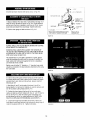
CRAFr.3
_xeRouter
Table
:CAUTION!_Read
AllInstructions
Carefully
(RouterNotIncluded)
Solday:
SEARS,ROEBUCK
AndCO.
3333 BeverlyRoad,
HoffmanEstates,IL 60179
Made In U,S.A.
i
i
Pa_
No.
49L
CN:59
Printed h7U,S.A.
FAILURETO HEEDALLSAFETYAND OPERATINGINSTRUCTIONS
ANDWARNINGSREGARDINGUSEOFTHIS PRODUCTCANRESULT
IN SERIOUS80DILY INJURY.
GENERAL
SAFETYINSTRUCTIONS
FORPOWERTOOLS
1. KNOWYOURPOWERTOOL
Readthe owner's manualcarefully.Learn its applicationand
limitationsas well asthe specific potential hazardspeculiarto this
toot.
2. GROUNDALLTOOLS(UNLESSDOUBLEINSULATED)
If tool is equippedwith an approved3-conductor cord and a 3prong grounding type plug, it should be plugged intoa threehole
electricalreceptacle,If adapteris usedto accommodatea twoprong receptacle,theadapterwire must be attachedto known
ground, (usuaflythe screw securing receptaclecover plate). Never
remove third prong.Neverconnectgreen ground wire to a
terminal.
3. KEEPGUARDSIN PLACE
12. USESAFETYGOGGLES(Head Protection)
WearSafetygoggles(mustcomplywith ANSI'Z87,1)at all times.
Also, use faceor dust mask, if cutting operationis dusty, and ear
protectors (plugs or muffs) during extendedperiodsof operation.
13. SECUREWORK
Useclamps or a vise to hold work when practical, It's saferthan
using your hands, and it frees both handsto operatetool,
14. DON'TOVERREACH
Keep proper footing and balanceat atf times.
i5. MAINTAINTOOLSWITH CARE
Keep tools sharp and cleanfor best and safest performance.
Follow instructions for lubricating and changingaccessories.
In working order,and in proper adjustment and alignment,
16. DISCONNECTTOOLS
4. REMOVEADJUSTINGKEYSANDWRENCHES
Before servicing, when changingaccessoriessuch as blades,bits,
cutters, etc.
Forma habit of checkingto seethat keys and adjusting wrenches
are removedfrom too! beforeturning it on.
5. KEEPWORKAREACLEAN
Clutteredareasand benchesinvite accidents,Floor must not be
17. AVOIDACCIDENTAL
STARTING
Make sure switch is in "OFF"position before pluggingin.
18. USERECOMMEND_ED
ACCESSORIES
slippery due to wax or sawdust.
Consult the owner's manualfor recommendedaccessoriesand
6. AVOIDDANGEROUS
ENVIRONMENT
follow the instructions, The use of improper accessoriesmay
causehazards.
Don't usepower tools in damp or wet locationsor exposetllem to
rain. Keepwork area wel! lighted: Provideadequatesurrounding
work space.
19. NEVERSTANDONTOOL
7. KEEPCHILDRENAWAY
All visitors should be kept a safe distancefrom work area.
8. MAKEWORKSHOPKID-PROOF
Usepadlocks,masterswitches, or remove starter keys.
9, DON'TFORCETOOLS
It wilt do the job betterand safer at the rate for which it was
designed,
10. USERIGHTTOOL
Don't force toot or attachmentto do a job it was not designedfor.
11. WEARRIGHTAPPAREL
Do not wear loose clothing,gloves, neckties or jewelry (rings,
wrist watches)to get caugt]t in moving parts, Nonslip footwear is
recommended,Wear protectivehair covering to contain long flair.
Roll long sleevesabovethe elbow.
Serious injury could occur if the tool is tippedor if the cutting tool
is accidenta!lycontacted. Do not store materials aboveor near the
tool making it necessaryto stand on the tool to reachthem.
20. CHECKDAMAGEDPARTS
Beforefurther use of the tool, any guard or other part that is
damagedshould be carefullycheckedto ensure that it will operate
properly and perform its intendedfunction. Checkfor alignment of
moving parts, binding of moving parts, breakageof parts,
mounting, and any other conditions that may affect its operation.A
guard or any other part that is damagedshould be properly
repairedor replaced.
21. DIRECTIONOF FEED
Feedwork into a bladeor cutter against the direction of rotation of
the bladeor cutter only.
22. NEVERLEAVETOOLRUNNINGUNATTENDED
Turn power off. Don't leavetool until it comes to a completestop,
ENERALSAFETYI
UCTI
THE
LEWITH UNITIZEDFENCE.
1. ALWAYSUSEEYEPROTECTION
Theoperationof any powertoo! can result in foreign objects being
throwninto the eyes,which can result in severeeyedamage.
Alwayswear safety goggles beforecommencing power tool
operation,Safetygoggles are availableat Searsretail or catalog
stores,
11. WHENENDCUTTINGONWORKPIECES'4"
WIDEOR LESS,
CLAMPAND HOLDAND FEEDTHE WORKPIECE
WITHTHE PUSH
BLOCKUSINGBOTHHANDS,AS SHOWNiN FIG. #23. KEEP
FINGERSCLEAROF BITWHENMOVINGWORKPIECE
ACROSS
THECUTTINGAREA.NEVERPLACEYOURHANDSLOWERTHAN
THETOPOFRETRACTABLE
GUARD.
2. KEEPHANDSCLEAROF BITSANDWORKINGAREA
12. ROUTERBITSARE_:_rREMELYSHARP.
3. MAKEANOUSEA PUSH STICKTOMOVESMALL
WORKPIECES
ACROSSTHE CUTTINGAREA.
Be extra careful when working around them.
4, KEEPROUTERCLEANAFTEREVERYUSE, CLEANSAW DUST
OFFTHEROUTER.
POSITION(SUCHAS ONA ROUTERTABLE),WILL FALL(OR
DROP)OUTOFTHE ROUTERBASEWHENTHEBASECLAMPIS
LOOSENED+
IT IS THEREFORE
ABSOLUTELY
NECESSARY
TO
SUPPORTTHEROUTERMOTORFROMBELOWWHENTHEBASE
CLAMPIS LOOSENED
TO MAKEADJUSTMENTS,OR FORANY
OTHERREASON.
5. YOURROUTERTABLEiS PROVIDEDWITH A DUST
COLLECTING
ATTACHMENTALWAYSUSESHOPVACFORALL
ROUTINGOPERATIONS
REQUIRINGUSEOF FRONTSIDE OF
UNITIZEDFENCE.(FRONTSiDEtS THESIDEWITH THE
CRAFTSMANLABEL).
NOTE:Motors usedon wood-working tools are particularly
susceptibleto the accumulation of sawdust and wood chips and
should be "vacuumed" frequently to prevent interferencewith
normal motor ventilation.
6. CHECKFUNCTIONOFGUARDBEFOREEACHUSE.REMOVE
ALLDUSTANDCHIPSFROMGUARDAREAASNEEDEDTO
MAINTAINGUARDFUNCTION.
7. NEVERPUT YOURFINGERSUNDERTHE GUARDWHENTHE
ROUTERIS PLUGGEDIN.
8, ALWAYSUSETHE ROUTERTABLEFENCETO GUIDETHE
WORK.DONOTWORKFREEHAND.
When using pilot type bits, keepthe fences as close to the pilot as
possibleto provideadditional backupand additionalguidanceand
to avoid chancesof an accidentand possiLllepersonalinjury, ,
9. ALWAYSFEEDAGAINSTTHEROTATIONOFTHECUTTER
WHENROUTINGON THEROUTERTABLE.FEEDWORKPIECES
IN
THEDIRECTIONOFTHEARROWAS SHOWNONTHE LABELON
THESIDEOFTHE FENCEBEINGUSED(WHENFACINGTHE
TABLEFRONT).
10. FORALLEDGECUTTINGANDENDCUTrlNGOPERATIONS,
USEFRONTSIDEOF UNITIZEDFENCE.USEBACKSIDE OF
FENCEONLYFORROUTINGOPERATIONS
AWAYFROMEDGEON
THEUNDERSIDEOFWORKPtECE
SUCHAS GROOVING,
FLUTING,VEINING,CROWNMOLDING,ETC.
13, SOMEROUTERS,WHENUSEDIN AN UPSIDEDOWN
t4. ALWAYSLOOKUNDERTHETABLEAT THESWITCHWHEN
TURNINGTHEROUTERON!OFFANDTOUCHNOTHINGBUTTHE
SWITCH, NEVERREACHUNDERTHETABLEWHENROUTERtS
RUNNINGFORANY OTHERREASON.
NOTE:It is far more safeand convenientto usea "Craftsman
+25183 Router TableSwitch package".This switch providesa key
operatedON/OFFbutton-which
1
allows fast and easy accesswhen
and if it becomesnecessaryto turn the router "OFF"quickly, The
key can be removed to render the switch inoperableto
unauthorizedpeople.
15. MOUNTROUTERTABLEFIRMLYAND SECURELY
TOA
WORKSURFACEBEFOREUSE.FAILURETO DOSO COULD
CAUSETABLETOTiP OVEROR SLIDEDURINGOPERATION
RESULTINGIN PROPERTYDAMAGEAND/ORSERIOUSBOOILY
INJURY.
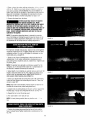
16.
BEFOREMAKINGANY CUT,UNPLUG
ROUTERAND RETRACTGUARDTO
MAKEABSOLUTELY
SURETHATRETRACTABLE
GUARDCLEARS
THE ROUTERBIT, ANDTHE GUARDIS FUNCTIONING
NORMALLY.SEEFIG. #16.
17.
WARNING:ROUTERVIBRATIONS
SOMETIMESCANCAUSEFASTENERS
FORTHETABLE,THE ROUTERANDTHEUNITIZEDFENCETO
GETLOOSErPERIODICALLY
CHECKFASTENERS
TOMAKESURE
THEYARETIGHTAND SECURE,
INTRODUCTION
How often haveyou neededa large guiding surfaceon a router table? Your CraftsmanRouter Tablewith UnitizedFencecomes with ttle
following:
• A unique 4" high unitizedfence designedto assist end grain
routing for makingtenons, sliding dovetailsand tongue and
groovejoints along with most edgeand face cutting operations.
• A speciallydesignedpush block with quick clamp for back up
and clamping boards up to 4"width for end grain routing.
• An accurateand quick adjustingjointing fence adjustableto
proper jointing depth of cut.
• Reversingfeature of unitized fence designedto enablerouting
operations like grooving, fluting, veining and crown molding etc.
up to 2_" away from the edge towards the mid,die of the board.
• Two guardsfor operationon either side of ihe unitized fence.
• Dust co!lecting attachmentfor most sllop vacuum hook ups,
• Extensionsthat providea large work surface.
If order to facilitate handlingand minimizeany damagethat might occur during shipment, your new router table is packaged
unassembled.We know you are anxiousto seewhat yOurnew too! wil! do, but a few minutes spent now carefullyreading the following
instructionswill result in less frustration and more enjoyableoperation later,
Start by checking and accountingfor all the loose parts, If any parts are missing, contact your local Craftsmanretail or hardwarestore
outlet for replacement.
OPTIONALROUTERTABLEACCESSORIES
#25326 CRAFTSMANUNIVERSALADAPTERPLATE,for mounting non-Craftsman1/4" shank routers to Craftsmanrouter accessories.
#25183 CRAFTSMANROUTERTABLEPOWERSWITCH,for turning router and other accessories"on" and "off" from the front of the
router table,
i
#25468 CRAFTSMANGUIDEMASTERRouterTablePush Shoe,aids in push shoe and hold down operations,accuratemeasurementand
router table setup,transforms into a miter gauge,and gives quick set up for 1/2" sliding dovetail joints.
#25489 CRAFTSMANROUTERTABLEFLOORSTAND,places router tables at convenientworking height, has adjustablefloor levelers,
and two steelshelvesfor storage,
UNPACKING
ANDCHECKING
CONTENTS
Refer to Parts List on Page 16
YOUMUST READANDUNDERSTAND
ALLTHEINSTRUCTIONSCOMPLETELY
BEFORE
ATTEMPTINGTO
ASSEMBLEANDOPERATE
YOUR ROUTER/ROUTER
TABLE,
TOOLSREQUIRED
, A small and medium size screwdriver.
• A small or medium size adjustablewrench,
• An electricalor hand drill with 1/8"drill bit,
• Hammer
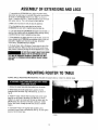
ASSEMBLYOF EXTENSIONSAND LEGS
t. Toassemblethe EXTENSIONS
and LEGSto ROUTERTABLE,
placetable, top side down, on a smooth, flat surfi_ce,and position
the LEGSand EXTENSIONS
relativeto the TABLEas shown in
Figure1. htsert the #10-32 x Yi' screwthrough the LEGand install
lock washer and nut. This is to be done for eachtable leg.
2, Makesure all screws and nuts are securelytightened,
3. Turnthe tabletop side up and checkto see that tfm
EXTENSIONS
are evenwith or slightly belowthe table top.
4, In no caseshould the EXTENSIONSbe higher thanthe table, or
elsethey may interfere with the workpieceduring routing causing
a condition that can result in possibleserious injury.
5. If the extensionsare higher than the top of the table, loosenthe
screws holding the EXTENSIONS
and reposition them so they art;
evenwith or slightly lower than the top of table, SECURELY
TIGHTENALL SCREWSAND NUTSAGAIN,
6. To double check, slide a flat pieceof wood along the top of the
tableboth directions, Make surethat the end of the wood moves
freely without contacting the edgeof the EXTENSIONnext to table,
DO NOTPLACEHEAVYOBJECTSOR PRESS
HEAVILYONTHE EXTENSIONSORELSE
THEYMAYBEDAMAGEDCAUSINGA CONDITIONTHATMAY
CANRESULTIN POSSIBLESERIOUS80DtLY INJURYDURING
ROUTING.
FIGURE 1
MOUNTINGROUTERTO TABLE
ALWAYSUNPLUGROUTERBEFOREMOUNTING(The tablewill acceptCraftsman3 hole 6 in. diameter base).
, i:f
1. Removethe router baseplate(back plate)from the router. '
2. While holding the router upsidedown, position it to the
undersidewithin the center ring of the table top, as shown in
Fig.#2,
3. Rotatethe router until the three mounting holes in the router
baseline up with threeof the holes in the table top (It will be
helpfulif you orient the router such that you can easily reach the
ON/OFFswitch from the front of the table. Craftsman_-25183
Router TableSwitch Packageprovideseasy access to ON/OFF
button).
4. Insert three #!0-32 x _" long flat head machine screws
(provided) through holes in the tabletop (See Fig, #2) and tighten
securelyinto the router base.
FIGURE2
5
•
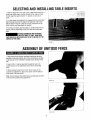
SELECTINGAND INSTALLING[ABLEINSERTS
1.With the desiredbit in the router, selecta table insert which has a
center hole slightly larger thanthe diameter of the router [)it. Note:
Forbits larger than approximately!_;" diameter,do not usean
insert,
2, Thetable insertsare designedto be snappedinto the router table.
Stidethe large tang under the edgeof the large hole in the router
tableas shown in Fig. #3. Using your thumb, press down on the
insert until the small tang snaps into position
3, Toremove the insert, placethe blade of a small screwdriver into
the slot (with the small tang) and pry the insert out of [he router
table.
BEFORE
ASSEMBLINGANDATTACHING
UNITIZEDFENCETOTABLE,MAKESURE
THATROUTERIS UNPLUGGED
ANDTHEBIT IS BELOWTHETOP
SURFACEOFTHETABLE.
HGURE 3
ASSEMBLYOFUNITIZEDFENCE
1, Slidejointing fencethrough rectangularopening in the cavity
providedon the unitizedfence(ribs on the unitizedfence will slide
in the grooves on the undersideof jointing fence). SeeFig. #4a &
#4b.
2, Insert ;./.-20x t" tong hex head bolt through the hole in the
unitizedfence (from the underside)and the slot in the jointing
fence,
3. While holding the headof the bolt in the hex recesson the
undersideof unitized [ence,placea flat washer over the bolt and
screwsmall _-20 knob on bolt.
Whenknob is loosened,the jointing fence canslide back and forth
in the cavity for proper iointing adjustment.
FIGURe."
4a
FIGURE4b
6
1. Placethe unitizedfence upsidedown on a flat surface as shown
in Fig. #5a & #Sb.
2. Orient the retractableguard as shown in Fig, #5a & #5b.
Positionand hold the spring over its hub such that formed end of
spring wraps over the guard as shown in Fig. #So & #5b.
3. While holding the spring overthe hub, and formed end over the
guard, position and press the straight leg of spring against surface
'X' to align hole in hub over boss on unitizedfence (see Fig. #5a &
#5b). Slip the guard over the boss, Spring wil! now be trapped
betweenthe guard and the fence.(Spring diameter is bigger than
the hub diameter.You will need to use both handsto hold spring
in proper position,).
4, Tightly secure retractableguard in placeusing set! threading #810 x _" long pan head ptasformscrew and a flat washer as shown
in Fig. #5a & #5b,
f.'K._URE
5a
5, Swing guard a few times in the direction of arrow to see that it
retractsout freely by itself and returns to its normal position over
the routertable hole. See Fig.#5a & #5b.
NOTE:If the guard does not retractout freely, loosenscrew just
enough until it does retract out freely and snaps back to normal
forward position by itself,
6. Turn the unitizedfence right side up.
FIGURE5b
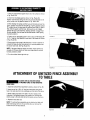
ATTACHMENT
OFUNITIZEDFENCEASSEMBLY
TOTABLE
ALWAYSUNPLUGROUTERBEFORE
ATTACHING
FENCETOAND REMOVING
FROMTABLE.
1. Assembleunitized fenceassemblyto table as shown in Fig. #6.
2. Insert one of the _-20 x 1_" long hex head bolts through the
hole in the tabletop (from the underside)and the slot in the fence.
3. While holding the head of the bolt in the hex recesson the
undersideof the tabletop,placea flat washer over the bolt and
install a large '_-20 knob onto the bolt to loosely secure the fen_:e.
4, Repeatfor tile other slot,
NOTE:The unitized fenceassemblycan be attachedto bible with
either sidefacing the front, Touse other side, just remove the
knobs and turn the fencearound.
RGURE6
7
i
!, Screw the small end of clamp rod into threadedhole m clamp
ptateuntil the platebottoms on its shoulder (make sure clamp
plate is orientedsuch that letter "C" is facing outwardsas shown
in Fig,//7).
'FLAT WASHER
2. Tightlysecure clamp plateto clamp rod using _" helical lock
washerand a hex nut.
" PUSH BLOCK
3, Insert the opposite threadedend of clamp rod through hole in
pushblock, and install a flat washer and a wing nut on to it.
ROUTERVIBRATIONS
SOMETIMESCAN
CAUSE1/4-28 HEXNUTANO CLAMP
PLATETOGETLOOSEtPERIODICALLY
CHECKFASTENERS
AND
CLAMPPLATETO MAKESURETHEYARETIGHTANDSECURE.
,
NUT
i[ CLAMP PLATERGURE F
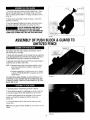
ASSEMBLY
OF
BLOCK& GUARDTO
UNITIZED
Clampplate, whenfree, tries to swing in the direction of arrow
(SeeFig. #8) due to its weight.
t. Mount push block assembly on the unitized fence by supporting
clamp plateagainst the face of the fence and aligning retaining rib
on push block with the groove in the face of unitized fence,
2. Slide push block assembly back and forth along entire length of
unitizedfence to seethat it slides freely.
NOTE:a, Removedust and chips from sliding surfaces of push
block and unitized fenceas neededto maintain good
sliding motion.
b, Occasionalapplicationof furniture spray wax on sliding
surfaces of PUSHBLOCKONLYwilt greatly in]prove the
sliding motion,
FIGURE8
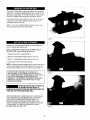
FORROUTINGON ENDS(TENONS,SLIDINGDOVETAILS,ETC,)
WORKPIECEIS HELDAGAINSTFACEOFUNITIZEDFENCEAND
CLAMPEDBETWEENCLAMP PLATEAND SURFACE'S'OFPUSH
BLOCK.SEEFIG.#8.
1. Assembleguard to unitizedfence as shown in Fig, #9,
2. While holding the guard at a slight angle,as shown, insert tab
on one side of guard into the hole inside the slot on the fence.
3, Hold the guard against this slot, straighten it into a vertical
position,and insert the opposite tab into the mating slot.
SeeFig, #9.
4, Pivot guard back and forth a few times to make sure that it
movesfreely.
NOTE:Oncethe guard has been installed,do nol remove it for any
reason,
FIGURE
9
8
THEROUTERTABLEMUSTALWAYSBEFIRMLYAND SECURELY
MOUNTEDTOA WORK SURFACEBEFOREUSE. FAILURETO DO
SO COULDCAUSETABLETOTIP OVERORSLIDE,RESUL.TING
IN
PROPERTYDAMAGEANDIORSERIOUSPERSONA[.INJURY,
Eachleg has (4} lloles at the bottom for mounting. Firmly secure
router table to work surface usingappropriate fasteneis (not
provided)as shown in Fig, #10.
Attach 1"x 6"or 2" x 6"skids to bottom of legs as shown in Fig.
#10. then securetable firmly to work surface.
FIGUREI0
Unitizedfence is providedwith a hookup for most Craftsman2_"
and 1¼"hose diameterwet!drj vats.
FORALL OPERATIONSREQUIRINGUSEOFFRONT-SIDEOF
UNITIZEDFENCE,connectwet/dry vac as follows:
1. Raiseguard and lean it againstthe fence,
2. Attach2_" hosediameter nozzleas shown in Fig.#'! 1.
3. Attach 17" hosediameter nozzleas shown in Fig. #12,
4. Lowerguard and let it rest on the vac hose.
NOTE'.Formaximum suction efficiency,stick a pieceof tape or use
a pieceOfscrap wood to cover up the opening in the rear of the
fence as shown in Figures1! and 12. Uncoveropening after use,
FOROPERATIONSREQUIRINGUSEOFBACKSIDEOF
UNITIZEDFENCE,DONOTCONNECTWET/DRYVACAS IT
WILL HINDEROPERATION,
THEBACKSIDEOFFENCE1SONLY
FORCUTTINGOPERATIONS
ONTHE UNDERSIDEOF
WORKPIECETHE WORKPIECEDURINGSUCHOPERATIONS
COMPLETELY
COVERSTHEROUTERBIT AND THEDUST
CANNOTBE VACUUMED.
FIGURE11
OPERATING
ROUTERTABLEWITHOUTUSE
OFWET/DRYVACMAYRESULTtN
EXCESSIVE
COLLECTION
OFSAWDUSTAND CHIPSUNDERTHE
FENCEANDTHE RETRACTABLE
GUARDAREA,
FORYOUROWNSAFETY,ALWAYSUNPLUGTHE ROUTERAND
CHECKFUNCTIONOFGUARDBEFOREEACHUSE REMOVE
DUSTAND CHIPSFROMGUARDAREAAS NEEDEDTO
MAINTAINGUARDFUNCTION,KEEPWORK AREACLEAN.
REMOVEUNITIZEDFENCEFROMTABLE(MAKESUREROUFEr_
tS UNPLUGGED)TO CLEAROUSTAND CHIPSTRAPPED
BElWEENFENCEANDTABLETOE
FIGURE 12
9
Assembleprotractor headtOmiter bar as shown in Fig. #13.
,_"
1. Measuredistancefrom each end of unitized fence to edge 'E' of
miter bar slot on thetable as shown in Fig. #t4. If both distances
are the same,the fence is parallelto miter bar sfot. !t not, loosen
largeknobs and adjust fenceaccordingly,Tighten both knobs.
__"t¢"*......._
.. _4-417X 3/4 LG
PANHEAD
MACHINE SCREW
-_--
POtNTER
/
2. Position miter gaugeon tableas shown in Fig #14.
3,'t6'f'ALNUT...............
PALNU_ TOBE PU,S'HEO
ONTO STUD UNTIL
tT BOTTOMSOUT AGAINSTMtTER BAR
FIGURE13
ALWAYSUNPLUGTHE ROUTERBEFOREMAKINGANY SETTING,
ADJUSTMENTSORCHANGINGBITS,
WHENROUTING,ALWAYSFEEDAGAINSTTHE ROTATIONOF
THE CUFrER FEEDWORKPIECEIN THE DIRECTIONOFARROW
AS SHOWNONTHE LABELONTHESIDE OFTHE FENCEBEING
USED(when facing the table front).
Theunitized fenceon your table is providedas a guide, against
which the workpieceshould be heldfor accuracy in routing. Free
hand routing (not holding work against the fence) is hazardous
and should be strictly avoided.
Wet/dry vac with eitller 2S" diameteror 1/" diameter hose nozzle
should be connectedto the dust collectionattachmentwhen using
the router table,
FIGUREt4
tn order to retractthe guard and haveful! access to the router bit
for making adjustments,select a board that is smooth with edges
and endstrue to eachother and its surfaces,Keepin mind the
foi!owing as wel!:
1. Mark lines 'A and 'B' on the end of this board. Line 'A' for
desireddepth of cut (amount of material you want Io remove)and
line 'B' for desiredcutting heighL SeeFig. #I 5,
2. Position this board against theface of tile fencewith edge
resting on tabletop and end marked with lines 'A' and 'B' dose to
the bit. SeeFig, #t5. (This will retractguard inside tenceand
provideaccessto the bit for making adjustments, MAKESURE
ROUTERtS UNPLUGGED
WHENMAKINGADJUSTMENTS.)
3, Loosen both large knobs that allow movement of fence and
move fence forward and backwarduntil outermost cutting edge ef
router bit is alignedwith line 'A'. Tighten both knobs.
FfGUREt5
t0
\,
#t0-32 x 3,;4" LG.
CARRtAGEBOLT
HEX
4. Raiseor lower the _outeruntil top cutting edg(_cf bd _,._
_f!:(m,}d
with line 'B. (Refer to your router ownel's !rla,llual hji' adjusliq_ I
your router proper}y).AFTERMAKINGTHISAOJUS:rMENT,i-3E:
SURETHATROUTERIS SECURELY
TIGHTENEDtN ]HE ROUTER
BASE,BIT tS SECURELY
TIGHTENEDIN THEROUTEF_
CHUCK,
AND ROUTERBASEIS 1tGHTLYSECUREDTO TABLETOK
5, Removethe board flora the fence,
WHENADJUSTINGHEIGHTOF ROUTER
BITFORANYDESIREDCUT,MAKE
ABSOLUTELY
CERTAINTHATTOPOF BITIS BELOWTHE INSIDE
SURFACEOFRETRACTABLE
GUARD,ASSHOWNIN FIG. #16,
CHECKTO SEETHATGUARDRETRACTSFREELYIN ANDOUT OF
FENCETOITS NORMALPOSITIONOVERTHE ROUTERTABLE
HOLE, DONOTOPERATE
ROUTERIF ANYPARTOFTHE BIT
CONTACTS
THE GUARD.
NOTE:The proceduredescribedaboveis intendedto provide a
way of retractingand holdingthe guard to havefull accessto the
_outerbit for making adjustment& Workpieceto be routed could
be substituted for the scrap boardfor making adjustmertts.
fIGUREt6
For maximum strength and accuracy,boards to be joined together
should be smooth and true. Theedgesshould be true to the (90°)
workpiecesurface, You cantrue the edgesof workpieceon your
router table using a straight bit.
!, Checkto see if face of jointing fence is flush with the face of
unitizedfence, If not, loosensmall knob on jointing fence and
push jointing fence inside the cavity in unitized fence.Tighten knob
on jointiag fence.
NOTE:The jointing fence provides a continuous support for the
workpiece,as it is fed beyondthe router bit, tt compensatesfor
the amount of material removedby the router bit,
2. Adjust depth of cut (material you want to remove) and router bit
l]eight as describedbeforefor Fig,#!5, Tightly secure the fence
and the router as described before.(MAKESUREROUTERIS
UNPLUGGEDWHENMAKINGADJUSTMENTS.)
FIGURE17
3. Checkyour adjustmentsby turning the router 'ON' and feeding
a pieceof scrap wood a few inches beyondrouter b_t.Thenstop
and turn router 'OFF',
NOTE:Feedwork in the direction of arrow shown on label on the
frontside of unitized fence (whenfacing table front).
4, Loosenknob on jointing fence and move it out flush against i:l]e
finished edge of scrap wood, Retightenthe knob See Fig _17.
5. Repealthe test cut on the scrap wood.
6. Therouter table is now readyfor use,
NOTE:For best jointing results, take very shallow cuts _--/;:,"or
less.
RGURE t8
1. Position the jointing fence such that its face is flush with the
face of unitized fence.Tighten small knob on jointing fence.See
Fig,#! 8,
11
2_Adjusl
depthof(;ut
(material
youwanttoremove)
and router
bit
Ileight as d_,scribedbefore. Tightenboth large knobs to lock fence
on table. Tightly securethe router,(MAKE SUREROUTERtS
UNPLUGGEDWHENMAKINGADJUSTMENTS,)
3. Testcut a piece of scrap wood to make sure your adjuslments
are satisfactory.
NOTE:Feedwork in the direction of arrow shown on label on
frontside of unitizedfence (when facing tablefront),
4, The router table is now readyfor use,
Rememberthe following when bits with pilots are usedto control
the cutting depth:
1. Position the jointing fence in the same manner as with nonpiloted bits.
FIGURE_19
2, Move the unitized fence back only enough to permit the pilot to
control the cutting depth. Positioningthe unitized fence as close to
the pilot as possible will serve as a back-up and will help in
avoidingan accidentand possiblepersonalinjury, See Fig. #!9.
NOTE:if you havepurchasedRAILAND STILECUTFERS
(Craftsman-_21257 or _21259) for making cabinet door frames on
your router table, MAKESURETHATFRAMETHICKNESSis not
more than _". II frame thicknessis more than _", the top of i[f_ebit,
as shown in Fig. 20, will interferewith retractableguard on your
unitizedfence, SeeFig. #20 and Fig. #16,
THAN3/4"
FIGURE20
When routing on endsof workpiecefor making tenons,sliding
dovetailsand tongue and groove joints, the workpiecemust be
madesmooth with both edgesand ends madetrue to eachother
and its surfaces. (90°)
NOTE:Thepush block and clamp plate assemblywilt not
accommodateworkpiecewider than 4".
EXAMPLE:
CUTTINGTENONS
1. Make certain that jointing fence is locked in position with its
face flush with that of unitizedfence.
2. Mount push block assembly on unitizedfence as shown before
in Fig. #8.
FfGURE21
3. Install proper table insert into the table top hole,
4, Mark lines 'A' and 'B' on the edgeof the workpiece closest to
the end to be cut. Line 'A' for FULLDEPTHOFCUT (total amount
of materialyou want to remove) and line 'B' for FULLOEStRED
HEIGHTOFTENON.SeeFig. #2t.
12
[
DONOTSETDEPTHOF CUTMORETHAN
_" (FIG. #23). IF DEPTHOFCUTIS MORE
THAN %",THEEDGE'E' OFWORKPIECE
WHENSLIOtNG
ACROSSWILL INTERFERE
WITH PORTION'P' OFGUARD.THE
GUARDTHENWILL NOTRETRACTINSIDEFENCE,ANDYOU
WILL NOTBEABLETOSLIDEWORKPIECE
ACROSSTHEBIT TO
MAKETHE CUT,SEEFIG. #24.
• " ' "
3,"8' MAX. DEPTH
f
5. POsitionworkpiecebetweenclamp plate and push block such
that its side is held flush against face of the unitizedfence,el_(ito
be cut is resting on the edge of the table top hole and edge
marked with lines 'A' and 'B' is facing the router bit. Clamp
workpiecein this position by snugly tightening the wing nut on
clamp rod while making sure that clamp platestays orientedon
workpieceas shown in Fig.#21. (This will retract guard inside the
fence and provideaccessto the bit for making adjustments. MAKE
SUREROUTERIS UNPLUGGED
WHENPOSITIONINGAND
CLAMPINGWORKPIECE
AND MAKINGADJUSTMENTS)
NOTE:Tighten wing nut just enough to clamp workpiece in
position. OVERTIGHTENING
wing nut could cause binding in tim
sliding motion of push block, which in turn may result in variations
andlor steps in thefinished tenon surface when cut. SeeFig, #25.
,
3,'8"&'lAX.
DEPTH
o_-CUr
FIGURE22
6. Slide workpiececlose to the bit and adjust unitized fence and
the router as described before,so that outer-most cutting edge of
bit is alignedwith line 'A' and top cutting edge of bit is aligned with
line 'B'. See Fig,#21. Tightly secure the fence and the router, as
describedbefore in ADJUSTINGDEPTHAND HEIGHTOFCUT.
7. Slide push block and workpiece back to let guard swing out to
its normal position as shown in Fig. #14.
8. Turn router and wet/dry vac 'ON'. While holding push biock
GUIDEWORKPIECE
AGAINSTFENCEWITH BOTHHANDS(Fig.
#23 & #24) and FINGERSATSAFEDISTANCEABOVEGUARD
AND SPINNINGBIT.Feedworkpieceacross the bit to make FULL
DEPTHOFCUTtN ONEPASS(DONOTSTOPFEEDUNTIL
WORKPIECEIS FARENOUGHBEYONDSPINNINGBIT TOALLOW
GUARDTO RETRACTOUTFULLYTO ITS NORMALPOSITION).
NOTE:Clampand test cut a pieceof scrap wood Io ci:leckyour
adjustmentsbeforemaking your finished cut.
9. Turnrouter and wet/dry vac 'OFF'.Unclampworkpieceand slide
push block back,
HGURE 23
EDGE "E"
10. Position and clamp the opposite skJeof workpiece in tile same
manneras describedin Step #5 (make sure the wing nut is tight
just enoughto clamp workpiecein position and end to be cut is
resting on the edge of table top hole.} Repeatslops #7. #8, and
#9.
_ i¸ i
11, Tocut endsof the tenon, position and clamp workpiecein the
same manrmras in step #5 above,exceptedge of workpiece
should be hetdflush againstface of fence and end to be cut
should be resting on edge of table top hole, See Fig. #24, Repeat
steps#7, #8, #9, and #10.
#IGURE24
13
:'
¸¸
?
NOTE:When cutting tenons,alwaysclamp work[)ic(:_,_,_.Ati,
(:nd to
be cut resting on edgeof tabletop hote,1his will inmnuizeste_s m
finished tenor] surface (Fig.#25) due to w.triationsin lhe tabletop
flatness,
ALWAYSCUTFULLDEPTHON ALL4 SIDES
OFTENONIN ONEPASSACROSSTHE6IT,
ONCETHESIDESARECUTANDIF STEPSOROTHER
IMPERFECTIONS
ARENOTICEDON FINISHEDTENONSURFACE,
CLEANTHEMWITH WOO0CHISEL,SANDPAPERORFILE, ETC.
DONOTTRYTO CLEANTHEMBY RE-SETTING
WORKPIECEON
ROUTERTABLEAND FENCE,WORKPIECE
MAYINTERFERE
WITH GUARD(SEEFIG. #21) WHICHiN TURNWILL PREVENTIT
FROMSLIDINGACROSSTHEBIT.
STEPStN FINISHED
TENONSURFACE
FIGURE25
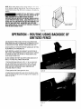
OPERATION ROUTINGUSINGBACKSIDE
OF
UNITIZEDFENCE
USEBACKSIDEOFFENCEONLYFORROUTINGOPERATIONS
AWAYFROMEDGEONTHE UNDERSIDEOFWORKPIECE,SUCH
AS GROOVING,FLUTING,VEINING,CROWNMOLDING,ETC,
ALWAYSUNPLUGTHEROUTERBEFOREMAKINGANY SETTING,
ADJUSTMENTS,ORCHANGINGBITS.
WHENROUTING,ALWAYSFEEDAGAINSTTHEROTATIONOF
THECUTi'ER.FEEDWORKPtECEIN THE DIRECTIONOFARROW
AS SHOWNON LABELONTHE SIDEOFFENCEBEINGUSED
(when facing the table front),
DO NOTCONNECTWET/DRYVACWHENUSINGBACKSIDEOF
FENCE,THEHOSEWILL HINDEROPERATION.
t. Removeboth large knobs and k._-20x 1_" lg. hex head botts,
turn the unitizedfence around and attach it back to table with
backsideof fence facing the table front. See Fig. #26. (MAKE
SUREROUTERIS UNPLUGGEDWHENREMOVINGAND
ATTACHINGFENCETOTABLE).
2. Raiseguard and let it leanagainst,the fence.
FIGURE26
3. Position the fence behind the router bit for the desiredcutting.
depth (the distanceof the cut from the edge of the workpiece,as
shown in Fig. #27).
FIGURE27
14
4. S(;cureivllgh!(!n br}thkn(}b::_
and i i)WER ll-fi} f_lJ_&iq_:
_,_');.;_:t:_
THEBIT
5. Make,die cut fly sli(lmg,shai[,hi _,,_I!j-;_'
o! wo_kpiecea :lamStt!]e
fence.(For eachsucc_ssve cut, the fence would needto bc
readjtJsted.)
NOTE:Testcol a pieceof scrap wood before making yotir finish(!d
cut. Feedworkpiecein the direction d arrow shown on _er_c_
_,label
(Fig.//28).
NOTE:When routing deep cuts (conboiled by router bit) in a
workpie(,e,remove material in incrementsto prevent your router
from overloading.Repeatoperationwith severalpassesuntil the
desireddepth is achieved.
F!GLIR_28
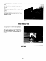
PROTRACTOR
Your protractorwill serveas a !landyaid when extrasupport is
neededfor routing small workpiecesor endsoi' largeworkpiec:e,s.
SeeFig.#29.
NOTE:FORALL ROUTINGOPERATIONS
REQUIRINGUSI!:OF
MITERGAUGEALONGWITH THEFENCE.BE SURETOALIGN
FENCEwrrH MITER BARSLOTBEFOREMAKINGANY CU]S
SEEFIG.#14,
FIGURE29
NOTES
15
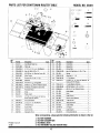
PARTSLIST FORCRAFTSMANROUTERTABLE
! -_ 4t
MODELNO. 25481
5.I .3_ 3,t7.28.31
_'_.._ ..... 36
'_,_h-
'
lb
{t[Lt&WaIIIiMB
25,4
29
t
27
40
t6
-';'i;'_
,/
30
J [
/
J
14 39
/
"
:__
/
29
Key
No.
PartNO,
Description
Quan,
Key
No,
!
31L-431
CastRouter TableTop
1
22
Parl No.
29L-648
Oescrtlltlon
PushBlock
2
29LCN-985
TableLeg_
4
23
3
4
F29A*306-41 Y_"O.D.x ?d' !O, x/,_" FiatWasher
'
F29A-489-10 Hex.Hd, Bolt ¼-2(Yx I:Y,
29L-65t
Ct_m£Rod
1
3
2
24
29L-652
C]am_Plate
t
25
F29A-246-20
Hex.Hd. CaPScrew¼- 20 x 1" Lg,
5
F29A-242-2
#10-32 Hex. Hd,MachineScrewNut
1
16
26
6
2gLeN-967
Miter Pointer
29L-654
Spring
1
1
27
28
F29A-252-16
F29A-306-40
Wing.Nut _" - ! 8 .......
W' FlatWasher
7
29L-183
1
1
8
29LCN-966
GroovedPinY¢ dia, x _"_LL_
Miter Bar
1
9
F29A-310-20
#!0-24 X ¾"Lg_CarnageBolt
t
29
F29A-970-5
#10-32 x 1/2" Lg. Truss Hd. Machine t6
Screwwith Phi!. Recess
tO
F29L-469-21
I1
F29L-242-15
#4-40 x ¾"Lfl, PanHd. MachineScrew !
#4-40 Hex.Hd. MachineScrewNut
1
30
31
F29A-327-5
F29A-306-26
_"-Lock Washer(He!ica!)
#8 FlatWasher¾_"IO. x _" 0.0.
t2
29L-293
ProtractorHead
' 1
32
F29A-653
#8-10 x _" Lg. PlasformScrew
1
33
34
29L-660
29L-659
Knob£La
r__
Knob
2
1
35
45A-382
Label(Fence)
1
36
29L-655
VacuumHoseReducer
1
16
37
F29A-242-16
_4-28HexNut
1
13
31L-560
Knob
1
14
29L-202
PlasticInsert
5
15
29LDo841-4
#!0-32 x _" FlatC'SunkHd. Machine
Screwwith Phil. Recess
3
Quan.
1
1
1
16
29A-509-1
#10 Lock Washer
17
29A-306-37
_" O,D.x _" I.O. FlatWasher
1
38
29L-610
TableExtensions
2
18
29L-645
UnitizedFence
I
19
29L-650
Guard(Red)
1
39
40
45A-383
29A-491*2
Label(Table_].
Y,"Palnut
1
!
20
29L-647
Guard(Small)
1
41
45A-292
49LCN-59
Label6___.ua
rd__
instruction Manual
1
1
2_ ...... 2__:6_9._
.......
AAdjustable
Fence
Whencorresponding,always givethefollowing informalionas shownin thelist.
Printed in U.S.A,
11/96
I]1111!11
1.
2.
3.
4.
The
The
The
The
PART NUMBER
PART DESCRIPTION
MODEL 25481
ITEM NAME-DELUXE ROUTER TABLE
........
16