1
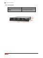
EP-2806-SA3
SCSI to SATA II
RAID Subsystem
User Manual
Revision 1.1
SCSI to SATA II RAID Subsystem
Preface
About this manual
This manual provides information regarding the quick installation and hardware
features of the EP-2806-SA3 RAID subsystem. This document also describes how
to use the storage management software. Information contained in the manual has
been reviewed for accuracy, but not for product warranty because of the various
environment/OS/settings. Information and specifications will be changed without
further notice.
This manual uses section numbering for every topic being discussed for easy and
convenient way of finding information in accordance with the user’s needs. The
following icons are being used for some details and information to be considered in
going through with this manual:
NOTES:
These are notes that contain useful information and tips
that the user must give attention to in going through with
the subsystem operation.
IMPORTANT!
These are the important information that the user must
remember.
WARNING!
These are the warnings that the user must follow to avoid
unnecessary errors and bodily injury during hardware and
software operation of the subsystem.
CAUTION:
These are the cautions that user must be aware of to
prevent damage to the equipment and its components.
Copyright
No part of this publication may be reproduced, stored in a retrieval system, or
transmitted in any form or by any means, electronic, mechanical, photocopying,
recording or otherwise, without the prior written consent.
Trademarks
All products and trade names used in this document are trademarks or registered
trademarks of their respective owners.
Changes
The material in this document is for information only and is subject to change without
notice.
2
User Manual
SCSI to SATA II RAID Subsystem
TABLE OF CONTENTS
Preface ........................................................................................................2
Before You Begin .........................................................................................6
Safety Guidelines .......................................................................................................................................................... 6
Controller Configuration............................................................................................................................................ 6
Packaging, Shipment and Delivery ....................................................................................................................... 6
Unpacking the Subsystem .............................................................................................................................. 7
Chapter 1 Product Introduction.................................................................8
1.1
Identifying Parts of the EP-2806-SA3........................................................................................................ 9
1.1.1
Front View ............................................................................................................................................... 9
1.1.2
Rear View ................................................................................................................................................. 9
1.2
Enclosure Chassis.............................................................................................................................................10
1.3
Technical Specifications.................................................................................................................................11
1.3.1 RAID Features........................................................................................................................................11
1.3.2
Enclosure ................................................................................................................................................11
1.3.3
Environmental ......................................................................................................................................12
Chapter 2 Physical Components ..............................................................13
2.1
2.2
2.3
2.4
2.5
Controller Module ...........................................................................................................................................13
2.1.1
Controller Module Panel .................................................................................................................13
2.1.2
Controller Module Installation ......................................................................................................15
2.1.3
Controller Board Replacement......................................................................................................16
Power Supply / Fan Module .......................................................................................................................18
2.2.1
PSFM Panel ...........................................................................................................................................18
2.2.2
Power Supply Module LED.............................................................................................................18
2.2.3
Fan of PSFM..........................................................................................................................................19
2.2.4
Power Supply Installation................................................................................................................20
2.2.5
Fan Replacement ................................................................................................................................22
Drive Carrier Module......................................................................................................................................24
2.3.1
Disk drive Indicators..........................................................................................................................24
2.3.2
Lock Indicator.......................................................................................................................................25
2.3.3
Disk Drive Installation .......................................................................................................................25
LCD Display Panel............................................................................................................................................27
2.4.1
LCD Display Panel LEDs ...................................................................................................................27
2.4.2
LCD Front Panel Function Keys ....................................................................................................28
Rackmount Slide Rail Installation..............................................................................................................29
Chapter 3 Getting Started with the Subsystem .......................................33
3.1
Connecting the RAID Subsystem to the Host .....................................................................................33
User Manual
3
SCSI to SATA II RAID Subsystem
Chapter 4 RAID Concepts ........................................................................34
4.1
RAID Fundamentals ........................................................................................................................................34
4.2
SCSI Concepts ...................................................................................................................................................39
4.3
4.2.1
Multiple SCSI Format Support ......................................................................................................39
4.2.2
Host SCSI ID Selection .....................................................................................................................39
4.2.3
Terminators ...........................................................................................................................................39
Disk Drive Organization ................................................................................................................................40
4.3.1
Physical Drive Groups .......................................................................................................................40
4.3.2
Logical Unit Number (LUNs)..........................................................................................................40
4.3.3
Hot-Swap Drive Replacement .......................................................................................................40
4.3.4
Disk Failure Detection.......................................................................................................................40
Chapter 5 Configuration Utility Options ..................................................41
5.1
Configuration through a Terminal............................................................................................................41
5.1.1
Upgrading Firmware through VT-100 Terminal Emulation...............................................46
5.2
Configuring the Subsystem Using the LCD Panel .............................................................................48
5.3
Configuration using the proRAID Manager GUI ................................................................................50
5.3.1
Login to proRAID Manager............................................................................................................50
5.3.2
The ProRAID Manager Main Menu.............................................................................................51
5.3.3
ProRAID Manager Menu Hierarchy.............................................................................................54
Chapter 6 RAID Management ..................................................................55
6.1
Quick Setup........................................................................................................................................................55
6.2
Create Array .......................................................................................................................................................58
6.3
Modify Array ......................................................................................................................................................61
6.4
Delete Array .......................................................................................................................................................62
6.5
Create Volume ..................................................................................................................................................63
6.6
Modify Volume .................................................................................................................................................66
6.7
Delete Volume ..................................................................................................................................................67
Chapter 7 Network Management.............................................................68
7.1
Network Settings .............................................................................................................................................68
7.2
SNMP Setting ....................................................................................................................................................69
7.3
SMTP Setting .....................................................................................................................................................70
7.4
NTP Setting ........................................................................................................................................................71
7.5
Sync RTC..............................................................................................................................................................72
Chapter 8 System Management...............................................................73
8.1
System Setting ..................................................................................................................................................73
8.2
Channel Manager ............................................................................................................................................75
8.3
Modify Password..............................................................................................................................................77
8.4
Upgrade Firmware...........................................................................................................................................78
8.5
Restart...................................................................................................................................................................80
4
User Manual
SCSI to SATA II RAID Subsystem
Chapter 9 Event Log ................................................................................81
9.1
Event Log ............................................................................................................................................................81
9.2
Export Log...........................................................................................................................................................82
Chapter 10 Information...........................................................................83
10.1
Disk Information ............................................................................................................................................83
10.2
RAID Information...........................................................................................................................................84
10.3
System Information ......................................................................................................................................85
10.4
Hardware Monitor.........................................................................................................................................86
Chapter 11 Raid Task...............................................................................87
11.1
Raid Status .......................................................................................................................................................87
Chapter 12 S.M.A.R.T. ..............................................................................89
12.1
Disk Health.......................................................................................................................................................89
12.2
Diagnosis Disk ................................................................................................................................................90
User Manual
5
SCSI to SATA II RAID Subsystem
Before You Begin
Before going through with this manual, you should read and focus on the following
safety guidelines. Notes about the subsystem’s controller configuration and the
product packaging and delivery are also included.
Safety Guidelines
To provide reasonable protection against any harm on the part of the user and to
obtain maximum performance, user is advised to be aware of the following safety
guidelines particularly in handling hardware components:
Upon receiving of the product:
Place the product in its proper location.
To avoid unnecessary dropping out, make sure that somebody is around for
immediate assistance.
It should be handled with care to avoid dropping that may cause damage to the
product. Always use the correct lifting procedures.
Upon installing of the product:
Ambient temperature is very important for the installation site. It must not
exceed 30°C. Due to seasonal climate changes; regulate the installation site
temperature making it not to exceed the allowed ambient temperature.
Before plugging-in any power cords, cables and connectors, make sure that the
power switches are turned off. Disconnect first any power connection if the power
supply module is being removed from the enclosure.
Outlets must be accessible to the equipment.
All external connections should be made using shielded cables and as much as
possible should not be performed by bare hand. Using anti-static hand gloves is
recommended.
In installing each component, secure all the mounting screws and locks. Make
sure that all screws are fully tightened. Follow correctly all the listed procedures
in this manual for reliable performance.
Controller Configuration
This RAID subsystem supports single controller configuration.
Packaging, Shipment and Delivery
Before removing the subsystem from the shipping carton, you should visually
inspect the physical condition of the shipping carton.
Unpack and verify that the contents of the shipping carton are complete and in
good condition.
Exterior damage to the shipping carton may indicate that the contents of the
carton are damaged.
If any damage is found, do not remove the components; contact the dealer where
you purchased the subsystem for further instructions.
6
User Manual
SCSI to SATA II RAID Subsystem
Unpacking the Subsystem
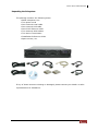
The package contains the following items:
• RAID subsystem unit
• Two power cords
• One external serial cable
• One external UPS cable
• One RJ-45 Ethernet cable
• Two external SCSI cables
• Two Active Terminators
• Installation Reference Guide
• Spare screws, etc.
If any of these items are missing or damaged, please contact your dealer or sales
representative for assistance.
User Manual
7
SCSI to SATA II RAID Subsystem
Chapter 1 Product Introduction
The EP-2806-SA3 RAID Subsystem
Features:
Intel 80331 64 bit I/O processor
Supports RAID levels 0, 1, 0+1, 3, 5, 6, 30, 50, NRAID and JBOD
Dual SCSI Ultra320 host channels support clustering technology
Instant availability and background initialization
Supports hot spare and automatic hot rebuild
Local audible event notification alarm
Real time drive activity and status indicators
Java based browser type GUI management utility
Supports password protection and UPS connection
Built-in Ethernet port interface for remote event notification
Transparent data protection for all popular operating systems
Supports multiple array enclosures per host connection
8
User Manual
SCSI to SATA II RAID Subsystem
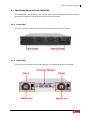
1.1 Identifying Parts of the EP-2806-SA3
The illustrations below identify the various parts of the subsystem. Each part will be
discussed in details in the following sections of this manual.
1.1.1 Front View
The front section consists of the Drive Carriers and the Smart LCD Panel.
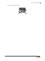
1.1.2 Rear View
The rear view consists of two Power Supply / Fan Modules and the Controller.
User Manual
9
SCSI to SATA II RAID Subsystem
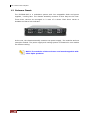
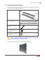
1.2 Enclosure Chassis
The EP-2806-SA3 is a redundant system with hot swappable disks and power
supplies / cooling fans. The chassis assembly contains 8 drive bays at the front.
These drive carriers are arranged in 2 rows of 4 drives. Each drive carrier is
lockable and has a lock indicator.
At the rear, the chassis assembly contains two power supply / fan modules and one
controller module. The power supply and cooling system is contained in one module
for efficient cooling.
NOTE: The modules of the enclosure are interchangeable with
other Epica products.
10
User Manual
SCSI to SATA II RAID Subsystem
1.3 Technical Specifications
RAID Controller
U320 SCSI-to-SATA II
Host Bus Interface
Ultra 320 SCSI
Drive Bus Interface
SATA II
Data Transfer Rate
Up to 320MB/Sec
Cache Memory
256MB ~ 2GB ECC DDR SDRAM
RAID Processor
Intel 80331 64 bit RISC
Remote Management
R-Link Port
Monitor Port
RS232
1.3.1 RAID Features
RAID Roaming
0, 1, 0+1, 3, 5, 6, 30, 50, Linear
and JBOD
Yes
Host Independent
Yes
Continuous Rebuild
Yes
Online Consistency Check
Yes
Failed Drive Auto Rebuild
Yes
Password Protection
Yes
Bad Block Auto-remapping
Yes
Hard Contact Relay Connection
Yes
SMTP Manager and SNMP Agent
Yes
RAID Level
1.3.2 Enclosure
Form Factor
2U 19-inch Rackmount Chassis
Failed Drive Indicators
Yes
Backplane Board
SATA II
Audible Alarm
Yes
Hot-swap Drive Trays
Eight (8) 1-inch trays
Two (2) 300W Power Supplies with
PFC
2
Hot-Swappable Power Supplies
Cooling Fans
UPS Connection
Environment Monitor
Power Requirements
Yes
Monitor Temperature, Fan, Power
Supply and Voltage
AC 90V~264V Full Range
6A ~ 3A, 47Hz ~ 63Hz
User Manual
11
SCSI to SATA II RAID Subsystem
1.3.3 Environmental
12
Relative Humidity
10% ~ 85% Non-condensing
Operating Temperature
10°C ~ 40°C (50°F ~ 104°F)
Weight
14 kg/30.8Lbs (without drives)
Physical Dimensions
88(H) x 482(W) x 460 (D) mm
User Manual
SCSI to SATA II RAID Subsystem
Chapter 2 Physical Components
2.1 Controller Module
The EP-2806-SA3 includes a U320 SCSI-to-SATA II Controller Module.
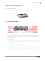
2.1.1 Controller Module Panel
The Controller Module has 6 major parts: Host Channel, UPS Port, RS-232 Port,
Ethernet Port, Alarm Mute Button, and a Hard Contact Relay. These parts are
described as follows:
1. Host Channel
The subsystem is equipped with 2 host channels (Host channel A and Host
channel B), with two 68-pin SCSI connectors at the rear of the subsystem, for
SCSI in and out.
2. Uninterrupted Power Supply (UPS) Port
The subsystem may come with an optional UPS port allowing you to connect a
UPS device. Connect the cable from the UPS device to the UPS port located at
the rear of the subsystem. This will automatically allow the subsystem to use
the functions and features of the UPS.
User Manual
13
SCSI to SATA II RAID Subsystem
3. RS-232 Port
The subsystem is equipped with a serial monitor port allowing you to connect to
a PC or terminal.
Below are the RS-232 settings.
Settings
Baud Rate
115200
Data Bits
8
Parity
None
Stop Bits
1
Flow Control
None
4. R-Link Port : Remote Link through RJ-45 Ethernet for remote
management
The subsystem is equipped with one 10/100 Ethernet RJ45 LAN port. You can
use Java-based browser to manage the RAID subsystem through Ethernet for
remote configuration and monitoring.
Link LED: Green LED indicates Ethernet is linking.
Access LED: The LED will blink orange when the 100Mbps Ethernet is being
accessed.
5. Alarm Mute Button
When the audible alarm is sounding, press this button to mute the audible
alarm.
6. Hard Contact Relay
14
User Manual
SCSI to SATA II RAID Subsystem
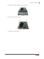
2.1.2 Controller Module Installation
In this section, you will be shown how to install the Controller Module.
a. Check for damage, especially to the connectors at the rear of the Controller
Module.
CAUTION! Handle the module with care and avoid damaging the
connectors. Do not install the module if the connectors are
damaged.
b. With the Controller handle in the open position, carefully insert the module into
the enclosure.
c. Manually close the handle to complete the Controller Module installation.
d. Tighten the thumb screws on the handle to secure the Controller Module to the
enclosure.
User Manual
15
SCSI to SATA II RAID Subsystem
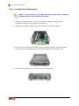
2.1.3 Controller Board Replacement
NOTE: It is necessary to use ESD anti-static device when handling
sensitive parts of the controller module.
1. Loosen the thumb screws. Raise the controller handle and pull out the
controller module until it moves out of the slot.
2. Release the memory module lock and remove the memory module.
3. Remove four screws at the bottom of the controller module. Note that there
are four hex screws supporting the controller board to the module case.
4. Remove the eight (8) lock nut screws at the front panel.
16
User Manual
SCSI to SATA II RAID Subsystem
5. Remove the controller board from the module case.
6. Remove the four hex nut screws.
7. Replace the controller board.
User Manual
17
SCSI to SATA II RAID Subsystem
2.2 Power Supply / Fan Module
Every EP-2806-SA3 contains two 300W Power Supply / Fan Modules. All
PSFMs are inserted into the rear of the chassis.
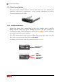
2.2.1 PSFM Panel
At the panel of the Power Supply/Fan Module, there are three distinct features: the
Power On/Off Switch, the AC Inlet Plug, and a Power On/Fail Indicator showing the
Power Status LED, indicating ready or fail.
Each fan within a PSFM is powered independently of the power supply within the
same PSFM. So if the power supply of a PSFM fails, the fan associated with that
PSFM will continue to operate and cool the enclosure.
2.2.2 Power Supply Module LED
When the power cord connected from main power source is inserted to the AC
Power Inlet, the power status LED becomes RED. When the switch of the PSFM is
turned on, the LED will turn GREEN. When the Power On/Fail LED is GREEN, the
PSFM is functioning normally.
18
User Manual
SCSI to SATA II RAID Subsystem
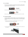
2.2.3 Fan of PSFM
Each PSFM has 1 Master Fan.
The Master Fan is located beside the PSFM panel.
Master Fan
NOTE: In the LCD display, Master Fan of Power Supply Unit A is shown as
“MF/PSU-A. Master Fan of Power Supply Unit B is “MF/PSU-B”.
User Manual
19
SCSI to SATA II RAID Subsystem
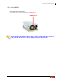
2.2.4 Power Supply Installation
This section describes how to install the Power Supply.
a. Check for damage, especially to the PCB Golden Fingers at the rear of the
Power Supply.
CAUTION! Handle the module with care and avoid damaging the
Golden Fingers. In addition, make sure there are no fingerprints on
the Golden Fingers. Do not install the module if the Golden Fingers
are damaged.
b. With the Power Supply handle in the open position, carefully insert the module
into the enclosure.
CAUTION! When inserting the PSFM, make sure the PSFM position
is correct (the handle is in the lower part when closed).
20
User Manual
SCSI to SATA II RAID Subsystem
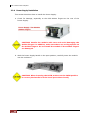
c.
Manually close the Power Supply handle.
IMPORTANT! To secure the Power Supply to the enclosure, tighten
the thumb screws.
d.
Connect the Power Supply cord from the power source to the AC Power Inlet.
IMPORTANT! For safety reasons, make sure the power switches
are turned off when you plug-in the power cords. When
removing the power cords, ensure that the switch on the back of
each power supply fan module are turned off and the power
on/fail LED are red.
User Manual
21
SCSI to SATA II RAID Subsystem
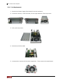
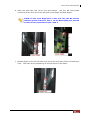
2.2.5 Fan Replacement
1. Remove the Power Supply Fan Module from the enclosure.
2. Unscrew 6 screws; 2 from left side, 2 from right side and 2 from top cover.
3. Pull up the top cover.
4. Disconnect the fan cable.
5. Unscrew the 4 screws of the power supply fan. Then remove the metal brace.
22
User Manual
SCSI to SATA II RAID Subsystem
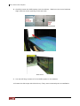
6. Remove the fan and replace.
User Manual
23
SCSI to SATA II RAID Subsystem
2.3 Drive Carrier Module
The Drive Carrier Module houses a 3.5 inch hard disk drive. It is designed for
maximum airflow and incorporates a carrier locking mechanism to prevent
unauthorized access to the HDD.
2.3.1 Disk drive Indicators
Every Drive Carrier has 2 status indicator lights. One indicator light is used for
Power On/Error. When this light is GREEN the power is on and everything is
functioning normally. When the Power On/Error light is ORANGE, then an error has
occur that requires the user’s attention.
The other status indicator light is the hard disk drive access light. When the hard
disk drive is being accessed, this light will flash BLUE.
In addition, both indicator lights are viewable within a 170° arc.
Status Light
Indicator
Disk
Activity
Indicator
Disk Status
Indicator
24
User Manual
SCSI to SATA II RAID Subsystem
2.3.2 Lock Indicator
Every Drive Carrier is lockable and is fitted with a lock indicator to indicate whether
or not the carrier is locked into the chassis or not. Each carrier is also fitted with an
ergonomic handle for easy carrier removal.
Drive Carrier
is Unlocked
When the Lock Groove is vertical, then the Drive Carrier is unlocked.
Drive
Carrier is
locked
When the Lock Groove is horizontal, this indicates that the Drive Carrier is locked.
2.3.3 Disk Drive Installation
This section describes the physical locations of the hard drives supported by the
subsystem and give instructions on installing a hard drive. The subsystem supports
hot-swapping allowing you to install or replace a hard drive while the subsystem is
running.
a. Make sure the Lock Groove is in unlocked position. Press the carrier open
button and the Drive Carrier handle will flip open.
Carrier
Open
Button
b. Pull out an empty disk tray. Pull the handle outwards to remove the carrier from
the enclosure.
User Manual
25
SCSI to SATA II RAID Subsystem
c. Place the hard drive in the disk tray. Make sure the holes of the disk tray align
with the holes of the hard drive.
d. Install the mounting screws on the bottom part to secure the drive in the disk
tray.
e. Slide the tray into a slot until it reaches a full stop.
f.
26
Press the lever in until you hear the latch click into place. The HDD status LED
will turn green on the front panel if the subsystem is on.
User Manual
SCSI to SATA II RAID Subsystem
2.4 LCD Display Panel
The LCD Display Panel is located at the upper right side of the system.
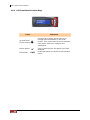
2.4.1 LCD Display Panel LEDs
Environmental Status
Parts
Function
Power LED
Green indicates power is ON.
Power Fail LED
If one of the redundant power supply unit
fail, this LED will turn to RED and alarm will
sound.
Fan Fail LED
Turns RED when a fan’s speed is lower than
2000 RPM or fan fails.
Over Temperature LED
If system temperature is over 70oC or disk
temperatures exceed 55oC the temperature
LED will turn RED and alarm will sound.
Voltage Warning LED
This LED will turn RED and an alarm will
sound if detected voltage in the controller is
abnormal.
Access LED
This LED will blink blue when the RAID
controller is busy / active.
User Manual
27
SCSI to SATA II RAID Subsystem
2.4.2 LCD Front Panel Function Keys
Parts
Functions
Use the Up or Down arrow keys to go
through the information on the LCD
screen. This is also used to move between
each menu when you configure the
subsystem.
Up and Down
Arrow buttons
Select button
Exit button
28
User Manual
EXIT
This is used to enter the option you have
selected.
Press this button to return to the previous
menu.
SCSI to SATA II RAID Subsystem
2.5 Rackmount Slide Rail Installation
An optional Rail box can be purchased and included in the shipping package. Verify
if the content of the Rail Box is complete.
2 x Rack Rails
2 x Inner Brackets
4 x M5*P0.8 L=25mm Long
Screws
8 x M5*0.8 L=8.0mm Round
Head Screws
12 x M4*0.7 L=6.0mm Flat
Head Screws
NOTE: To lighten the weight of the RAID system, remove the disk
trays with disk drives from the chassis.
1. Remove one screw (lower part) from the RAID system ear.
User Manual
29
SCSI to SATA II RAID Subsystem
2. Place one inner bracket to the side of the chassis. Align the holes on the front
side of the inner rail to the holes on the RAID system ear. Tighten the screw
that was removed in Step1.
3. Use four M4 flat head screws to attach the inner bracket to one of the side.
Make sure the holes of the inner bracket are aligned to the holes on the side of
the RAID system.
4. Repeat Steps 1 to 3 for the other inner bracket on the left side.
5. Loosen eight M4 screws on each of the rack rails. Make the necessary
adjustment on the length of the rack rails to conform to the depth of the rack.
Then screw the M4 screws back to the rack rails.
30
User Manual
SCSI to SATA II RAID Subsystem
6. Place the right side rack rail on the rack cabinet. Use four M5 round head
screws to fix the rack rail to the rack post (Front Right and Rear Right).
NOTE: In the Front Right part of the rack rail, the M5 screws
must be placed in holes 1 and 3. In the Rear Right part, the M5
screws must be placed in holes 1 and 4.
7. Repeat Step 6 to fix the left side rack rail to the rack post (Front Left and Rear
Left). Take note of the positioning of the M5 screws in the holes.
User Manual
31
SCSI to SATA II RAID Subsystem
8. Carefully insert the RAID system into the cabinet. Make sure the inner brackets
align with the center opening of the rack rails.
Front View
Rear View
9. Use two M5 long screws to fix the RAID system in the cabinet.
10. Insert the disk trays with disk drives, if they were removed prior to installation.
32
User Manual
SCSI to SATA II RAID Subsystem
Chapter 3 Getting Started with the Subsystem
3.1 Connecting the RAID Subsystem to the Host
The subsystem supports Ultra 320 SCSI LVD interface which provides fast 320MB/S data
transfer rates using a 16-bit SCSI bus. Installation of the disk array is very similar to the
installation of a standard SCSI drive. The SCSI connector accepts the standard 68-pin
LVD SCSI connector used on most LVD SCSI devices. Refer to your system and/or SCSI
host adapter manual for additional installation procedures that may apply to your system
or host adapter.
1.
Connect the power cables to the AC Power inlets.
2.
Connect the Ethernet cable to the RAID subsystem’s Ethernet port.
3.
Connect the external serial cable to the controller’s RS-232 Port (phone jack type).
4.
Connect the other end of the external serial cable to the RS-232 Port (DB9 type) on
your host system.
5.
The package comes with two external SCSI cables. For every pair of host channel
SCSI connector at the rear of the subsystem, attach one end of the external SCSI
cable to one of the SCSI Host Channel connectors and the other end to the host
adapter’s external SCSI connector. (The host adapter is installed in your host
system.)
6.
Attach a SCSI terminator to the other SCSI Host Channel connector (Host Channel
Out port). Make sure to tighten the lock screws of the SCSI terminator.
7.
Connect the other host system using the other external SCSI cable if you want to
configure subsystem into multi-host attachment.
NOTE: When one or more SCSI devices are connected, the total
length of all cables (internal or external) must not exceed 3
meters (9.8 ft.) to ensure reliable operation.
IMPORTANT: For safety reasons, make sure the Disk Array and
Host Computer are turned off when you plug-in the SCSI cable.
User Manual
33
SCSI to SATA II RAID Subsystem
Chapter 4 RAID Concepts
4.1 RAID Fundamentals
The basic idea of RAID (Redundant Array of Independent Disks) is to combine multiple
inexpensive disk drives into an array of disk drives to obtain performance, capacity and
reliability that exceeds that of a single large drive. The array of drives appears to the
host computer as a single logical drive.
Five types of array architectures, RAID 1 through RAID 6, were originally defined; each
provides disk fault-tolerance with different compromises in features and performance. In
addition to these five redundant array architectures, it has become popular to refer to a
non-redundant array of disk drives as a RAID 0 arrays.
Disk Striping
Fundamental to RAID technology is striping. This is a method of combining multiple
drives into one logical storage unit. Striping partitions the storage space of each drive
into stripes, which can be as small as one sector (512 bytes) or as large as several
megabytes. These stripes are then interleaved in a rotating sequence, so that the
combined space is composed alternately of stripes from each drive. The specific type of
operating environment determines whether large or small stripes should be used.
Most operating systems today support concurrent disk I/O operations across multiple
drives. However, in order to maximize throughput for the disk subsystem, the I/O load
must be balanced across all the drives so that each drive can be kept busy as much as
possible. In a multiple drive system without striping, the disk I/O load is never perfectly
balanced. Some drives will contain data files that are frequently accessed and some
drives will rarely be accessed.
By striping the drives in the array with stripes large enough so that each record falls
entirely within one stripe, most records can be evenly distributed across all drives. This
keeps all drives in the array busy during heavy load situations. This situation allows all
drives to work concurrently on different I/O operations, and thus maximize the number
of simultaneous I/O operations that can be performed by the array.
34
User Manual
SCSI to SATA II RAID Subsystem
Definition of RAID Levels
RAID 0 is typically defined as a group of striped disk drives without parity or data
redundancy. RAID 0 arrays can be configured with large stripes for multi-user
environments or small stripes for single-user systems that access long sequential
records. RAID 0 arrays deliver the best data storage efficiency and performance of any
array type. The disadvantage is that if one drive in a RAID 0 array fails, the entire array
fails.
RAID 1, also known as disk mirroring, is simply a pair of disk drives that store duplicate
data but appear to the computer as a single drive. Although striping is not used within a
single mirrored drive pair, multiple RAID 1 arrays can be striped together to create a
single large array consisting of pairs of mirrored drives. All writes must go to both drives
of a mirrored pair so that the information on the drives is kept identical. However, each
individual drive can perform simultaneous, independent read operations. Mirroring thus
doubles the read performance of a single non-mirrored drive and while the write
performance is unchanged. RAID 1 delivers the best performance of any redundant array
type. In addition, there is less performance degradation during drive failure than in RAID
5 arrays.
User Manual
35
SCSI to SATA II RAID Subsystem
RAID 3 sector-stripes data across groups of drives, but one drive in the group is
dedicated to storing parity information. RAID 3 relies on the embedded ECC in each
sector for error detection. In the case of drive failure, data recovery is accomplished by
calculating the exclusive OR (XOR) of the information recorded on the remaining drives.
Records typically span all drives, which optimizes the disk transfer rate. Because each
I/O request accesses every drive in the array, RAID 3 arrays can satisfy only one I/O
request at a time. RAID 3 delivers the best performance for single-user, single-tasking
environments with long records. Synchronized-spindle drives are required for RAID 3
arrays in order to avoid performance degradation with short records. RAID 5 arrays with
small stripes can yield similar performance to RAID 3 arrays.
Under RAID 5 parity information is distributed across all the drives. Since there is no
dedicated parity drive, all drives contain data and read operations can be overlapped on
every drive in the array. Write operations will typically access one data drive and one
parity drive. However, because different records store their parity on different drives,
write operations can usually be overlapped.
Dual-level RAID achieves a balance between the increased data availability inherent in
RAID 1 and RAID 5 and the increased read performance inherent in disk striping (RAID
0). These arrays are sometimes referred to as RAID 0+1 or RAID 10 and RAID 0+5 or
RAID 50.
36
User Manual
SCSI to SATA II RAID Subsystem
RAID 6 is similar to RAID 5 in that data protection is achieved by writing parity
information to the physical drives in the array. With RAID 6, however, two sets of parity
data are used. These two sets are different, and each set occupies a capacity equivalent
to that of one of the constituent drives. The main advantage of RAID 6 is High data
availability – any two drives can fail without loss of critical data.
In summary:
RAID 0 is the fastest and most efficient array type but offers no fault-tolerance. RAID
0 requires a minimum of two drives.
RAID 1 is the best choice for performance-critical, fault-tolerant environments. RAID
1 is the only choice for fault-tolerance if no more than two drives are used.
RAID 3 can be used to speed up data transfer and provide fault-tolerance in singleuser environments that access long sequential records. However, RAID 3 does not
allow overlapping of multiple I/O operations and requires synchronized-spindle drives
to avoid performance degradation with short records. RAID 5 with a small stripe size
offers similar performance.
RAID 5 combines efficient, fault-tolerant data storage with good performance
characteristics. However, write performance and performance during drive failure is
slower than with RAID 1. Rebuild operations also require more time than with RAID 1
because parity information is also reconstructed. At least three drives are required
for RAID 5 arrays.
RAID 6 is essentially an extension of RAID level 5 which allows for additional fault
tolerance by using a second independent distributed parity scheme (two-dimensional
parity). Data is striped on a block level across a set of drives, just like in RAID 5, and
a second set of parity is calculated and written across all the drives; RAID 6 provides
for an extremely high data fault tolerance and can sustain multiple simultaneous
drive failures. It is a perfect solution for mission critical applications.
User Manual
37
SCSI to SATA II RAID Subsystem
RAID Management
The subsystem can implement several different levels of RAID technology. RAID levels
supported by the subsystem are shown below.
RAID
Description
Level
Min
Drives
Linear is similar to RAID 0 in that it combines the
capacity of all member drives. The data is written
linearly starting with the first disk drive. When first disk
drive becomes full, the next disk drive is used. There is
no data redundancy.
1
0
Block striping is provide, which yields higher
performance than with individual drives. There is no
redundancy.
2
1
Drives are paired and mirrored. All data is 100%
duplicated on an equivalent drive. Fully redundant.
2
3
Data is striped across several physical drives. Parity
protection is used for data redundancy.
3
5
Data is striped across several physical drives. Parity
protection is used for data redundancy.
3
6
Data is striped across several physical drives. Parity
protection is used for data redundancy. Requires N+2
drives to implement because of two-dimensional parity
scheme
4
0+1
Combination of RAID levels 0 and 1. This level provides
striping and redundancy through mirroring.
4
30
Combination of RAID levels 0 and 3. This level is best
implemented on two RAID 3 disk arrays with data
striped across both disk arrays.
6
50
RAID 50 provides the features of both RAID 0 and RAID
5. RAID 50 includes both parity and disk striping across
multiple drives. RAID 50 is best implemented on two
RAID 5 disk arrays with data striped across both disk
arrays.
6
Linear
38
User Manual
SCSI to SATA II RAID Subsystem
4.2 SCSI Concepts
Before configuring the subsystem, you must first understand some basic SCSI concepts
so that the subsystem and SCSI devices will function properly.
4.2.1 Multiple SCSI Format Support
The subsystem support the SCSI interface standards listed below. Note that the data bit
and cable length restrictions must be followed.
SCSI Type
Cable
Data Bit
Data Rate
SCSI-1
8 Bits
5 MB/Sec
6m
Fast SCSI
8 Bits
10 MB/Sec
3m
16 Bits
20 MB/Sec
3m
8 Bits
20 MB/Sec
1.5 m
16 Bits
40 MB/Sec
1.5 m
8 Bits
40 MB/Sec
12 m
Ultra 2 Wide SCSI
16 Bits
80 MB/Sec
12 m
Ultra 160 Wide LVD
16 Bits
160MB/Sec
12 m
Ultra 320 LVD
16 Bits
320MB/Sec
12 m
Fast Wide SCSI
Ultra SCSI
Ultra Wide SCSI
Ultra 2 SCSI
Length
4.2.2 Host SCSI ID Selection
A SCSI ID is an identifier assigned to SCSI devices which enables them to communicate
with a computer when they are attached to a host adapter via the SCSI bus. Each SCSI
device, and the host adapter itself, must have a SCSI ID number (Ultra 320 LVD SCSI =
0 to 15). The ID defines each SCSI device on the SCSI bus. If there are more than one
SCSI adapters in the Host system, each adapter forms a separate SCSI bus. SCSI IDs
can be reused as long as the ID is assigned to a device on a separate SCSI bus. Refer to
the documentation that came with your peripheral device to determine the ID and how
to change it. The subsystem must be assigned a unique SCSI ID ranging from 0 to 15 for
the Ultra 320 LVD SCSI host system. The default value is ID 0.
4.2.3 Terminators
Based on SCSI specifications, the SCSI bus must be terminated at both ends, meaning
the devices that are connected to the ends of the SCSI bus must have their bus
terminators enabled. Devices connected in the middle of the SCSI bus must have their
terminators disabled. Proper termination allows data and SCSI commands to be
transmitted reliably on the SCSI bus. The host adapter and the SCSI devices attached to
it must be properly terminated, or they will not work reliably. Termination means that
terminators are installed in the devices at each end of the bus.
NOTE: If your RAID subsystem is the last device on the SCSI bus,
attach the terminator included in the package to the Host Channel
A Out port and/or B Out port before using the subsystem.
User Manual
39
SCSI to SATA II RAID Subsystem
4.3 Disk Drive Organization
The subsystem arranges the SCSI drives connected to it as a physical drive group and
logical unit (LUN).
4.3.1 Physical Drive Groups
The subsystem has up to a maximum of eight (8) individual disk drives which can be
used to form a physical drive group. To calculate the total size of a particular drive group,
(Smallest disk size) x (Number of disks) = Capacity for RAID 0
(Smallest disk size) x [(Number of disks) / 2] = Capacity for RAID 1
(Smallest disk size) x [(Number of disks) - 1] = Capacity for RAID 3 or 5
(Smallest disk size) x [(Number of disks) - 2] = Capacity for RAID 6
{(Smallest disk size) x [(Number of disks in each sub-array) - 1)]} x (Number of subarrays) = Capacity for RAID 30 or 50
4.3.2 Logical Unit Number (LUNs)
A logical unit is a Volume assigned a LUN ID and mapped to a host channel. It appears
to the host system as a logical device. Up to 32 Volumes can be mapped as LUNs in each
host channel (LUN ID 0 to 31 for Host A and for Host B).
4.3.3 Hot-Swap Drive Replacement
The subsystem supports hot-swapping of drives while the system is powered on. A disk
may be disconnected, removed or replaced with a different disk without turning off the
system.
4.3.4 Disk Failure Detection
The subsystem can automatically detect disk failures. It monitors disk activities including
the elapsed time on all commands issued to the disks as well as parity errors and other
potential problems. A time-out will reset the disk and retry the command. If the
command time-out occurs again, the disk will fail. Any disk with too many errors will be
shut down by subsystem.
40
User Manual
SCSI to SATA II RAID Subsystem
Chapter 5 Configuration Utility Options
The subsystem has a built-in setup configuration utility containing important information
about the configuration as well as settings for various optional functions in the
subsystem. This chapter explains how to use and make changes to the setup utility.
Configuration Methods
There are three methods of configuring the subsystem:
• VT100 terminal connected through the controller’s serial port
• Front panel touch-control keypad
• Web browser-based proRAID Manager GUI
IMPORTANT: Only one method can be used to configure the
subsystem. Two methods can be used at the same time but the
other method will be in read-only mode.
5.1 Configuration through a Terminal
To start-up:
1. Connect a VT100 compatible terminal or a PC operating in an equivalent terminal
emulation mode to the monitor port located at the rear of the subsystem.
NOTE: You may connect a terminal while the subsystem’s power is
on.
2. Power-on the terminal.
3. Run the VT100 program or an equivalent terminal program.
User Manual
41
SCSI to SATA II RAID Subsystem
4. The default setting of the monitor port is 115200 baud rate, 8 data bit, non-parity, 1
stop bit and no flow control.
42
User Manual
SCSI to SATA II RAID Subsystem
5. After connecting and powering on the terminal. Press “l” key to enter password
screen. The preset password is 8 zeroes. Type “00000000”.
6. Then press <Enter> to enter screen. The Main Menu will appear.
Keyboard Function Key Definitions
“Enter” key: to confirm a selected item
“<Ctrl> + Q” key: to exit a selection or Logout
“
” Arrow keys: to move in / among fields or Traverse Menu
“Tab” key: to move to the next default value
User Manual
43
SCSI to SATA II RAID Subsystem
VT100 terminal configuration Utility Main Menu Options
Select an option and the related information or submenu items display beneath it. The
submenus for each item are listed below.
44
User Manual
SCSI to SATA II RAID Subsystem
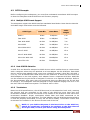
The configuration utility main menu options are:
Menu Option
Description
Quick Setup
Quickly create a single Array and Volume
RAID Management
Create single or multiple Arrays and Volumes with
custom parameters.
SCSI Configuration
Set SCSI parameters such as SCSI ID, speed and
Tag Queue.
System Management
Set System parameters such as Ethernet, Time,
password, Upgrade Firmware and Event Logs
Disk Management
Set disk utility such as view disk status and set
faulty.
User Manual
45
SCSI to SATA II RAID Subsystem
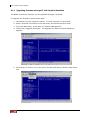
5.1.1 Upgrading Firmware through VT-100 Terminal Emulation
The RAID controller’s firmware can be upgraded through a terminal.
To upgrade the firmware, follow these steps:
1. Shut down the host computer system, if a host computer is connected.
2. Start a terminal connection to the disk array and access the Menu area.
3. From the Main Menu, scroll down to “System Management”
4. Choose the “Upgrade Firmware”. The Upgrade the Raid Firmware dialog box
appears.
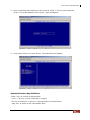
5. Press Enter to confirm. Go to the menu tool bar and select Transfer. Open Send
File.
46
User Manual
SCSI to SATA II RAID Subsystem
6. Click Browse. Locate where the Firmware file has been saved, select the file and
click Open.
7. Select “Ymodem” under Protocol. YMODEM is the file transfer protocol used by the
terminal emulation software.
8. Click “Send” to send the Firmware file to the RAID controller.
9. When Firmware download is completed, the subsystem will restart. Need to login
again to terminal after restart.
User Manual
47
SCSI to SATA II RAID Subsystem
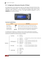
5.2 Configuring the Subsystem Using the LCD Panel
All configurations can be performed through the LCD Display front panel function keys,
except for the “Firmware update”. The LCD provides a system of screens with areas for
information, status indication, or menus. The LCD screen displays menu items or other
information up to two lines at a time. The RAID subsystem password is set to
00000000 by manufacture default.
Function Key Definitions
Parts
Function
Exit button
Press this button to return to the previous menu.
Select button
This is used to enter the option you have selected.
Up and Down
arrow buttons
Use the Up or Down arrow keys to move between
each menu when you configure the subsystem.
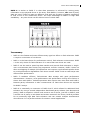
The following tree diagram is a summary of the various configurations and setting
functions that can be accessed through the LCD panel menus. Press the Select button
and enter the password to access the menu functions.
48
User Manual
SCSI to SATA II RAID Subsystem
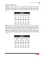
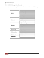
To view system information, hardware monitor information, array information, and other
related information, press the Down Arrow button.
Model-Name
RAID READY
IOP-80331 FW1.30
RAM:256MB HD#8
Temperature
System:40 C
S 1:34C S 2:31C
S 3:33C S 4:32C
S 5:34C S 6:29C
S 7:29C S 8:31C
MF/PSU-A: 3214rpm
MF/PSU-B: 3213rpm
Array1
IN USE ARRAY >
A: 899G Fr:399G
Level: RAID 5
Stripe Size:128K
Block Size:512 byte
Member disks:
1234
Disk Info
Disks: 8
Vol1
Size: 499.9 GB
>
(shows hard disk info, such as model, capacity)
User Manual
49
SCSI to SATA II RAID Subsystem
5.3 Configuration using the proRAID Manager GUI
The RAID subsystem can be managed through the controller’s Ethernet connection.
Any PC on the network to which the RAID subsystem is connected can manage the
subsystem using proRAID Manager. proRAID Manager is web browser-based
Graphical User Interface (GUI) that is supported on many OS platforms.
This chapter describes the steps that you need to start up ProRAID Manager and
how to use it on your system.
NOTE: Flash Player 10 or later version must be installed in the PC
which will be used to manage the RAID subsystem.
5.3.1 Login to proRAID Manager
Open a web browser and enter http://xxx.xxx.xxx.xxx, where xxx.xxx.xxx.xxx is the IP
address of the RAID subsystem. The Login screen will be displayed.
Enter the subsystem name (you can use any name to identify the subsystem you are
going to manage) and the password.
NOTE: The default IP address of the RAID system is 172.16.0.1.
The IP address can be verified from LCD panel; select System
Config and then Ethernet Config. The default subsystem password
is 00000000.
NOTE: The session timeout limit is 10 minutes. When the GUI is
not used within 10 minutes, user will be logged out automatically.
50
User Manual
SCSI to SATA II RAID Subsystem
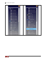
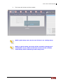
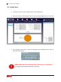
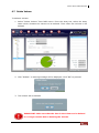
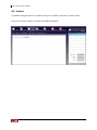
5.3.2 The ProRAID Manager Main Menu
After login, the Main Screen will be displayed. There are several menu items shown on
the upper part of the screen. The menu items are grouped according to their
functionality.
Each menu item can have several sub-menu items. Click the icon of the menu item and
the sub-menu will be displayed.
The right pane shows the list of subsystems that you have logged in to. You can login to
several subsystems at a time using a single proRAID Manager GUI.
to show or hide the proRAID Manager
On the left side of the screen is an icon
Menu Tree. The menu tree is a list form of the menu options available on the upper part
of the screen. It provides a quicker way to access the submenu items.
User Manual
51
SCSI to SATA II RAID Subsystem
52
User Manual
SCSI to SATA II RAID Subsystem
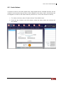
Mount or Detach RAID Subsystem
To login to another RAID Subsystem, click the Mount button and enter the Subsystem
Name (you can use any name to identify the subsystem you are going to manage), the
IP Address, and the subsystem Password. The subsystem name will appear in the list
of subsystem on the right screen.
To logout from a subsystem, select the subsystem name and click Detach. In the
confirmation screen, select OK to proceed with logout.
User Manual
53
SCSI to SATA II RAID Subsystem
5.3.3 ProRAID Manager Menu Hierarchy
Below is the summary of the menu and functions available in proRAID Manager
GUI.
Quick Setup
Create Array
Modify Array
RAID
Delete Array
Create Volume
Modify Volume
Delete Volume
Network Setting
SNMP Setting
Network
SMTP Setting
NTP Setting
Sync RTC
System Setting
Channel Manager
System
Modify Password
Upgrade Firmware
Restart
Event Log
Event Log
Export Log
Disk Info
Information
RAID
System Info
Hardware Monitor
Raid Task
S.M.A.R.T
54
User Manual
Raid Status
Disk Health
Diagnosis Disk
SCSI to SATA II RAID Subsystem
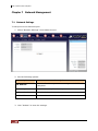
Chapter 6 RAID Management
This chapter describes the available RAID Management tasks; these tasks may be
selected using the RAID menu icon in the upper part of the screen or in the left side
menu of the ProRAID Manager screen. There are seven functions: Quick Setup, Create
Array, Modify Array, Delete Array, Create Volume, Modify Volume, and Delete Volume.
NOTE: Any FREE or un-used hard disk will automatically become
Global Hot Spare disk, which means it can replace any failed disk
in any Array, as long as the capacity is the same or greater than
the capacity of the smallest disk size in the Array.
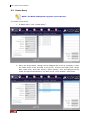
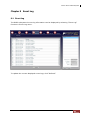
6.1 Quick Setup
The Quick Setup function provides an easy way for users to quickly configure a single
Array and Volume.
Here are the steps:
1.
In Raid menu, click “Quick Setup”.
User Manual
55
SCSI to SATA II RAID Subsystem
2.
Enter Array Name, Volume Name, select the disk drives to be included in
the Array, and select RAID Level, Stripe Size, and Block Size. Click
“Submit” when done.
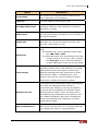
Option
Description
Array Name
The name of the array you want to assign to the
Array. It should not exceed 20 characters.
Volume Name
The name of the volume you wan to assign to the
Volume. After mapping the Volume as LUN, it will
appear as a disk device to the host.
RAID Level
Select the RAID Level you want the Array to use.
The RAID level option will depend on the number of
disk drives selected.
Stripe Size
This parameter sets the size of the stripe written to
each disk. You can set the stripe size to 8k, 16k,
32k, 64k, 128k, 256k or 512k.
Use this option to enable creating Volume over
2TB.
Block Size
56
User Manual
For Windows OS, such as Windows 2000, 2003:
Use 1KB, 2KB or 4KB.
For 64bit LBA mode, such as Windows 2003+SP1
or later versions, Linux 2.6 or later versions:
Use 512 bytes. Due to LSI chip limitation,
16 Byte CDB option must run at U320 mode.
SCSI to SATA II RAID Subsystem
3.
The Array and Volume will be created.
NOTE: Quick Setup can only be used if there’s no existing Array.
NOTE: In Quick Setup, the Array will be created in background
initialization mode, which means the Volume will be available
immediately while initializing in the background.
User Manual
57
SCSI to SATA II RAID Subsystem
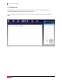
6.2 Create Array
NOTE: The RAID subsystem supports up to 8 Arrays.
To create a new Array:
1. In RAID menu, click “Create Array”.
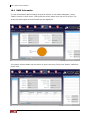
2. Enter the Array Name, change the Re-Mapped BS count as necessary, select
the disks drives to be included in the Array, and set the RAID Level, Stripe
Size, Block Size, and Task Priority. Other options, such as Background Init
mode and Ignore Bad Sectors, can also be set. Click “Submit” when done.
58
User Manual
SCSI to SATA II RAID Subsystem
Option
Description
Array Name
The name of the array you want to assign to the
Array. Maximum is 20 characters.
Capacity
The total capacity of the Array in GB.
Re-Mapped BS count
Set the maximum number of bad sector count to be
remapped. Default is 1000. Maximum number of
bad sector is 10,000.
RAID Level
Select the RAID Level you want the Array to use.
The RAID level option will depend on the number of
disk drives selected.
Stripe Size
This parameter sets the size of the stripe written to
each disk. You can set the stripe size to 8k, 16k,
32k, 64k, 128k, 256k or 512k.
Use this option to enable creating Volume over
2TB.
Block Size
For Windows OS, such as Windows 2000, 2003:
Use 1KB, 2KB or 4KB.
For 64bit LBA mode, such as Windows 2003+SP1
or later versions, Linux 2.6 or later versions:
Use 512 bytes. Due to LSI chip limitation,
16 Byte CDB option must run at U320 mode.
Task Priority
The priority for background tasks, such as
rebuilding. Options are: LOW, MEDIUM, and HIGH.
LOW priority means less system resources are
allotted to background task, and access to Array
and Volume is faster. In HIGH priority, more
system resources are used for background task,
and access to Array and Volume is slower.
Background Init
The default Array Initialization mode is Foreground
Init mode (the Background Init option is
unchecked) and Volume(s) can only be added to
the Array after initialization is completed. When
Background Init mode is used, the Array will be
accessible during initialization and Volume(s) can
be created immediately. Note that accessing the
Array during background initialization can have
performance impact.
Ignore Bad Sectors
Use this option to Ignore Bad Sectors. This option is
used when rescuing Array. It is recommended that
you disable this option in normal situation.
User Manual
59
SCSI to SATA II RAID Subsystem
3. The Array will be initialized.
4. The next step is to create a Volume. When Array has completed its
initialization in Foreground mode, or still initializing in Background mode, a
Volume can created.
NOTE: Any FREE or un-used hard disk will automatically become
Global Hot Spare disk, which means it can replace any failed disk
in any Array, as long as the capacity is the same or greater than
the capacity of the smallest disk size in the Array.
60
User Manual
SCSI to SATA II RAID Subsystem
6.3 Modify Array
Use this function to modify settings of an existing Array
To modify Array:
i.
In RAID menu, click “Modify Array”. Change the settings of the Array as
necessary.
NOTE: Some settings are read-only and cannot be modified.
ii.
Click “Submit” when done. The modified Array will be saved.
User Manual
61
SCSI to SATA II RAID Subsystem
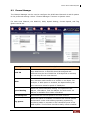
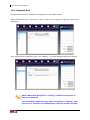
6.4 Delete Array
1. To delete an Array, select “Delete Array” from RAID menu.
2. Select the Array to be deleted from the list of Arrays displayed on the left side.
3. Click “Submit” when done. A warning message will be displayed. Click “OK” to
proceed with deletion.
IMPORTANT: Make sure that the data in the Array to be deleted is
no longer needed before deleting an Array.
62
User Manual
SCSI to SATA II RAID Subsystem
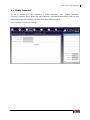
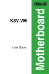
6.5 Create Volume
A Volume is seen by the host system as a single logical device. Multiple Volumes can be
created in an Array as long as there is free capacity in the Array. Up to 32 Volumes can
be mapped to a LUN in each Host Channel (LUN ID 0 to 31 for Host A and for Host B).
1. To create a Volume, select “Create Volume” from RAID menu.
2. From the list of Array in the left column, select the Array where the Volume will
be created.
User Manual
63
SCSI to SATA II RAID Subsystem
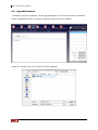
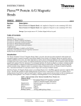
3. Enter the Volume Name, the Volume Size, and change the Read Ahead option if
necessary. Map the Volume to a LUN by enabling the Activate option and
selecting the LUN ID in the Host Channel.
Option
Description
Volume Name
The name you want to assign to the Volume.
Maximum is 20 characters.
Volume Size
The capacity you want to give to the Volume; value
is in GB. Note that the available capacity that can be
used in displayed in Maximum Capacity field.
Read Ahead
The Maximum number of Read Ahead is 99. The
controller will read ahead to optimize performance
on sequential reads.
Activate
Enable this option to activate the Volume in the
selected Host Channel (A and/or B).
Host A, Host B - LUN #
The LUN ID in the Host Channel assigned to the
Volume. Each Host Channel has 32 LUN IDs.
64
User Manual
SCSI to SATA II RAID Subsystem
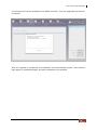
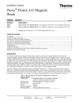
4. Click “Submit” when done. The Volume will be created.
IMPORTANT: Once a LUN number is already assigned to a Volume,
it cannot be used again.
User Manual
65
SCSI to SATA II RAID Subsystem
6.6 Modify Volume
The Volume attributes can be modified using the “Modify Volume” function in RAID menu.
To modify a Volume:
1. Select “Modify Volume” from RAID menu. Select the Array name from the Array
List, and then select the Volume to be modified.
2. Change the settings as necessary. Note that some settings cannot be modified.
3. Click “Submit” when done. The modified Volume settings is saved.
66
User Manual
SCSI to SATA II RAID Subsystem
6.7 Delete Volume
To delete a Volume:
1. Select “Delete Volume” from RAID menu. From the Array List, select the Array
name which contains the Volume to be deleted. Then select the Volume to be
deleted.
2. Click “Submit”. A warning message will be displayed. Click “OK” to proceed.
3. The Volume will be deleted.
IMPORTANT: Make sure that the data in the Volume to be deleted
is no longer needed before deleting the Volume.
User Manual
67
SCSI to SATA II RAID Subsystem
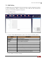
Chapter 7 Network Management
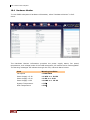
7.1 Network Settings
To setup the R-Link Ethernet port:
1. Select “Network Settings” from Network menu.
2. Set the following options:
Option
Description
IP Address
Enter the IP address you want to assign to the RAID
subsystem.
Gateway
Enter the Gateway IP Address you want to use.
Subnet Mask
Enter the Subnet Mask value.
MAC Address
This shows the MAC Address of the network interface.
3. Click “Submit” to save the settings.
68
User Manual
SCSI to SATA II RAID Subsystem
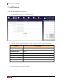
7.2 SNMP Setting
The SNMP gives users independence from the proprietary network management schemes
of some manufacturers. SNMP is supported by many WAN and LAN manufacturers
enabling true LAN/ WAN management integration.
To set the SNMP function:
1. Select “SNMP Setting” from Network menu.
2. Tick the “Enable SNMP Notification” option. Then setup the necessary options.
Option
Description
Description
Enter a description.
Contact
Enter the Contact information.
Name
Enter the Name information.
Location
Enter the Location information.
GetCommunity
Enter or change the GetCommunity value if needed.
SetCommunity
Enter of change the SetCommunity value if needed.
Trap ID 1
Enter the first Trap receiver IP address.
Trap ID 2
Enter the second Trap receiver IP address.
Trap ID 3
Enter the third Trap receiver IP address.
3. Click “Submit” to save the settings.
User Manual
69
SCSI to SATA II RAID Subsystem
7.3 SMTP Setting
To set the Mail Notification function:
1. Select “SMTP Setting” from Network menu.
2. Tick the “Enable Mail Notification” option. Then setup the necessary options.
Option
Description
SMTP Server
Enter the SMTP Server IP address.
Use Secure
Authentication
To use secure authentication in SMTP server, enable this
option.
Account
Enter the account information.
Password
Enter the password for the account.
Sender
Enter the sender’s email address.
Receiver
Enter the receiver’s email address.
3. Click “Submit” to save the settings.
70
User Manual
SCSI to SATA II RAID Subsystem
7.4 NTP Setting
NTP (Network Time Protocol) is an Internet standard protocol used to synchronize the
clocks of computers to some time reference.
By default, “Use Local Time Setting” is selected. This means the RAID subsystem will get
time information from local computer. Whenever the RAID subsystem is started or
restarted, you need to use “Sync RTC”. RTC Stands for Real Time Clock and is used to
set the time on the RAID controller. Setting the correct time plays an important role in
the system administration which helps administrators keep accurate record of when the
events actually occur.
To set the NTP function:
1. Select “NTP Setting” from Network menu.
2. Select the “Sync with a NTP Server” option. Then setup the necessary options.
Option
Description
Time Zone
Select the local time zone.
NTP Server
Enter the NTP Server IP Address.
3. Click “Submit” to save the settings.
User Manual
71
SCSI to SATA II RAID Subsystem
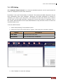
7.5 Sync RTC
When time setting is not configured to get time from an NTP server (“Use Local Time
Setting” option is selected in NTP Setting), the “Sync RTC” function must be used
whenever the RAID subsystem is started or restarted.
RTC Stands for Real Time Clock and is used to set the time on the RAID controller.
Setting the correct time plays an important role in the system administration which helps
administrators keep accurate record of when the event actually occurs.
To Sync RTC, select “Sync RTC” from Network menu and click “Submit".
72
User Manual
SCSI to SATA II RAID Subsystem
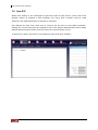
Chapter 8 System Management
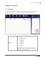
8.1 System Setting
Some RAID subsystem System settings can be configured to the user’s preference to
match certain application.
The following can be set using “System Setting” function in System menu:
Alarm Beeper:
The Alarm Beeper function item is used to Disable or Enable the RAID subsystem
alarm tone generator. When Alarm Beeper option is checked, the alarm beeper is
enabled.
Cache Type:
The RAID subsystem supports Write Through and Write Back cache type. Write
Back allows temporary saving of data in the volatile cache memory and data are
acknowledged to have been received once it reaches the cache memory. Write
Through allows saving the data in the disk drives and data confirmation is
acknowledged once the data are written to the disk drives.
Cache Ratio:
Select 10% to 90% or adaptive.
User Manual
73
SCSI to SATA II RAID Subsystem
Notification Level:
Events are classified to 5 levels (Critical, Error, Warning, Notice, Info).
Event
Log Level
Slot inserted
Notice
Slot removed
Notice
Temperature back to normal
Notice
Voltage back to normal
Notice
PSU back to normal
Notice
Fan back to normal
Notice
UPS not present
Notice
UPS standby
Notice
Array deleted
Notice
Array created
Notice
Array modified
Notice
Array initialization completed
Notice
Array rebuild completed
Notice
Array expansion completed
Notice
Array parity checking completed
Notice
Disk clone succeeded
Notice
Volume created
Notice
Volume deleted
Notice
Volume modified
Notice
Over temperature
Warning
Over voltage
Warning
Low voltage
Warning
PSU not present
Warning
Fan not present
Warning
Fail to setup network configuration
Warning
Array initialization failed
Warning
Array rebuild failed
Warning
Array expansion failed
Warning
Array parity checking failed
Warning
Disk clone failed
Warning
Mirror disk clone failed
Warning
System restart
Warning
Parity error detected
Warning
Power Supply Unit(PSU) Fail
Error
Fan fail
Error
UPS on battery
Error
Bad sector reallocation
Info
Baud Rate:
Set the baud rate: 19200, 38400, 57600 or 115200 (Default: 115200)
To save the change in each setting, click the “Submit" button.
74
User Manual
SCSI to SATA II RAID Subsystem
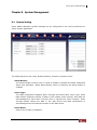
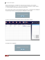
8.2 Channel Manager
The Channel Manager can be used to configure the SCSI Host Channels A and B options
to the preferred settings. Select “Channel Manager” function in System menu.
For each Host Channel, the SCSI ID, Wide, Speed Setting, Current Speed, and Tag
Queue can be set.
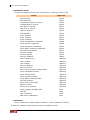
Option
Description
SCSI ID
Select 0 to 15 or Multiple ID. The RAID subsystem is like a
large SCSI device. A SCSI ID should be assigned and
selected from the list of SCSI IDs. If Multiple ID is selected,
you can map ID to a host channel.
Wide
If enabled for a wide bus, the throughput is double transfer
rate, because each transfer is of 16 bits or two bytes. For
example, if Wide option is enabled, the Speed Setting can
have maximum transfer speed of 320MB/sec.
Speed Setting
Select the preferred Speed setting. The options are 80
MB/sec, 160 MB/sec, and 320 MB/sec for Wide mode. 40
MB/sec is available when Wide is disabled.
Current Speed
This shows the current speed for the host channel.
Tag Queue
When this option is enabled, it enhances the overall system
performance under multi-tasking operating systems by
reordering tasks or requests in the command queue of the
RAID system. This function should normally remain enabled.
User Manual
75
SCSI to SATA II RAID Subsystem
After setting the preferred option, click “Update” to save the changes.
To see the current settings, click “Refresh”.
76
User Manual
SCSI to SATA II RAID Subsystem
8.3 Modify Password
To set or change the login password of RAID subsystem, click “Modify Password”
function in System menu. Enter the old password in the Old Password field, and the new
password in the New Password and Confirm New Password fields.
Click “Submit” to save the change.
User Manual
77
SCSI to SATA II RAID Subsystem
8.4 Upgrade Firmware
The RAID controller’s firmware can be upgraded when new firmware version is available.
Select “Upgrade Firmware” function in System menu then click “Upload”.
Select the firmware file. Click “Open” to start updating.
78
User Manual
SCSI to SATA II RAID Subsystem
The firmware file will be uploaded to the RAID controller. Then the upgraded process will
be started.
After the upgrade is completed, the subsystem will automatically restart. User needs to
login again to proRAID Manager GUI after subsystem has restarted.
User Manual
79
SCSI to SATA II RAID Subsystem
8.5 Restart
The RAID subsystem can be restarted using the “Restart” function in System menu.
Click the “Submit” button to restart the RAID subsystem.
80
User Manual
SCSI to SATA II RAID Subsystem
Chapter 9 Event Log
9.1 Event Log
The RAID subsystem’s event log information can be displayed by selecting “Event Log”
function in Event Log menu.
To update the current displayed event logs, click “Refresh”.
User Manual
81
SCSI to SATA II RAID Subsystem
9.2 Export Log
The RAID subsystem’s event log information can be saved to local destination by
selecting “Export Log” function in Event Log menu.
Click “Submit” to save the event log. The file type of the exported event log will be in
XML.
82
User Manual
SCSI to SATA II RAID Subsystem
Chapter 10 Information
10.1 Disk Information
To view detailed information about the disk drives in the RAID subsystem, select “Disk
Info” function in Info menu. The Slot ID (Disk#), the disk vendor, model, capacity,
number of remapped bad sectors, firmware version, and state are shown.
When disks are already member of an Array, the State will show USED. It will show FREE
when not yet used.
Each member disk drive can be mark as faulty. Click the “Mark Faulty” button for the
disk drive.
NOTE: Setting disk as faulty can cause unrecoverable data damage
for some RAID levels. Use this function with caution.
User Manual
83
SCSI to SATA II RAID Subsystem
10.2 RAID Information
To view information about existing Array and Volume in the RAID subsystem, select
“RAID” function in Info menu. Then select the Array name from the list of Arrays. The
Array Info and Logical Volume Details will be displayed.
The logical volume details can be shown in grid view using “Grid View” button. Default is
Chart View.
84
User Manual
SCSI to SATA II RAID Subsystem
10.3 System Information
Use the “System Info” function in Info menu to view the RAID subsystem information.
The Vendor Name, Serial No., Product ID, CPU Name, CPU Speed, Memory Size, Memory
Speed, BBM Module installed or not, ECC DRAM support, Subsystem Model, Controller
Model, Firmware Version, Disk Channel Type, Number of Host Channels, Host Channel
Type, Host Channel Sync Speed, Number of Slots, Number of Backplane Slots, Baud
Rate, Cache Type, Cache Ratio, Beeper enabled or not, Log Level, proSES enabled or not,
and JBOD Model appear in this screen.
User Manual
85
SCSI to SATA II RAID Subsystem
10.4 Hardware Monitor
To view RAID subsystem’s hardware information, select “Hardware Monitor” in Info
menu.
The Hardware Monitor information provides the power supply status, fan speed,
temperature, and voltage levels of the RAID subsystem. All items are also unchangeable.
The warning messages will indicate through the LCD, LED and alarm buzzer.
86
Item
Warning Condition
Fan Speed
< 2000 RPM
Power Supply +3.3V
< 2.97V or > 3.63V
Power Supply +5.0V
< 4.5V or > 5.5V
Power Supply +12V
< 10.8V or > 13.2V
System Temperature
> 70℃
HDD Temperature
> 55℃
User Manual
SCSI to SATA II RAID Subsystem
Chapter 11 Raid Task
11.1 Raid Status
To view the RAID status of an Array, select “Raid Status” in Raid Task menu. The List of
Arrays, and the RAID Level, Capacity, Member Disks and Status are displayed.
The states available are:
Status
Ready
Need to Rebuild
Initializing
Rebuilding
Expanding
Verifying
Cloning
Fail
If the RAID is rebuilding, initializing, expanding,
checking or cloning, the progress of the task will be
displayed, e.g. ‘Initializing 75%’.
User Manual
87
SCSI to SATA II RAID Subsystem
A Parity Check function is available for existing Arrays with parity, such as those
configured with RAID level 3, 5, 6, 30, or 50, to check the consistency of parity blocks,
i.e. verify that parity information matches the stored data.
Click “Check Parity” button to start performing parity check. A message will be displayed.
The percentage of parity checking progress is displayed in Status field.
To cancel current Parity Check process, click the “Cancel Parity” button.
A message will be displayed.
88
User Manual
SCSI to SATA II RAID Subsystem
Chapter 12 S.M.A.R.T.
12.1 Disk Health
The RAID subsystem uses the SMART (Self-Monitoring, Analysis and Reporting
Technology) information available in the disk drive to monitor the disk health.
To view SMART information of a disk drive, select “Disk Health” in S.M.A.R.T. menu.
Then click the disk drive. The Disk ID and Disk Status of the selected disk are displayed.
The SMART attributes and its values and threshold values are also shown.
The Threshold Value is the boundary for the attribute Value before the disk
becomes unstable. The higher the attribute Value compared to the Threshold Value,
the better. If the attribute Value becomes smaller than the Threshold Value, the disk
is not in good state.
User Manual
89
SCSI to SATA II RAID Subsystem
12.2 Diagnosis Disk
A diagnostic function is available to diagnose the disk health status.
Select “Diagnosis Disk” in S.M.A.R.T. menu. There are two types of diagnosis: Quick and
Extended.
After selecting the Diagnosis Type, click “Submit”. The disk diagnosis process will start.
NOTE: When Disk Diagnosis is running, it cannot be stopped. It
must be completed.
The “Extended” Diagnosis Type takes long time to complete, from
few hours to several hours depending on the size of the hard disk.
90
User Manual