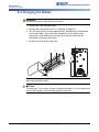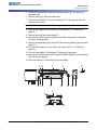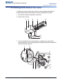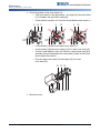
1
BP-PR PLUS & BBP72 Series
Perforation Cutter
Operator’s Manual
Edition 04/10
Configuration
Instructions
Y1147484
Edition 12/09
Information on the scope of delivery, appearance, performance, dimensions and
weight reflect our knowledge at the time of printing. We reserve the right to make
modifications.
All rights, including those regarding the translation, are reserved. The replication,
conversion, duplication or divulgement of the whole manual or parts of it for other
intentions than its original intended purpose demand the previous written
authorization by Brady Corporation.
Edition 04/10
Brady Worldwide
6555 W. Good Hope Road
PO Box 2131
Milwaukee, WI 53201 U.S.A.
Phone: 1-800-537-8791 Fax: 1-800-292-2289
ii Edition 04/10
W.H. Brady
Lindestraat 21
Industriepark C3
9240 Zele Belgium
Tel.: +32 52 457 811
e-mail: [email protected]
PERFORATION CUTTER OPERATOR ’S MANUAL
Approval
The transfer printers comply with the following safety guidelines:
CE
EC Low-Voltage Directive (73/23/EEC) EC Machine Directive (98/37/EC) EC
Electromagnetic Compatibility Directive (89/336/EEC)
FCC
Conditions from Part 15 of the FCC Regulations for Class A computing devices.
Operation of these devices may cause radio or television interference under
unfavorable conditions, which would need to be remedied by the operator using
countermeasures.
Batteries Directive 2006/66/EC
This product contains a lithium battery. The crossed-out wheeled bin is
used to indicate ‘separate collection’ for all batteries and accumulators
in accordance with European Directive 2006/66/EC. Users of batteries
must not dispose of batteries as unsorted municipal waste. This
Directive determines the framework for the return and recycling of used
batteries and accumulators that are to be collected separately and
recycled at end of life. Please dispose of the battery according to your
local regulations.
Notice to Recyclers
To remove the lithium battery:
1. Disassemble printer and locate the lithium cell battery located on the main
circuit board.
2. To remove, slide the battery from the coin cell retainer, remove the battery
from the board, and dispose of properly.
PERFORATION CUTTER OPERATOR ’S MANUAL
iii Edition 04/10
Contents
1 Introduction ......................................................................... 1
1-1
1-2
1-3
1-4
2
3
4
5
6
Intended Use ..................................................................................... 1
Safety Instructions ............................................................................. 2
Environment ..................................................................................... 3
Technical Data ................................................................................. 3
Mounting ............................................................................. 4
Printer Configuration .......................................................... 5
Loading Material .................................................................. 8
Operation ............................................................................. 8
Maintenance .......................................................................10
6-1 Cleaning .......................................................................................... 10
6-2 Changing the Blades ....................................................................... 12
6-3 Setting Initial State of the Cutter ...................................................... 15
7 Compliance ........................................................................17
7-1 UNITED STATES & CANADA ....................................................... 17
7-2 EU Conformity Declaration .............................................................. 18
iv Edition 04/10
PERFORATION CUTTER OPERATOR ’S MANUAL
1 Introduction
1-1 Intended Use
The device is intended exclusively as an option for the printers of the PR PLUS
printer series (serial number 83761+) and BBP72 printer for cutting suitable
materials that have been approved by the manufacturer. Any other use or use
going beyond this shall be regarded as improper use. The manufacturer/supplier
shall not be liable for damage resulting from unauthorized use; the user shall bear
the risk alone.
Usage for the intended purpose also includes complying with the operating
manual, including the manufacturer‘s maintenance recommendations and
specifications.
The device is manufactured in accordance with the current technological status
and the recognized safety rules. However, danger to the life and limb of the user
or third parties and/or damage to the device and other tangible assets can arise
during use.
The device may only be used for its intended purpose and if it is in perfect working
order, and it must be used with regard to safety and dangers as stated in the
operating manual.
PERFORATION CUTTER OPERATOR ’S MANUAL
1 Edition 04/10
Introduction
Safety Instructions
1-2 Safety Instructions
•
Disconnect the printer from the electrical outlet before mounting or removing
the cutter.
•
The cutter may only be operated when it is mounted on the printer.
•
Risk of injury, particularly during maintenance, the cutter blades are sharp.
CAUTION!
Rotating knife. Do not touch or put fingers near knife.
2 Edition 0410
•
Work going beyond this may only be performed by trained personnel or service
technicians.
•
Unauthorized interference with electronic modules or their software can cause
malfunctions. Other unauthorized work or modifications to the device can also
endanger operational safety.
•
Always have service work done in a qualified workshop, where the personnel
have the technical knowledge and tools required to do the necessary work.
•
Do not remove warning stickers, as then you and other people cannot be aware
of dangers and may be injured.
PERFORATION CUTTER OPERATOR ’S MANUAL
Introduction
Technical Data
1-3 Environment
Obsolete devices contain valuable recyclable materials that should be sent for
recycling.
• Send to suitable collection points, separately from residual waste.
The modular construction of the printer enables it to be easily disassembled into
its component parts.
• Send the parts for recycling.
• Take the electronic circuit boards to public waste disposal centers or to the
distributor.
1-4 Technical Data
Description
For printer type:
Perforation Cutter
Catalog Number: PR+-PerfCutter-FI
PR-300 PLUS
PR-600 PLUS
Perforation distance
2.5 mm
Off-cut width
0.5 mm
Perforation length min.
2 mm
Cut length min.
12 mm
Material width
Passage height
Power supply
up to 120 mm
4.5 mm
peripheral connector of the printer
Note: To operate the Perforation Cutter, printer firmware version 3.13 or higher
must be installed. See "3: Printer Configuration" on page 5 for setup details.
Note: For very thin, very hard or very flexible materials preliminary tests are
recommended.
The cutters have a durability of more than 500,000 cuts. Depending on the type of
the cut material the blades could wear earlier and have to be replaced. Used
blades are not designed to be grinded again.
PERFORATION CUTTER OPERATOR ’S MANUAL
3 Edition 04/10
Mounting
Technical Data
2 Mounting
Note: Disconnect the printer from the electrical outlet before mounting or removing
the cutter.
1. Loosen the screws [2].
2. Remove the front cover [1].
1
2
Note: For cutter operation with PR PLUS printer series and BBP72 printer there
has to be mounted a tear-off plate or a dispense plate on the printer, to lead the
material through the blades of the cutter.
3. Insert the pins [3] of the cutter [7] into the holes [4] of the printer.
4. Press the cutter against the printer. That way the plug of the cutter will be
connected to the peripheral port [5] of the printer.
5. Secure the cutter [7] with the screw [6].
3
6
4 Edition 0410
4
5
4
7
PERFORATION CUTTER OPERATOR ’S MANUAL
Printer Configuration
Technical Data
3 Printer Configuration
Once the cutter is connected to the printer, the printer will automatically recognize
it once the printer is turned on.
The printer can be configured to suit the individual requirements of cut mode in
the Setup menu. When the cutter is installed, the Cutter menu will appear.
Note: For detailed instructions for configuration see the printer User Manual.
Note: The print driver version must be v4.6.21 or higher.
The cutter requires additional setup in the driver. Setup is done on the Advanced
Setup tab as shown in the graphic. Sensor type selection is based on the material
used.
PERFORATION CUTTER OPERATOR ’S MANUAL
5 Edition 04/10
Printer Configuration
Technical Data
1. For setting the cutter parameters select:
Setup
> Machine param.
Parameter
> Cutter
.
Meaning
Default
Cutter
Configuration of the perforation cutter
> Cut position
Offset of the cut position relative to the printed 0
image.
> Cutting Depth
Setting of the perforation depth.
0
Notes:
• Cutting depth can be set from -20 to 20. Adjust to determine optimal depth for
the material.
• The values of the setup are basic settings for the actual combination printer/
cutter. After changing the cutter or printer, a re-adjustment may be necessary.
• Changes required for processing different print jobs should be implemented in
additional offsets available in the software.
• The offset values from setup and software are added together for execution.
6 Edition 0410
PERFORATION CUTTER OPERATOR ’S MANUAL
Printer Configuration
Technical Data
2. Select the method for recognizing the material and the method of backfeed
when using cut mode under Setup
Parameter
Label
sensor
-> Print parameters
Meaning
.
Default
Gap
Method for detecting the starting end of the label.
To operate the perforation cutter, typically choose the sensor
setting Continuous media.
Gap Sensor: Detection using changes in the
transparency between the label and label gap.
Bottom-Reflect: Detection using reflex marks on the
bottom of the medium.
Continuos media: Synchronization of the paper
feed when using endless media in cutting mode.
X After loading media, press the feed key to
recognize a short feed and synchronization cut.
smart
Backfeed Method for backfeeding the material.
Backfeeding is necessary in the cutting mode since
the front edge of a second section already passes the
print line when the first label is moved to the cut
position.
always: Backfeeding occurs independently of print
contents.
smart: Backfeeding only occurs when the print
contents of the next section is not yet fully prepared
when cutting the current section. Otherwise, the
second section is pushed on and completed after
removal of the first section without backfeeding.
PERFORATION CUTTER OPERATOR ’S MANUAL
7 Edition 04/10
Loading Material
Technical Data
4 Loading Material
•
Load transfer ribbon and endless material as described in the Operator’s
Manual of the printer.
Use the tear-off mode information for loading endless material for cut mode.
•
Place the media strip between the printhead and the drive roller, so that the
front edge of the strip reaches through the cutter.
Note: To prevent jamming, we recommend that material be loaded so that it exits
from the top of the roll.
5 Operation
The printer is ready for operation when all connections have been made and all
materials are loaded correctly.
Note: To operate the cutter with continuous material, in the printer menu select
Setup > Print parameters>Label sensor the setting Endless media. Otherwise
no synchronization cut is carried out.
1. Switch on the printer.
The cutter performs a complete cut-off.
2. Press the feed key. For synchronization the media will be moved forward and
cut off.
Synchronization is not necessary when the printhead was not opened
between print jobs, even if the printer was powered off between print jobs.
3. Activate the commands for perforation or cut-off in the software.
For direct programming use the following commands:
Cp
Perforation command
C
Cut-off command
(see the Programming Manual)
Both commands may be combined, but C p has a lower priority.
Using the sequence :
C3
Cp
the material will be perforated two times and afterwards cut off.
Note: In several label software solutions, the perforation command C p is not
implemented. Perforating material via such a software is not possible.
8 Edition 0410
PERFORATION CUTTER OPERATOR ’S MANUAL
Operation
Technical Data
4. For direct programming use the following command :
O Cn
n...Value between 0.0 and 10.0
Note: If label software has no setting for cutting depth (i.e., O Cn is not
implemented), adjustment also may be done using printer setup (see "3: Printer
Configuration" on page 5).
All labels in a print job will be printed without stopping and be perforated or cut
as chosen in the software: after each label, after a specific quantity of labels,
or at the end of a print job.
PERFORATION CUTTER OPERATOR ’S MANUAL
9 Edition 04/10
Maintenance
Cleaning
6 Maintenance
6-1 Cleaning
WARNING
Disconnect the printer from the electrical outlet.
DANGER!
Risk of injury. The cutter blades are sharp.
1. Remove the cutter from the printer.
2. Loosen the screws [2] and remove the upper cover sheet [1].
10 Edition 0410
PERFORATION CUTTER OPERATOR ’S MANUAL
Maintenance
Cleaning
3. Remove dust and paper particles with a soft brush or a vacuum.
4. For cleaning the circular blade it is possible to turn the axle [3] with a
screwdriver for slotted head screws (slot width 7 mm). The turn angle is
limited by the support [7].
If it is necessary to turn the circular blade further, loosen the screws [6] and
remove the support [7] incl the lower cover sheet [8]. Now the circular blade
can be turned completely.
5. Remove all deposits at the cutter blades with isopropyl alcohol and a soft
cloth.
6. Grease the cylindrical areas [4] at both ends of the circular blade [5] with an
All round-High quality Grease. For that hold a greased brush on the cylindrical
areas and turn the axle [3] with a screwdriver for slotted head screws (slot
width 7 mm).
During the turning, the areas are all-around greased.
7. If the support was removed during cleaning, adjust the initial state of the cutter
(see "6-3: Setting Initial State of the Cutter" on page 15) .
8. Mount the upper cover sheet [1] with the screws [2] and the support [7]
including the lower cover sheet [8] with the screws [6].
3
6 7
PERFORATION CUTTER OPERATOR ’S MANUAL
3
4
8
5
6
11 Edition 04/10
Maintenance
Changing the Blades
6-2 Changing the Blades
WARNING
Disconnect the printer from the electrical outlet.
1. Remove the cutter from the printer.
2. Remove the cover sheets (see "6-1: Cleaning" on page 10).
3. Turn the axle [3] of the circular blade [2] with a screwdriver for slotted head
screws (slot width 7 mm) so that the inscription [1] of the blade points
downward. In this position the set screw [4] on the gear wheel can be
achieved from the rear of the cutter.
4. Loosen the set screw [4] a few turns.
4
1
2
3
Note: Save the washers (A, B, C) for the circular blade [2] and the lineal blade [12]
when dismounting the cutter.
CAUTION!
The springs [6, 13] are tense. Always hold tight lineal blade [11] in its position and
push its axle slightly to the mounting plate [9] of the cutter.
12 Edition 0410
PERFORATION CUTTER OPERATOR ’S MANUAL
Maintenance
Changing the Blades
5. Loosen the screws [8] and remove the bearing plate [15]. The spring [13]
becomes slack.
6. Remove spring [13] from the lineal blade.
7. Pull the circular blade [2] out of the bearing [5]. The spring [6] at the lineal
blade becomes slack.
Note: If the lineal blade should not be changed, skip to step 13.
8. Remove the support incl. the lower cover sheet (see "6-1: Cleaning" on
page 10).
9. Remove spring [6] and lineal blade [11].
10. Insert the axle of the (new) lineal blade withe the washer (B) in the bearing
[10] of the mounting plate.
11. Hang in the slack spring [6] to the pins of the mounting plate [9] and the lineal
blade [11].
12. Re-mount the support incl. the lower cover sheet (see "6-1: Cleaning" on
page 10).
13. Turn the lineal blade [11] backwards. The spring [6] gets tense.
14. Insert the Axle of the (new) circular blade [2] with the washer (A) in the bearing
[5] of the mounting plate.
15. Place the washer (C) on the axle of the lineal blade.
5 6
7
9 10
11
A
B
PERFORATION CUTTER OPERATOR ’S MANUAL
2
8
12
13 14 15
2
11
C
13 Edition 04/10
Maintenance
Changing the Blades
16. Hang in the slack spring [13] to the pins [12,14] of the lineal blade and the
bearing plate.
17. Push the bearing plate [15] onto the blade axles [2, 11]. The spring [13] gets
tense.
18. Append the bearing plate [15] to the profile [7] using the screws [8].
19. Tighten the set screw [4] at the gear wheel.
20. Turn the circular blade [2] in such a position that the edges of the circular and
lineal blade touch each other.
21. Tighten the screws [8] and check that circular and lineal blade touch each
other. If necessary loosen and tighten the screws [8] again.
22. Lubricate the circular blade (see "6-1: Cleaning" on page 10) and adjust its
initial state (see "6-3: Setting Initial State of the Cutter" on page 15).
23. Re-mount the upper cover sheet (see "6-1: Cleaning" on page 10).
14 Edition 0410
PERFORATION CUTTER OPERATOR ’S MANUAL
Maintenance
Setting Initial State of the Cutter
6-3 Setting Initial State of the Cutter
To operate the cutter correctly after cleaning or after changing the blades the
circular blade [4] and the clock wheel [11] must be adjusted to each other.
1. Unscrew the screws [1], [3] and [6, at the rear].
2. Remove the cover [2].
1
2
3
4
5
6
6
3. Turn the axle [5] of the circular blade with a screwdriver for slotted head
screws (slot width 7 mm) so that the planar area [8] of the blade axle becomes
parallel to the base plate [7].
7
PERFORATION CUTTER OPERATOR ’S MANUAL
8
15 Edition 04/10
Maintenance
Setting Initial State of the Cutter
4. Check the position of the clock wheel [11].
• If the clock wheel is in the right position 1, the edge [10] of the clock wheel
[11] is located in the area of the marking [9].
• If clock wheel is in position 2 or 3 turn the circular blade to reach position 1:
9 10 11
•
•
•
•
9
10
9
10
Loosen screws [12] and remove upper cover sheet [13].
Loosen screws [14] and remove support [15] incl. lower cover sheet [16].
Turn the circular blade by one or two full turns, until the planar area [8] of
the blade axle becomes parallel to the base plate [7] again and the clock
wheel reaches the position 1.
Re-mount upper cover sheet [13] and support [15] incl. lower
cover sheet [16].
12 13 12
14 15 16 14
5. Mount the cover.
16 Edition 0410
PERFORATION CUTTER OPERATOR ’S MANUAL
Compliance
UNITED STATES & CANADA
7 Compliance
7‐1 UNITED STATES & CANADA
FCC Class A Notice (Printer with Optional Cutters, Type CU X, PCU X)
This device complies with Part 15 of the FCC Rules. Operation is subject to the following two
conditions:
1. This device may not cause harmful interference.
2. This device must accept any interference received, including interference that
may cause undesired operation.
Note: This equipment has been tested and found to comply with the limits for a Class A
digital device, pursuant to Part 15 of the FCC Rules. These limits are designed to provide
reasonable protection against harmful interference when the equipment is operated in a
commercial environment. This equipment generates, uses, and can radiate radio frequency
energy, and if it is not installed and used in accordance with the instruction manual, it may
cause harmful interference to radio communications. Operation of this equipment in a
residential area is likely to cause harmful interference, in which case the user will be required
to correct the interference at his/her own expense.
Modifications: Any modifications made to this device that are not approved by the Brady
Corporation may void the authority granted to the user by the FCC to operate this equipment.
ICES-003 Class A Notice, Classe A (Printer with Optional Cutters, Type CU X, PCU X)
This Class A digital apparatus meets all requirements of the Canadian Interference-Causing
Equipment Regulations.
Cet appareil numerique de la classe A respecte toutes les exigences du Reglement sur le
Materiel Brouilleur du Canada.
Safety Certification (Printer with Optional Cutters, Type CU X, PCU X)
This device complies with the UL60950-1 and CAN/CSA-C22.2 No. 60650-1 standards when
used in conjunction with the Brady PR PLUS printer series and BBP72 printer.
PERFORATION CUTTER OPERATOR ’S MANUAL
17 Edition 04/10
Compliance
EU Conformity Declaration
7-2 EU Conformity Declaration
We declare herewith that as a result of the manner in which the device designated
below was designed, the type of construction and the devices which, as a result
have been brought on to the general market comply with the relevant fundamental
regulations of the EU Rules for Safety and Health. In the event of any alteration
which has not been approved by us being made to any device as designated
below, this statement shall thereby be made invalid.
This declaration is valid only when the cutter is used together with printers of the
PR PLUS printer series and BBP72 printer. Manufacturer: cab Karlsruhe.
Description
Cutter
Device
CU2, CU2-I, CU4, CU4-ICU6, CU6-I, CU8, CU8-I
Applied EU Regulations
Applied Norms
• EN 55022:2006
EN 55024:1998+A1:2001+A2:2003
Directive 2004/108/EC relating to •
electromagnetic compatibility
•
EN 61000-3-2:2006
•
EN 61000-3-3:1995+A1:2001+A2:2005
Signed for, and on behalf of, the Manufacturer :
cab Produkttechnik Sömmerda
Gesellschaft für Computer-und
Automationsbausteine mbH99610
Sömmerda
18 Edition 0410
Sömmerda, 17.09.09
Erwin FascherManaging Director
PERFORATION CUTTER OPERATOR ’S MANUAL