1
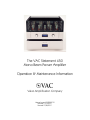
The VAC Statement 450
Mono Beam Power Amplifier
Operation & Maintenance Information
Valve Amplification Company
Manual issued 09/22/2010
Revised 01/19/2011
Revised 07/26/2011
CAUTION - SAFETY NOTICE
THE AMPLIFIER AND POWER SUPPLY CONTAIN NO USER SERVICEABLE PARTS. DO NOT REMOVE THE
BOTTOM PLATES OR CHASSIS COVERS. LETHAL VOLTAGES ARE PRESENT WITHIN THE CHASSIS. DO
NOT OPERATE THE UNITS IF THEY ARE WET.
VACUUM TUBES BECOME HOT ENOUGH TO CAUSE SERIOUS BURNS. NEVER TOUCH A TUBE WHEN
THE UNIT IS ON. IT MAY TAKE SEVERAL MINUTES FOR THE TUBES TO COOL DOWN AFTER THE UNIT
IS SWITCHED OFF. IT IS STRONGLY RECOMMENDED THAT THE TUBE COVERS BE LEFT IN PLACE AT ALL
TIMES.
THE TUBE COVERS WILL BECOME HOT IN NORMAL OPERATION. DO NOT SET OR SPRAY ANYTHING
ON THEM.
Never touch a tube if the glass is broken. The internal structures carry high voltage and could present
a serious, possibly lethal shock. If a tube breaks, unplug the amplifier and wait 30 minutes, then
remove the tube.
Keep flammable objects away from the amplifier.
DO NOT LEAVE THE AMPLIFIER UNATTENDED IN OPERATION.
THE AMPLIFIER IS HEAVY. IT IS ADVISABLE TO HAVE ASSISTANCE IN UNPACKING, MOVING, AND
SETTING UP. BE SURE TO USE PROPER LIFTING TECHNIQUES TO AVOID BACK STRAIN AND INJURY.
BE CERTAIN TO INSTALL IT IN A SECURE LOCATION FROM WHICH IT CAN NOT FALL OR TIP OVER.
1
INDEX
Introduction
Installation
Installing the front glass and top bars
Input connectors
Operation
Illuminated Logo
Installing New Output Tubes
Biasing & Checking Output Tube Condition
Replacement of Low Level Tubes
Care Of Chassis
Tips and Advice
Fuses
A Word About Tubes in General
Output Tubes
Low Level Tubes
Impedance Matching
Grounding
Tuning Your System
Specifications
Footnotes
Warranty & Registration Form
2
INTRODUCTION
The Statement 450 is a unique power amplifier, and the most powerful and detailed in VAC’s
history. Featuring a new direct-coupled input & driver circuit, extremely fast and vivid sound is
achieved from both single-ended and balanced sources.
The front panel attenuator may be selected for aid in balancing channels. It may also be used to trim
spectral balance when biamplifying.
The chassis is machined from thick aluminum, finished in a metallic base coat/clear coat finish.
The is designed not to the latest fad but to substance, for the highest possible sound quality. Time
spent familiarizing yourself with this manual will be well rewarded.
3
INSTALLATION
01)
004)
Place the power supply in its final location. It is quite heavy, and will become more so when
the amplifier is installed on top of it. Consider the location carefully, and use appropriate
help in lifting, etc., so as to avoid injury.
02)
Place one of the metal balls provided in each of the three cups on
the top of the power supply.
03)
Carefully place the amplifier chassis on top of the power supply,
taking care to align the balls on top of the power supply with the
cups on the bottom of the audio chassis.
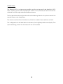
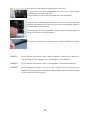
Install the vacuum tubes.
Each tube or its box has
a “V” number, which
corresponds to the
labels on the top plate of
the amplifier; these
indicate where each
tube should be installed.
Fit each tube into the
matching socket.
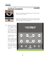
When inserting and
removing tubes, handle
them by their bases, not
by their glass bulbs.
Note that there is a
locator pin on the octal
(eight contact) tubes that
indicates proper
alignment.
4
05)
Carefully install the front glass and top rails (see detailed directions in the next section of this
manual). Take care not to chip or scratch the glass.
06)
Set the top switch to Balanced (for use with balanced sources on
XLR connector) or Single-ended (via RCA connector) as desired.
07)
Set the front panel SELECT switch fully
counterclockwise for full volume input, or clockwise
if you wish to attenuate volume using the front panel
VOLUME control.
08)
Install the input cable in the back panel jack that corresponds to the switch settings selected
above.
09)
Connect the speaker cables; the black lead goes to “-“ or “Ground”. The red lead goes to
“+” or “Positive”. Follow the label on the back of the amplifier for the impedance that best
matches your loudspeakers.
10)
Connect 12 volt trigger input cables into the appropriate sockets on the back panel if
desired; either will slave the off/on function to the external connection.
11)
Provide adequate ventilation - allow at least 3 inches above and to each side.
12)
Do not place in a completely enclosed cabinet. Do not stack other equipment on top of the
VAC unit.
13)
Do not operate on carpet or any other surface that might block air flow.
14)
The chassis and glass will become hot in normal use.
15)
The power supply may produce a small mechanical hum; therefore avoid placing the system
on any surface that could act as a sounding board, or at any location in the room that
corresponds to a resonance at your local power frequency (50 Hz. or 60 Hz.).
16)
Do not allow the chassis to touch any metal parts, such as the frame of an equipment rack.
This might create a parallel ground path that could degrade the sound of your system.
5
17)
Connect both of the cables between the power supply an d the audio chassis. Note that
each has a locating key and a locking collar. Be sure to insert the connector properly, and
fully tighten the locking collar.
18)
Connect the power cord to the power source indicated on the rear panel (will be either
100, 120, 220, or 240 volts AC). Voltage conversions must be done at the factory of by
an authorized VAC importer.
19)
Avoid power conditioners that float the ground pin.
20)
Power requirements are approximately 1000 watts. Pay close attention to power quality, and
be aware that different power cords can alter the sound.
21)
Check the bias settings of the output tubes when the unit is first
installed and whenever a tube is changed. It is also a good idea to
verify the settings periodically, such as once a week. Follow the bias
procedure outlined later in this manual.
22)
Note that there is a front panel TEST switch; this engages the eight
blue LEDs used for setting or monitoring the bias settings of the KT88
tubes. See Biasing & Checking Output Tube Condition for directions.
NOTE: Do not remove and connect input cables or speaker cables while is amplifier is running.
Doing so risks damage to your loudspeakers or the amplifier.
Do not operate the amplifier without a loudspeaker or load resistor attached.
Do not operate without the front glass and top rails in place.
Take care to keep everyone, especially children and pets, from being able to reach and
touch the tubes, which become extremely hot and cause serious injury.
Never touch a tube if the glass is broken. The internal structures carry high voltage and could
present a serious, possibly lethal shock. If a tube breaks, unplug the amplifier and wait 30
minutes, then remove the tube.
Keep flammable objects away from the amplifier.
6
INSTALLING THE FRONT GLASS AND TOP RAILS
Your amplifier has been shipped with the front glass and the top rails removed.
The following steps show how these are installed.
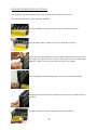
Lay the provided microfiber cloth on top of the fascia as shown.
Set the glass in place. Steady it with your hand; do not let go.
Insert one of the provided screw/cone washer assemblies into one of the
top holes in the glass. Start the screw, taking care that the threads align
properly. Tighten as much as you can using only your fingers.
Insert and tighten the remaining three screw/cone washer assemblies.
Using the provided Allen driver, tighten the four screws to a gentle but firm
pressure
Pull the microfiber cloth free, starting at one side as shown
7
The top tube cage bars have a spring pin in each end.
To install, place one of the spring pins into one of the small dimples
machined into one of the side rails.
In the Illustration, the pin has been located into the left side rail.
To complete the installation, press the bar in the direction of the pin already
inserted, and manoeuver the other end into the corresponding dimple in
the other side rail, then release.
In this illustration, the bar is pressed to the left, while the right spring pin is
set into the dimple in the right side rail.
The amount of protrusion of each pin may be adjusted slightly if needed.
REMINDER:
Do not remove and connect input cables or speaker cables while is amplifier is
running. Doing so risks damage to your loudspeakers or the amplifier.
REMINDER:
Do not operate the amplifier without a loudspeaker or load resistor attached.
REMINDER:
Provide adequate ventilation may not be safe. Failure to do so may shorten the
amplifier’s life, and may result in tube failures. Operating the amplifier on a thick carpet
will also cause this, and is not safe.
8
OPERATION
Sound will begin approximately 45 seconds after turn on.
As with all high fidelity products, the sound characteristic of the VAC changes somewhat as it warms
up. We advise against leaving the equipment on at all times for safety reasons, and because of the
attendant acceleration of output tube wear and power consumption. Life of the output tubes
averages 3,000 to 8,000 hours. For best tube life, turn the amplifier off when you are not listening.
Any time that the VAC Power Amplifier has not been used for a few weeks the sound may be
different. This is also normal for high resolution audio equipment. Optimum sound should return after
a few hours of operation, preferably with an audio signal.
Please note that although your VAC System has been run for 48 hours at the factory, the break-in
time of high resolution audio equipment is infuriatingly long. The Statement sound will continue to
season for approximately 200 hours. The early sound of the amplifier will be less extended, dynamic,
and coherent. Then the sound will improve noticeably, followed by a period of darker sound, finally
giving way to the desired musicality. Patience is a virtue.
Also be aware that many components display the need for a new break in period after being
transported in unheated cargo aircraft.
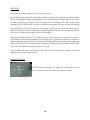
ILLUMINATED LOGO
The illumination of the front VAC logos may be dimmed or turned
off via a switch on the back panel of the power supply.
9
INSTALLING NEW OUTPUT TUBES
First, see the SAFETY NOTICE earlier in the manual.
Output tubes are type KT88. Replacement output tubes should be purchased from VAC. It is
desirable that tubes be in matched quartets for each channel, and be close to the "bogey" values
for the major parameters. Make certain that each tube fits firmly in its socket.
ALL POWER MUST BE OFF. Remove the top cage rods and the old tubes after they have cooled
down (THE CAGE RODS BECOME QUITE HOT IN NORMAL USE; TUBES BECOME HOT ENOUGH TO
CAUSE SERIOUS BURNS WHEN IN OPERATION AND MAY TAKE SEVERAL MINUTES TO COOL DOWN).
Install the new tubes firmly and fully in the sockets, observing that the tube will only fit into the socket
in one orientation, determined by the plastic “keyway” in the center of the base. Do not use
excessive force. Replace the top rods before operating the amplifier.
Adust the bias control(s) for the new tubes fully counterclockwise.
Switch on the amplifier and follow the bias procedure outlined later in this manual. Bias must be
checked and adjusted when the amplifier first turns on, at 60 seconds, 90 seconds, two minutes,
and five minutes. In the earliest checks, set the bias so that the meter read a bit to the left of center.
Final setting should be made after 15-30 minutes. Recheck new tubes daily for the first week.
Whenever a tube is changed, the bias settings must be checked and adjusted.
A slight violet glow in the tube is not cause for concern. If at any time the plate (the outermost metal
structure) of the output tubes begins to glow bright orange or red SWITCH OFF IMMEDIATELY. The
red glow indicates that the tube is "running away", being destroyed by conducting excessive
current. Tubes may run away for several reasons:
1)
2)
3)
The tube is not fully inserted in the socket.
The tube fits loosely in the socket and thus can not make correct contact. Such a tube is
unusable.
The tube is defective.
In the event that trouble is encountered check connections and/or try another tube. Stop if the
problem persists and consult with your dealer or VAC.
For further information, refer to Tips & Advice: Tubes in General and Tips & Advice: Output Tubes.
10
CHECKING OUTPUT TUBE CONDITION / OUTPUT TUBE BIAS ADJUSTMENT
Bias settings it should be checked when you install your amplifier and approximately once every
month thereafter. It must also be adjusted each time a tube is replaced.
The condition of the individual KT88 output tubes is checked using the TEST switch and eight built
in indicator lights (four on each side of the front panel, adjacent to the adjustment points..
If checking existing tubes, allow the amplifier to reach normal operating temperature (about ten
minutes of warmup should be sufficient). If installing new tubes, see INSTALLING NEW OUTPUT
TUBES.
To start, be certain to stop the music; no music should be playing during the adjustments. Next,
move the TEST switch to the right.
Start with the V06 BIAS control. Insert the supplied screwdriver (or a small flat bladed screwdriver)
into the adjustment control and turn in clockwise until the adjacent LED just lights; then turn it slightly
counterclockwise until the light goes out. Next, go to V07 BIAS and repeat the procedure, and so
on, through the V13 BIAS setting.
Because the adjustments can interact slightly, recheck all eight tubes, starting with V06.
The TEST switch may be turned off, or may remain on while playing music. If left on, the lights will
illuminate at low volume levels and appear to flash with the beat of the music. This is a simple way
to monitor bias in an ongoing fashion; the lights should be out between songs, and come on more
or less equally at low levels of music.
11
REPLACEMENT OF LOW LEVEL TUBES
All power must be switched off. Allow tubes to cool down. Remove the top glass cover. Remove
and replace with new tubes of the appropriate types. Note that these tubes have a central platic
shaft with a locator ridge on one side; this ridge must be aligned with the slot in the socket. Replace
the glass cover before operating the amplifier.
The exact characteristic of each tube and the relationship among the five 6SN7 is critical to the
optimal performance and best sound of your amplifier. Therefore we recommend obtaining
replacement tubes from VAC, specifying that they are for use in the Statement 450 amplifier.
For further information, refer to Tips & Advice: A Word About Tubes in General and Tips & Advice:
A Word About Low Level Tubes.
CARE OF CHASSIS
VAC chassis are machined aluminum for superior electromagnetic performance. The main chassis and
the fascia are finished in an acrylic lacquer, similar to fine automobile; similar care must be taken in
wiping or cleaning. THE AMP MUST BE SWITCHED OFF AND UNPLUGGED, and at no time may any
cleaning material be allowed to get into the tube sockets or jacks.
12
TIPS & ADVICE SECTION
Tips: Fuses
Your amplifier is designed to use “slow blow” type fuses. These are contained in the fuse drawer
built into the power receptacle.
In the fuse drawer are two fuses. The one furthers in is the active fuse. The one nearer to the outside
is a spare.
The fuse ratings are labeled on the back of the power supply. Be certain to use only the fuse rating
applicable to your local ac supply voltage.
With a high power amplifier, there can be an appreciable surge of current for a few milliseconds
when power is switched on. Over time, this can fatigue a fuse and cause it to fail at the instant that
power is applied. This may be considered normal.
In installations where the ac power is exceptionally stiff, you may find that the fuse blows every
second or third turn on. In such cases, please contact the factory for additional advice.
13
Tips: A Word About Tubes in General
It is true that each brand of tube sounds different in a particular high resolution circuit. This is because
no two manufacturers make a tube type in quite the same way, and the central tendencies of the
performance parameters will differ slightly with each maker. To emphasize the point, examine the
plate structure of any two 6SN7 from different manufacturers will probably find that they may not
even the same shape and size. (Be careful here, as often a tube is made by a firm other than
indicated on its label. In the heyday of tubes it was common to crossbrand between major labels,
such as GE and RCA. Today many labels do not manufacture their tubes at all, including Gold Aero
and RAM.)
This sonic variability may at first seem a liability, but further thought will reveal that it is an advantage,
just like the ability to adjust VTA on a tone arm. The owner of a tube amplifier can select those tubes
which sound like the real thing in his/her specific system. Of course, if the manufacturer you prefer
is rare you may want to purchase a few spare tubes for the future.
How long should tubes last? It has long been known in professional circles (and probably now
forgotten) that a tube such as the 12AX7 will display better performance characteristics after two
years of continual operation than when it was new. In normal use it is not unusual for a low level
tube to last 5 years or longer. Output tubes are another story, as they are continually providing
significant amounts of current. Here the sound is your best guide. Certainly a tube should be
replaced when its emission is significantly down or its transconductance is substantially out of
specification. In normal use, output tubes will last at least 2 years and perhaps more than 5 years.
It is normal to see a slight violet glow in a power tube such as a KT88. However, a vivid violet
indicates excess current flow through the tube and should be investigated.
VAC can test tubes for concerned customers.
14
Tips: Output Tubes
Your VAC Amplifier uses the KT88 kinkless tetrode. It is strongly recommended that replacement
tubes be purchased only from VAC. If, however, you want to customize the sound to your tastes,
be aware that as with interconnects and speaker cables, each tube manufacturer's KT88 tends to
have a distinct sound, as well as its own reliability profile.
Tips: Low Level Tubes
The Voltage Amplifier/Phase Splitter and driver tubes in the Statement is the 6SN7GT medium mu
octal twin triode. Your amplifier is fitted with the current production VAC Tested 6SN7 from China,
which we find superior to the NOS types we have tried. There are dozens of versions of this tube
available in new old stock (NOS) from a variety of sources. It would be impossible to characterize
them all.
The matches among the five 6SN7 are critical to the Statement 450's performance. Therefore we
recommend that replacement tubes be obtained in sets from VAC.
15
Tips: Impedance Matching
We strongly suggest that you experiment with the available impedance connections for the best
sonic match with your system. Since no loudspeaker represents an unchanging impedance at all
frequencies, it is impossible to assert with certainty which output tap is appropriate to use. In many
systems an amazing difference in sound will exist between the various impedance taps.
Since the impedance of most loudspeakers vary over a wide range experimentation is essential.
Most speakers have a rated impedance of 4 or 8 ohms. We recommend starting with the 8 ohm
connection; after you know the sound if that connection, try the 4 ohm connection. Choose the
connection that sounds best to your ears.
If you bi-wire your system (run separate speaker leads from the amplifier to the high and low
frequency transducers) you may discover that two different impedance taps work best.
Contrary to popular misconception, no power is lost due to unused output taps.
For more information consult VAC Technical Monograph 90-9, which may be viewed on our wesite
(http://www.vac-amps.com).
16
Tips: Audio Grounding
Systems incorporating single-ended interconnect cables (“RCA cables”) are prone to a problem
known as “ground looping”, which can result in extraneous hums and buzzes audible through the
loudspeaker. If this occurs in your system, you have to attempt to minimize the ground loop.
To minimize the buzz using the normal RCA input jack, there are several steps you can take:
1)
Use the shortest interconnects possible.
2)
Use interconnects with good shielding properties.
3)
Keep the audio cables as close together as possible.
4)
Keep the AC cords away from the audio cables.
5)
Try different ground settings on your preamplifier, if it has them. For example, the VAC
Signature, Phi, and Renaissance preamplifiers may be set to “ungrounded” or “XLR” audio
modes.
6)
The use of cheater plugs is not recommended and poses a safety hazard.
17
SPECIFICATIONS
The VAC Statement has been developed with the critical ear as the major arbiter of quality, with
both conventional and unique measurements providing insight and guidance as necessary. The lack
of emphasis on measurements is due to the fact that engineering's arsenal of equipment and
techniques do not operate on the pattern recognition principals that control human perception of
sound.
In the immortal words of Daniel von Recklinghausen, if it measures good and sounds bad, it is bad.
If it measures bad and sounds good, you've measured the wrong things.
For those concerned with test bench performance, the following describes typical measured
performance when operated at 120 VAC, 60 Hz.
•
•
•
•
•
•
•
•
•
•
•
•
•
450 watt mono amplifier with separate power supply
Gain: 39 dB, SE; 33 dB, balanced
Frequency response 4 Hz to 75 kHz
Power bandwidth 20 Hz to 70 kHz
Single-ended input via RCA jack, non-inverting
Balanced input via XLR jack, non-inverting relative to pin 2 ("pin 2 hot", traditional EIA/RCA
broadcast/recording standard); amp is fully balanced in this mode
12 volt triggers
Illuminated logo; may be switched off
Dimensions: 17.8" wide, 18.25" front to back (not including connectors), 9.75" high (audio
chassis), 128 lbs.
Dimensions: 17.8" wide, 18.25" front to back (not including connectors), 5.5" high (power
supply), 80 lbs.
8 x KT88, 5 x 6SN7
Detachable power cord, standard IEC power receptacle
May be factory configured for operation at 100, 120, 220, or 230/240 volt operation
18
WARRANTY
Your equipment is warranted for a period of thirty (30) days from the date of purchase. In addition, if the
registration form is received by VAC along with a copy of your sales receipt from an authorized VAC dealer
within this thirty days, the warranty will be extended to two (2) years (tubes excepted). This warranty applies
only to units sold in the United States of America through authorized VAC dealers and operated within the
United States by the original purchaser. It covers factory service and, within the continental U.S., standard
return shipping. For warranty information outside of the U.S. contact the importer of VAC equipment for your
country. Units sold outside of the U.S. should still be registered with VAC. It is the responsibility of the
customer and/or dealer to ensure suitability of this equipment for any particular application.
Your questions and comments are always welcome. Contact:
Valve Amplification Company
1911 East Avenue North
Sarasota, FL 34234
Telephone (941) 952 9695
Fax (941) 952 9691
[email protected]
_____________________________Detach and mail to the address above as soon as possible.____________________________
Statement 450 Registration Form
Name
________________________________________________________________________
Address
________________________________________________________________________
________________________________________________________________________
Telephone
_______/_______-_____________
e-mail __________________________________
Dealer name
________________________________ City ____________________________________
Salesperson
___________________ Purchase date
____________ Serial Number ________________
How did you first learn of VAC products? ____________________________________________________
What other brands/models did you consider? _________________________________________________
_____________________________________________________________________________________
What made you decide on the VAC? _______________________________________________________
_____________________________________________________________________________________
What else would you like us to know? _______________________________________________________
_____________________________________________________________________________________
_____________________________________________________________________________________
Optional:
What magazines do you read regularly?________________________________________________________
What are your hobbies (besides filling in warranty cards)? _______________________________________
What are your favorite types of music? ______________________________________________________
_____________________________________________________________________________________
On what format? (CD, LP, DVD, SACD, MP3, etc.) ______________________________________________