1
UEX/650 Upgrade Kit
For Model CP650
Installation Instructions
Issue 1
Part No. 91732
UEX/650 Upgrade Kit Installation
Dolby Laboratories, Inc.
Corporate Headquarters
Dolby Laboratories
100 Potrero Avenue
San Francisco, CA 94103-4813
Telephone 415-558-0200
Facsimile 415-863-1373
www.dolby.com
European Headquarters
Dolby Laboratories
Wootton Bassett
Wiltshire, SN4 8QJ, England
Telephone (44) 1793-842100
Facsimile (44) 1793-842101
DISCLAIMER OF WARRANTIES: Equipment manufactured by Dolby Laboratories is warranted against defects
in materials and workmanship for a period of one year from the date of purchase. All warranties, conditions or other
terms implied by statute are excluded to the fullest extent allowed by law.
LIMITATION OF LIABILITY: It is understood and agreed that Dolby Laboratories' liability whether in contract,
in tort, under any warranty, in negligence or otherwise shall not exceed the cost of repair or replacement of the
defective components and under no circumstances shall Dolby Laboratories be liable for incidental, special, direct,
indirect or consequential damages (including but not limited to damage to software or recorded audio or visual
material), or loss of use, revenue or profit even if Dolby Laboratories or its agents have been advised, orally or in
writing, of the possibility of such damages.
Dolby, the double-D symbol, and Surround EX are registered trademarks of Dolby Laboratories.
© 2000 Dolby Laboratories, Inc. All rights reserved.
Issue 1
S00/13304
Part No. 91732
ii
UEX/650 Upgrade Kit Installation
UEX/650 Upgrade Kit
Introduction
The UEX/650 upgrade kit converts a Dolby Model CP650D into a Model CP650 with
Dolby Digital Surround EX film soundtrack playback capability. See a detailed
description of the format at the end of this manual.
In addition, the kit adds digital AES/EBU input signal capability. This input
accommodates stereo PCM audio at sample rates of 48, 44.1, or 32 kHz. Jumpers can
be set to accommodate an S/PDIF input signal.
The signal input/output 25-pin D-connector is located on the rear panel of the CP650,
labeled "Option Card I/O. "
Note: Your CP650 must be capable of decoding Dolby Digital film soundtracks to play films with
Dolby Digital Surround EX soundtracks. If your cinema processor is a Model CP650SR, you must first
install a Cat. No. 773 Dolby Digital decoder board. The UD/650 upgrade kit is available for this
purpose.
The UEX/650 kit consists of:
• A Cat. No. 794 Dolby Digital Surround EX decoder with AES/EBU input
card
• Mounting hardware
Check CP650 Software Version
The CP650 operating system software must be version 1.1 or higher. With the CP650
operating normally, follow these steps:
Press the left menu button multiple times to step
through the menus to About this CP650.
Note: You can also press and hold the left menu button
while rotating the front panel fader knob clockwise to step
through the menu items.
About this CP650 is made up of three menu screens.
About this CP650:
System v.x.x.x.x
Cat.No.xyz installed
Cat.No.xyz installed
The first screen displays the version number of the
installed operating system software. If the version
reads v 1.0.x.x (x = any number), you must update
the software to version 1.1 or higher. Contact your
dealer.
Press the illuminated format button to return to the
top menu screen.
1
UEX/650 Upgrade Kit Installation
Handling PC Boards
Some steps in this upgrade involve handling printed circuit boards. Many components
on the PC boards are very sensitive to static electricity. These components can be
destroyed if static charge on your body discharges through the component. You do
not even have to touch the component to damage it. Before touching the components
or the printed circuit boards, ground yourself by rubbing the frame of the unit with
each hand or wearing an earthing strap.
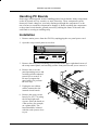
Installation
1. Remove mains power from the CP650 by unplugging the rear panel power cord.
2. Open the setup control panel access door.
12345678
Lt
Rt
Video Clamp RTA1 RTA2
SERIAL DATA
MIC MUX
SIGNAL
PRESENT
Lt
Rt
L
C
R
Ls
Rs
Sw
Mic Bypass
3. Remove the front-panel mounting screw located in the upper right-hand corner of
the setup control panel, and carefully pull the front panel toward you to remove it.
4. Remove the seven subpanel mounting screws and
carefully pull the subpanel
toward you to remove it.
Be sure to support the
panel while you perform
the next step.
5. Unplug the two ribbon
cables connected to the
internal circuit boards.
6. Remove the upper circuit
board (Cat. No. 774) using
the left and right card
ejectors. Place the board on
a flat surface (for example,
on a platter disk). The
board should be oriented
with the card ejectors close
to you.
2
UEX/650 Upgrade Kit Installation
MADE IN U.S.A/U.K.
J4
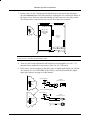
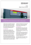
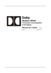
7. Remove the Cat. No. 794 upgrade kit board from its anti-static bag and plug it
into the left-hand side of the main board by aligning the two connectors shown in
the figure. Press down on each side making sure the connectors are fully seated.
The board can be oriented only one way for the connectors to match.
AES/EBU
S/PDIF
Cat. No. 794
Dolby Digital
Surround EX
board
Location of
Cat. No. 773
board
Note: The Cat. No. 794 will not function if it is installed in the right-hand location. This area is reserved
for the Cat. No. 773 Dolby Digital decoder board.
8. Turn over the board combination and install screws through the Cat. No. 774
board and into standoffs at each corner of the Cat. No. 794 board.
MADE IN U.S.A/U.K.
J4
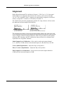
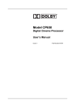
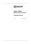
9. If necessary, set the jumpers to match the type of digital input signal you will use.
The jumpers are set to AES/EBU at the factory. A discussion about the digital
input types appears on page 6 of this manual.
OPTION CARD I/O
AES/EBU
Digital Output Source
2 1
AES/EBU
15
black
red
S/PDIF
2
3
1
MADE IN U.S.A/U.K.
J4
Cat. No. 794 board jumpers
OPTION CARD I/O
2 1
S/PDIF
Digital Output Source
AES/EBU
OR
S/PDIF
3
UEX/650 Upgrade Kit Installation
10. Reinstall the assembly into the CP650. Push the board in firmly until it is fully
seated.
11. Reinstall the two ribbon cables, inner panel, and front panel.
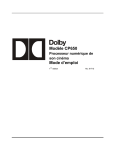
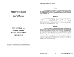
Power Amp Connections
With the Cat. No. 794 board installed, the CP650 outputs to all surround channels
appear at the Option I/O Card connector on the rear panel of the CP650. The Left
Surround and Right Surround channel output wiring must be moved from the Main
Audio Output connector to this connector. Do not use the Ls and Rs outputs on the
main audio output connector. Additionally, install the wiring for the new back
surround channel amplifiers.
OPTION CARD I/O
MAIN AUDIO OUTPUT
13
1
14
25
X
Left
Surround
Right
Surround
Signal
Gnd
Signal
Gnd
black
red
black
red
13
black
10
red
23
black
11
red
24
1
14
25
{
AES/EBU inputs
(see inputs diagram)
3
black
16
red
6
black
19
red
10
black
23
red
11
black
24
red
Signal
Gnd
Left
Back
Surround
black
red
Signal
Gnd
Right
Back
Surround
black
red
Signal
Gnd
black
red
Signal
Gnd
For unbalanced input amplifier
one channel shown
red
black
4
black
red
red
black
Signal
Gnd
Left
Surround
Right
Surround
UEX/650 Upgrade Kit Installation
Alignment
Dolby Digital Surround EX is defined as Format 13. The User 1 (U1) front panel
format button was assigned to this format at the factory, and is active when the
Cat. No. 794 is installed. If the U1 button was subsequently assigned to a different
format, reassign the U1 button (or U2 button) to Format 13.
The CP650 front-panel bar graph display and the PC setup software will now show
the additional surround outputs (Bsl and Bsr):
L C R Ls Rs SW Bsl Bsr
(Bsl level=Bsr level)
L C R Ls Rs SW Bsl Bsr
(Bsl level=Ls level), (Bsr level=Rs level)
The alignment procedure for the new surround outputs follows the same steps used
for the original Left Surround and Right Surround channels during the initial cinema
setup. Using the CP650 Installation Manual, follow the procedure for microphone
placement, RTA hookup, and SPL calibration; then perform level calibration and
equalization for all speaker channels:
Initial Output Level Calibration—Select and set each main output channel
(C, L, and R) to 85 dB, and set each surround output (Ls, Bsl, Bsr, Rs) to 82 dB.
Coarse (Bulk) Equalization—Adjust the EQ on all speakers.
Fine (1/3 octave) Equalization—Adjust the EQ on all speakers.
Final Output Level Calibration—Select and set each main output channel to
85 dB, and each surround output to 82 dB.
5
UEX/650 Upgrade Kit Installation
The AES/EBU Digital Input
With a Cat. No. 794 board installed, the CP650 is capable of handling input
bitstreams from a digital audio source. Possible digital sources include a CD player,
DVD player, satellite television receiver, HDTV receiver, or a HD video player.
Bitstream Format for the Digital Audio Input
The digital input on the Cat. No. 794 can accept a two-channel PCM (pulse code
modulated) bitstream. This is a single bitstream that contains the data for two
channels of PCM audio. It can handle sampling rates of up to 48 kHz with up to 24bit resolution. This bitstream format can be found on the digital output connector of a
CD player, DAT recorder, or any basic piece of digital audio equipment.
Interface Standards for Digital Audio
There are two interface types for digital inputs using copper conductors (non-optical
links): AES/EBU and S/PDIF. Even though there are differences in the connectors
used and the interface impedance, the format of the bitstream is generally the same.
One interface can be easily converted to the other if necessary.
AES/EBU STANDARD
The AES/EBU standard has been developed and adopted by professional audio
equipment manufacturers. The standard defines a balanced input (two conductors plus
shield) with a characteristic input impedance of 110 Ω. Equipment incorporating
AES/EBU digital outputs uses conventional-looking XLR connectors carrying digital
bitstreams instead of analog audio signals. Most professional audio equipment utilizes
this format because balanced operation yields superior noise immunity, just like
analog audio. Even in digital audio, noise-free signals are still very important. XLR
connectors have been standard on analog audio equipment, and this is another reason
for their adoption by the professional audio industry. The cable, however, is
specifically designed for digital audio use even though it appears to be the same as
that used for analog signals. Any professional audio equipment or broadcast supply
company can provide 110 Ω cable with connectors (or without, if you wish to
terminate them yourself). Use of cables not designed for 110 Ω digital transmission
will compromise the integrity of the bitstream and may create an unreliable link
between pieces of equipment, particularly with long cable runs.
S/PDIF
The S/PDIF interface, an "unofficial" standard, can be found on consumer
equipment. The interface uses a single-ended input (one center conductor plus shield)
with a characteristic input impedance of 75 Ω and peak-to-peak signal level of
0.5 V. An RCA (phono plug) connector is preferred for consumer equipment such as
CD and DVD players. Although S/PDIF-specific cables with connectors can be
purchased, good results can be obtained using high-quality 75 Ω video cables with the
appropriate connectors and/or adapters.
6
UEX/650 Upgrade Kit Installation
Professional video equipment uses a variation of this interface, where the P-P digital
audio signal is 1V. The decoding circuit handles both levels automatically. BNC
(“push and twist”) connectors are used for the digital audio signal on professional
video equipment. Like the use of XLR connectors on pro audio equipment, the
adoption of BNC connectors for pro video stems from their existing use for the video
signal. Again, you can use high-quality 75 ohm video cables with BNC connectors.
Alternatively, you can use high-quality RCA (phono plug) video cables with BNC
adapters since the cable and impedance are the same.
Multiple Sources—Conversion Between Interface Standards
If you intend to switch between multiple digital audio sources, DO NOT attempt to
convert a digital interface type by directly wiring an XLR connector to a BNC or
RCA plug. This will cause an impedance mismatch and signal reflections, resulting in
degradation of the digital waveform. It may seem to work, but the results will prove
unreliable and dropouts will occur.
With one digital audio input on the CP650, it may seem difficult to switch between
multiple units that use different digital output standards. It is actually easy to convert
from one interface to the other. A simple and economical method is to use inline
transformers. These devices perform the necessary impedance and connector
conversion between AES/EBU and S/PDIF signals. With the digital outputs of all
units converted to the same interface standard, a patchbay or a router/switcher can be
used for selecting which output is connected to the single digital input of the CP650.
The table below shows some examples of AES/EBU ↔ S/PDIF adapters. The
S/PDIF connector in these examples is a BNC. BNC-to-RCA adapters can be added
to connect to consumer S/PDIF outputs. The units listed below are of the “passive”
type.
Adapter Type
Female XLR 110 Ω In
to BNC Female 75 Ω Out
BNC Female 75 Ω In
to Male XLR 110 Ω Out
Neutrik
Canare
NA-BF
BCJ-XJ-TRA
NA-BM
BCJ-XP-TRA
Higher-priced units are available incorporating active circuitry that offer additional
features like multiple inputs, inputs for Toslink (fiber optic) digital connections, and
multiple outputs.
7
UEX/650 Upgrade Kit Installation
Assign Format 80
After the connections have been made, the digital input format (Format 80) must be
assigned to one of the user-definable format buttons U1, U2, or NS. Using the PC
setup software, select Format 80 from the pull-down list for the format button to be
assigned, or use the CP650 front-panel menu steps shown below.
Press the left menu button multiple times to
move to the User Format 1, 2, or NS menu.
This example shows the U2 button.
User Format 2
> Format xx
format name
User Format 2
>Format 80
Digital Input
OK
Rotate the fader knob to select Format 80 from
the list. "Digital Input" will display.
Press the OK button to save the assignment to
the Format button.
Saving Changes...
Press the illuminated Format button to return to
normal operation.
8
UEX/650 Upgrade Kit Installation
About Dolby Digital Surround EX
Dolby Digital Surround EX adds a third surround channel to digital film sound, a
concept first envisioned by sound designers at Lucasfilm’s Skywalker Sound post
production facility. Jointly developed by Dolby Laboratories and Lucasfilm THX ,
Dolby Digital Surround EX gives sound mixers a new level of creative freedom.
Dolby Digital Surround EX is fully compatible with all current 5.1 digital sound
formats and theatre systems. Prints that use it play normally with current systems, and
provide the extra surround channel when played using a CP650 cinema processor
equipped with the Cat. No. 794 board, or earlier Dolby cinema processors equipped
with the Dolby model SA10 adapter.
It has long been known that a center screen channel is necessary to ensure the precise
localization of front sounds for all viewers, including those seated off to the sides.
Dolby Digital Surround EX brings similar benefits to the surround sound field. With
Surround EX, a back surround channel is reproduced by the speaker array at the back
of the theatre, while left and right surround is reproduced by the side arrays. This
means that sounds can now be positioned behind the audience, opening the door to
exciting new effects, such as true 360° pans.
The back surround channel also makes front-to-back and back-to-front transitions
more realistic. Flyovers really seem to pass overhead, rather than down the sides of
the theatre. Even ambient sound reproduction is improved, being less affected by the
width of the theatre. Equally important, the new back surround channel assures that
even viewers seated close to the left or right of the theatre experience the total
surround ambience intended by the filmmaker.
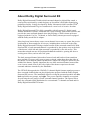
The UEX650 kit upgrades the CP650D 5.1-channel digital cinema sound processor to
three surround channels that can play digital prints prepared with the Dolby Digital
Surround EX process. The installation requires wiring the surround speakers into left,
back (split into two groups), and right. Two power amplifier channels are required
for powering the two groups of back surround channel speakers. The figures below
show the surround signal distribution for conventional 5.1-channel surround and for
Dolby Digital Surround EX format.
9
UEX/650 Upgrade Kit Installation
un
d
Bsl
su
ft
Ls
rro
Surround
amplifiers
Le
Dolby CP650
Bsr
Ls
Rs
d
un
ro
ur
ts
gh
Ri
10
Back surround left
Back surround right
Back surround left
Back surround right
Rs
Ls
Bsl
Bsr
Rs
Dolby Digital
5.1 mode
Bs
Rs
un
d
Bsr
Ls
Bsl
Bsr
Rs
su
ft
Le
Bsl
rro
Surround
amplifiers
Ls
Ls
d
un
ro
ur
ts
gh
Ri
U1
Dolby CP650
Rs
Dolby Digital
Surround EX mode
10
UEX/650 Upgrade Kit Installation
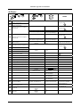
12345678
Setup Menu
DIP switch 6 UP
The Bsl and Bsr channels shown in italics are available only with Cat. No. 794 installed.
B-Chain:
menu
menu
OK
OK
Notes
Format and CP650 status
display
0–10
1
Calibrate SPL
45–108.5 dB
2
Output Levels Adjust (initial)
3
Digital Subwoofer Level
Adjust (initial)
4
Bulk EQ Adjust
Channel:
Level:
L, C, R, Ls, Bsl, Bsr,Rs
1–127 (0.3 dB steps)
Level:
Adjust fader. Standard
setting is 7.0.
Calibrates CP650 internal
SPL meter to agree with
auditorium sound level
meter reading.
Subwoofer level is set in
separate menu items.
1–127 (0.3 dB steps)
Channel:
Bass Adjust:
Treble Adjust:
Corner Frequency:
L, C, R, Ls, Bsl, Bsr, Rs
± 6 dB
± 10 dB
1, 2, 3, 4 kHz
Select channel:
L, C, R, Ls, Bsl, Bsr, Rs
B-Chain EQ Adjust
Set these before adjusting
B-Chain EQ.
(Fixed at 2 kHz for Ls, Bsl, Bsr,Rs)
OK
Press OK to start.
Select frequency band:
40 Hz–16 kHz
5
menu
OK
OK
+
=
Hold down middle button and turn the knob to adjust
level: ± 6 dB in the selected band.
6
Subwoofer EQ Adjust
7
Output Levels Adjust (final)
8
Digital Subwoofer Level
Adjust (final)
9
Optical Subwoofer Bandwidth
10
Optical Subwoofer Level
EQ center frequency:
EQ filter width (“Q”):
Level Cut:
Channel:
Level:
Level:
25–125 Hz
0.5, 1, 2, 4
0 to –12 dB
L, C, R, Ls, Bsl, Bsr, Rs
1–127 (0.3 dB steps)
TO EXIT: Press OK to
save, then press the Left
button to move back to the
channel selection menu.
Final level adjustment
after EQ.
1–127 (0.3 dB steps)
50 Hz / 100 Hz
50 Hz / 100 Hz
Level:
Polarity:
Center Noise:
1–127 (0.3 dB steps)
Normal / Inverse
on / off
Match SW to LF limit of
main screen speakers.
Perform final level
adjustment and polarity
check: center noise LF
output should decrease
when polarity is inverse.
System Software v1.1xx
11
UEX/650 Upgrade Kit Installation
A-Chain:
menu
menu
OK
OK
11
12
Notes
Automatic Optical Level
Adjust, Projector 1
Automatic Optical Level
Adjust, Projector 2
Run Cat. No. 69T test film
and press OK.
OK
.
Run Cat. No. 69T test film
and press OK.
Manual Optical Level Adjust,
Projector 1
13
OK
Left channel / Right channel
Adjust level of selected
cell: 0–63 (0.3 dB steps)
Run Cat. No. 69T test film
and press OK.
14
Manual Optical Level Adjust,
Projector 2
OK
Left channel / Right channel
Projector:
Channel:
Adjust level of selected
cell: 0–63 (0.3 dB steps)
P1 / P2
L/R
15
Optical Focus
16
Automatic Slit-loss Projector 1
Run Cat. No. 69P test film
and press OK.
17
18
19
Automatic Slit-loss Projector 2
OK
20
Bypass Level Adjust
21
22
23
24
25
26
27
28
Optical Surround Level Trim
Optical Surround Delay Adjust
Digital Surround Delay Adjust
Dolby Digital Reader delay
Nonsync 1 Level Adjust
Nonsync 2 Level Adjust
Mono Level Trim
Mono EQ adjust
29
Preset Fader Levels
30
User Format 1 select
31
User Format 2 select
32
Non-sync Format select
33
Reversion Mode
34
Noise Gating Active
35
Clock Set
36
Date Set
Manual Slit-loss Projector 1
Manual Slit-loss Projector 2
Channel:
Value:
Adjust lens for max HF.
L/R
1–127
OK
Format:
Fader level set:
Normal / No Reversion
Hour:
Minute:
Day:
Month:
Year:
–3 to +6 dB
20–150 ms
20–150 ms
16–512 perfs.
1–127
1–127
0 to –12 dB
LF
HF
1,4,5,10,11,U1,U2,NS
0–10 or None
Select Format to assign
to the U1 button.
Select Format to assign
to the U2 button.
Select Format to assign
to the NS button.
Normal / No Reversion
Set
Set
Set
Set
Set
12
Bypass / Normal
Run Cat. No. 151B test film
Recommended for test use
only. Resets to Normal
after powering on.
Special application. For
use with RT-60.
UEX/650 Upgrade Kit Installation
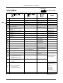
12345678
User Menu
DIP switch 6 DOWN
The options shown in bold are the default settings when the unit was shipped from the factory.
menu
menu
OK
OK
Notes
This is the top-level
menu display.
Format and CP650 status display
New
1
Fader Setting
Local/Auditorium
Local/Auditorium
2
Preset Fader Levels
Format:
Fader level set:
1,4,5,10,11,U1,U2,NS
0–10 or None
3
Auto Dolby Digital
Enabled/Disabled
Enabled/Disabled
4
Auto Digital Target
5
Automatic Optical Level Adjust
Projector 1
6
8
Automatic Optical Level Adjust
Projector 2
Manual Optical Level Adjust
Projector 1
Manual Optical Level Adjust
Projector 2
9
User Format 1 select
10
User Format 2 select
11
Nonsync Format select
12
Mute Fade-in Time
0.2–5 Seconds
13
Mute Fade-out Time
0.2–5 Seconds
14
Power-on Format select
15
Contrast Adjustment
Set the display contrast.
16
Event Log
Scroll up and down the
event listing.
7
17
18
Select Target Format:
Format 10 or Format 13.
Run Cat. No. 69T test film
Set level
Set level
Select Format to assign
to the U1 button
Select Format to assign
to the U2 button
Select Format to assign
to the NS button
Select from Format list or
select Last Format used.
About this CP650, Screen 3
•
Network address
•
Board version numbers
20
Return to the top-level menu display
Default is Format 13.
Default is Format 65.
Default is Format 60.
Select from Format list
or select Last Format
used.
Useful for telephone
discussions with your
service engineer.
About this CP650, Screen 1
•
Control software version
number
•
Optional boards installed
About this CP650, Screen 2
Software module version
•
numbers
19
Press OK to start.
Press OK to save.
Press OK to start.
Press OK to save.
Press OK to start.
Press OK to save.
Press OK to start.
Press OK to save.
The version numbers
are listed for each
board in the following
order:
Cat. No. 772
Cat. No. 773
Cat. No. 774
Cat. No. 777
Cat. No. 794
"x"= Board not installed
System Software v1.1xx
13