1
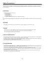
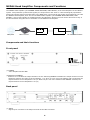
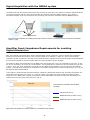
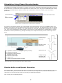
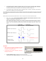
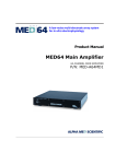
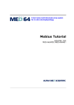
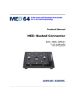
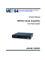
A low‐noise multi‐electrode array system for in vitro electrophysiology Product Manual MED64 Head Amplifier 64-CHANNEL HEAD AMPLIFIER P/N: MED-A64HE1 Information in this document is subject to change without notice.No part of this document may be reproduced or transmitted without the expressed written permission of Alpha MED Scientific Inc. While every precaution has been taken in the preparation of this document, the publisher and the authors assume no responsibility for errors or omissions, or for damages resulting from the use of information contained in this document or from the use of programs and source code that may accompany it. In no event shall the publisher and the author be liable for any loss of profit or any other commercial damage caused or alleged to have been caused directly or indirectly by this document. © 2011 Alpha MED Scientific Inc. All rights reserved Version: 1.10; September 1, 2011 Alpha MED Scientific Inc. Saito Bio-Incubator 209, 7-7-15, Saito-asagi, Ibaraki, Osaka 567-0085, Japan E-mail: [email protected] Website: http://www.med64.com Table of Contents Safety Precautions 2 MED64 Head Amplifier Components and Functions MED64 Head Amplifier Set-Up 4 6 Connecting the MED64 Main Amplifier to other Components 6 Signal Acquisition with the MED64 system 7 Amplifier Input-Impedance Requirements for avoiding Signal Attenuation Stimulation Using Planar Microelectrodes 8 Stimulus Artifacts and Biphasic Stimulation 8 Stimulus Current to be Applied to the Electrodes 10 Warranty 11 Specifications 11 1 7 Safety Precautions Before using this unit please read these operating instructions carefully. Take special care to follow the warnings indicated on the unit itself as well as the safety suggestions listed below. Keep these precautions at hand for future reference. Placement - Avoid placing the unit in areas of: • direct sunlight. • high temperature. • high humidity. • excessive vibration. • uneven surfaces. (Place the unit on a flat level surface.) Such conditions might damage the cabinet and/or other component parts and thereby shorten the unit's service life. Stacking - Never place heavy items on top of the unit, the DC power supply unit, or AC power cord. Voltage - Avoid the use of a “high voltage” AC power source. It is an extremely dangerous fire hazard. - A DC power source cannot be used. Be sure to check the power source carefully. - The working input voltage range is 90-264V AC. Power Cord Protection - Avoid using AC power cords with cuts, scratches, or poor connectors, as this may result in fire or electric shock. Excessive bending, pulling or slicing of the cord should also be avoided. - Do not pull on the cord when you are disconnecting the power. This could cause an electric shock. Grasp the plug firmly when you disconnect the power supply. - Never touch the plug with wet hands as a serious electric shock could result. Foreign Materials - Ensure that no foreign objects (e.g. - needles, coins, screwdrivers), accidentally fall into the unit. Otherwise, a serious electric shock, short circuit, or other malfunction could occur. - Be extremely careful about spilling water or liquid on or into the unit, as a fire, short circuit, or electric shock can also occur. Disconnect the power plug and contact your dealer immediately if this occurs. - Avoid spraying volatile chemicals (e.g.- insecticides, alcohol, paint thinner) on or into the unit. They contain flammable gases which can be ignited. - Insecticides, alcohol, paint thinner and similar chemicals should never be used to clean the unit. They can cause flaking or cloudiness to the cabinet finish. 2 Service - Never attempt to repair, disassemble or modify the unit if there seems to be a problem. A serious electric shock could result if you ignore this precautionary measure. - If a problem occurs during operation (smoke is detected, etc.) contact your dealer immediately. - Disconnect the power supply if the unit will not be used for a long time. Otherwise the unit’s lifetime could be shortened. Safety-related symbols used on equipment and documentation: Frame or chases TERMINAL Environmental Conditions - Indoor use. Altitude up to 2000 m. Temperature: 5 - 40 °C. Maximum relative humidity 80% for temperatures up to 31 °C decreasing linearly to 50% relative humidity at 40 °C. - Main supply voltage fluctuations not to exceed +/- 10% of the nominal voltage. Maintenance - Clean the cabinet, panel and controls with a soft cloth lightly moistened with mild detergent solution. - Do not use any type of abrasive pad, scouring power or solvent such as alcohol or benzene. - Supply voltage fluctuations must not to exceed +/- 10% of the nominal voltage. 3 MED64 Head Amplifier Components and Functions The MED64 Head Amplifier (64-CHANNEL HEAD AMPLIFIER, MED-A64HE1) is the head amplifier for the MED64 system. Filed potentials (extracellular signals) are acquired from the acute or cultured biological preparations placed onto the 64 planar microelectrodes in the MED probe. The acquired raw signals are amplified by x10 with the MED64 Head Amplifier, then sent to the MED64 Main Amplifier (64-CHANNEL MAIN AMPLIFIER, MEDA64MD1), where input signals are amplified further and digitized. Stimulus current can be delivered via any of the 64 electrodes using the built-in stimulator in the MED64 Head Amplifier. Digitizer Stimulator MED probe MED connector MED64 Head Amp. MED64 Main Amp. PC and Mobius software Components and their functions Front panel (2) (1) (1) POWER Turns amplifier ON and OFF. (2)STIMULUS CURRENT Selection of x2 doubles the output stimulus current. Selecting NORMAL maintains the output stimulus current amplitude equal to the value set in the software. (e.g. when 10 A is set in the software with x2 selected, the output stimulus current amplitude is 20 A. When 10 A is set in the software with NORMAL selected, the output stimulus current amplitude is 10 A) Back panel (1) (2) (7) (3) (4) (1) INPUT Signal input. Connects to the 68 pin terminal of the MED connector. 4 (5) (6) (2) OUTPUT Signal output. Connects to the [INPUT] terminal on the 64-CHANNEL MAIN AMPLIFIER (MED-A64MD1). (3) F1 STIMULUS INPUT Input for F1 stimulator. Connects to the [F1 STIMULUS OUTPUT] on the 64-CHANNEL MAIN AMPLIFIER (MEDA64MD1). (4) F2 STIMULUS INPUT Input for F2 stimulator. Connects to the [F2 STIMULUS OUTPUT] on the 64-CHANNEL MAIN AMPLIFIER (MEDA64MD1). (5) CONTROL INPUT Input for control of stimulus channels. Connects to the [CONTROL OUTPUT] on the 64-CHANNEL MAIN AMPLIFIER (MED-A64MD1). (6) SIGNAL GND Ground terminal for signals. Connect the grounding wire onto the MED connector cable here. (7) DC INPUT DC power supply cord inserts here. Accessories (1) (2) (1) DC Power supply unit -1unit(2) MED connector cable -1 unitConnects the [INPUT] terminal to the 68 pin terminal of the MED connector. 5 MED64 Head Amplifier Set-Up The MED64 system has several technical advantages due to the low-impedance platinum-black microelectrodes on the MED probe (typically 10 kΩ at 1kHz for 50 m electrodes). These include: 1. The system is more resistant to exogenous noise (e.g. hum noise). 2. Very low Johnson noise (baseline noise) as low as a few microvolts can be achieved. 3. The MED probe/connector can be physically separate from the amplifier (such as during longterm recordings in a humidified incubator). It is connected with a cable as long as 2m without noise or signal attenuation. The MED64 system does NOT usually require a Faraday cage or vibration isolation table necessary for conventional electrophysiology rigs. It is recommended that the MED64 system be installed on a STABLE TABLE such as lab bench using aluminium foil except when the system is used in conjunction with other equipment such as an incubator or microscope. Please refer to “MED64 Handbook Vol1 Hardware” for the installation and operation of the MED64 system. Connecting the MED64 Head Amplifier to other Components PC 64-CHANNEL MAIN AMPLIFIER 64-CHANNEL HEAD AMPLIFIER GND MED Connector 6 Signal Acquisition with the MED64 system The MED probe has 64 recording electrodes and 4 reference electrodes. The difference between potentials at the recording electrodes and the reference electrodes are measured with the MED64 system. Fig.1 shows a schematic diagram of the circuit between the recording and reference electrodes with the MED64 system. Reference electrodes Fig.1. Electrodes embedded on the MED probe (left) and the mechanism of recording of field potentials with the MED64 system (right). Amplifier Input-Impedance Requirements for avoiding Signal Attenuation One of the planar microelectrode's unique characteristics is that it forms an “electric double layer capacitor” between the electrode and solution. This “electric double layer capacitor” results in a rise in the electrode impedance at low frequencies. (See Fig.2) This detail should be noted because acquired signals are attenuated if the electrode impedance becomes higher than the input impedance of the amplifier. The platinum-black microelectrodes on the MED probe intrinsically have very low-impedances (at 1kHz, 10 kΩ for 50 m electrodes, 40 kΩ for 20 m electrodes). The impedances are small even at low frequencies (as seen in Fig.2). Thus, the input-impedance of 100 MΩ for the MED64 Head Amplifier is high enough for the MED64 system. Low-frequency signals such as fEPSPs or even slower signals such as from smooth muscle (0.1 Hz) can be acquired without attenuation. If 1Hz signal is acquired with flat ITO electrodes, signals are attenuated because the electrode impedances are larger than 100 MΩ (blue line in Fig. 2.). However, when 1Hz signals are acquired with the platinum-black electrode on the MED probe, signals are acquired without attenuation because the electrode impedances are smaller than 100 MΩ (green and red lines in Fig.2). Attenuation Input impedance of MED64 Head Amplifier (100 MΩ) ITO electrode (50 m) MED64 electrode (Pt. black. 20 m) MED64 electrode (Pt. black. 50 m) Fig.2. Electrode impedance and input impedance of the MED64 Head Amplifier. 7 Stimulation Using Planar Microelectrodes The MED64 Head Amplifier has a built-in 2 channel current-driven stimulator that enables stimulation via any of the 64 electrodes. The stimulus current amplitudes and channels are set in the [Acquire MED64R2 Data w/Stim] module in the MED64 Mobius software. Please refer to the Mobius Tutorial for setting up the stimulation parameters. Select stimulator Select stimulus electrodes Set stimulus waveform Fig.3. Mobius’ Control panel for setting stimulus parameter. Fig.4 shows a schematic diagram of the extracellular electrical stimulation circuit for the MED64 system. The stimulus current flows from the selected electrode to reference electrodes. The applied stimulus current charges the “electrical double-layer capacitor” (Ce) at the interface of electrode, subsequently changing the Ce voltage (Vc). This current modulates the field potential, which results in hyperpolarization or depolarization of cellular membranes. The field potentials (Vf) change according to the output current (Is) as seen on the right in the Fig.4. Stimulator output current (Is) Stimulator output voltage (Vs) Ce: Re: Rs: Is: Vs: Vc: Vf: Capacitance of electrical double-layer capacitor (electrode) Resistance of electrode Resistance of solution with slice Stimulator output current Stimulator output voltage Voltage of Ce Voltage of Rs (Voltage change in the field) Voltage of Ce (Vc) Voltage of Rs (Vf) (Changes in the field potentials) Fig.4. Stimulation using microelectrodes at the MED64 system. Stimulus Artifacts and Biphasic Stimulation During stimulation, signals (stimulus pulses) are recorded at recording channels (non-stimulated channels) due to crosstalk, causing "stimulus artifacts”. These stimulus artifacts can persist even after the stimulus pulse returns to zero and can interfere with the recording of real biological signals. This is mainly due to following factors: 8 1. The incoming stimulus artifacts’ amplitude often exceeds 5 mV, the maximum input voltage for the MED64 amplifier, causing a temporary saturation. The amplifier needs some time to recover. This delay becomes larger in proportion to the stimulation output voltage (Vs). 2. The electrode often needs longer time to discharge than to charge. This delay also becomes larger as the voltage of Ce (Vc) becomes larger. The duration of the stimulus artifact using the MED64 microelectrodes and amplifiers should be minimal with proper operation because both (Vs) and (Vc) levels are low due to the electrodes' low-impedance and highcapacitance. Please follow the directions described below in order to minimize the stimulus artifact duration. 1. Make sure to apply current-driven biphasic stimulation with identical durations for the negative and positive components as seen in Fig.5. When biphasic stimulation is applied, the electrode is charged and discharged quickly. However, when mono-phasic stimulation is applied the electrodes need longer time to discharge than to charge, which will dramatically prolong stimulus artifacts and damage electrodes. (Refer to the Fig.5.) Current-driven Biphasic stimulation Current-driven Mono-phasic stimulation Stimulator output current (Is) Stimulator output voltage (Vs) Voltage of Ce (Vc) Charge Discharge Prolonged stimulus artifact Voltage of Rs (Vf) -changes in the field- Fig.5. Biphasic stimulation and mono-phasic stimulation. CAUTION: • ONLY current-driven biphasic stimulation with identical durations for negative and positive is recommended for the MED64 system. • Do NOT apply mono-phasic stimulation, which will damage the electrode. Fig.6. Biphasic stimulation with identical durations for negative and positive. 2. Use the platinum-wire as additional reference electrodes. -Please refer to the “MED64 Handbook vol.1” for the use of platinum wire. 9 Stimulus Current to be Applied to Electrodes As described in the previous section, the applied current charges the electrical double-layer capacitor and causes the voltage (Vc) to change (Fig.7). When the voltage (Vc) rises beyond 1V, the electrode will undergo electrolysis and release H2 gas. This causes the stimulation efficiency to drop dramatically, introduces extremely large stimulus artifacts, harms cells, and damages the electrodes. Thus, the stimulus current (Is) should not go beyond this level. The (Vc) is defined by 0.1 ms (T) Vc = Is x t / Ce Vc with 100 A stimulation Vc: Is: T: Ce: 0.2V Vc with 500 A stimulation (electrolysis) 1V Voltage of Ce Stimulator output current Pulse duration Electrode capacitance (electrical double layer capacitor’s capacitance) The capacitance (Ce) of the MED64 microelectrode is as high as 50,000 pF for 50 x 50 m electrodes (22,000 pF for 20 x 20 m electrodes), allowing stimulation with current amplitudes up to 200 A for 0.2 msec (duration for each phase is 0.1 msec). DO NOT use stimulus current/duration parameters outside the shaded area in the Fig.7. Electrolysis Fig.7. Changes for Voltage of Ce (Vc) with different stimulus current amplitude. CAUTION: DO NOT use combinations of stimulus current & duration outside the shaded area in the Fig.8. Higher values might damage the electrodes. • The numerical value of this graph is based on “Single pulse stimulation”. If multi-paired stimulation with pulse interval shorter than 1 second is used, please decrease the stimulus current and duration values to 80% of the graph. Stimulus Current • 2 mA 200 A 20 A 2 A 0.01 ms 0.1 ms 1 ms 10 ms Duration for a phase Fig.8. Suggested stimulation parameters. 10 Warranty This product will be repaired with new or refurbished parts, free of charge, for one (1) year from the date of original purchase in the event of a defect in materials or workmanship. The product warranty covers failures due to defects in materials or workmanship which occur during normal use. It does NOT cover damage incurred during shipment or problems which are caused by products not supplied by Alpha MED Scientific. In addition, this warranty does not cover problems resulting from alteration, accident, misuse, neglect, faulty installation, maladjustment of user controls, improper maintenance, modifications or service by anyone other than AMS or damage attributable to acts of God. Specifications Amplifier Number of channels 64 Gain x 10 Bandwidth 0.1Hz - 100 kHz (+0dB to -3dB) Input impedance 100 MΩ Output impedance 10 MΩ Stimulator Number of channels 2 Output format Current-driven Maximum input voltage +/- 4V Maximum output current +/- 200 A General Power supply DC +/- 12V Weight 6.6 Kg Dimensions W430 x H74 x D437 mm Power supply unit Input AC 100-240 V (50-60 Hz) Output DC +/-12 V Specifications may not be satisfied depending upon the type of computer or operating environments used. Only for use in animal studies research. Specifications and external appearance are subject to change without notice. 11 September 1, 2011 Alpha MED Scientific Inc. Manufactured by Alpha MED Scientific Inc. ©2011 Alpha MED Scientific Inc. Saito Bio-Incubator 209, 7-7-15, Saito-asagi, Ibaraki, Osaka 567-0085, Japan Phone: +81-72-648-7973 FAX:+81-72-648-7974 http://www.med64.com [email protected]