1
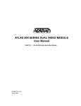
ISU 512
ISDN Service Unit
USER MANUAL
Part Number
ISU 512 (U Interface)
ISU 512 ST (ST Interface)
RS-530 to V.35 Adapter
RS-366 Y Cable
RJ-45 to DB-25 Adapter
61202.086L1-1B
September 1997
1202086L1
1202086L2
1200072L1
1200120L1
3196.ADPT003
Trademark:
5ESS is a registered trademark of AT&T
DMS-100 is a trademark of Northern Telecom, Inc.
ISU is a trademark of ADTRAN, Inc.
901 Explorer Boulevard
P.O. Box 140000
Huntsville, AL 35814-4000
Phone: (205) 963-8000
© 1997 ADTRAN, Inc.
All rights reserved.
Printed in USA.
FCC regulations require that the following information be provided in this manual:
1. This equipment complies with Part 68 of the FCC rules. On the bottom of the equipment housing is a label that shows the FCC registration number and Ringer Equivalence Number (REN) for this equipment. If requested, provide this information to
the telephone company.
2. If this equipment causes harm to the telephone network, the telephone company
may temporarily discontinue service. If possible, advance notification is given, otherwise, notification is given as soon as possible. The telephone company will advise
the customer of the right to file a complaint with the FCC.
3. The telephone company may make changes in its facilities, equipment, operations,
or procedures that could affect the proper operation of this equipment; advance notification and the opportunity to maintain uninterrupted service is given.
4. If experiencing difficulty with this equipment, please contact ADTRAN for repair
and warranty information. The telephone company may require this equipment to
be disconnected from the network until the problem is corrected, or it is certain the
equipment is not malfunctioning.
5. This unit contains no user serviceable parts.
6. An FCC compliant telephone cord with a modular plug is provided with this equipment. In addition, an FCC compliant cable appropriate for the dial backup option
ordered is provided with this equipment. This equipment is designed to be connected to the telephone network or premises wiring using an FCC compatible modular
jack, which is Part 68 compliant.
7. The following information may be required when applying to the local telephone
company for leased line facilities.
Service Type
ISDN
Digital Facility
Interface Code
021S5
Service Order Code
6.0F
Network Jacks
RJ-49C
FEDERAL COMMUNICATIONS COMMISSION
RADIO FREQUENCY INTERFERENCE STATEMENT
1202086L1
This equipment has been tested and found to comply with the limits for a Class B digital device,
pursuant to Part 15 of the FCC Rules. These limits are designed to provide reasonable protection against harmful interference in a residential environment. This equipment generates, uses,
and can radiate radio frequency energy and, if not installed and used in accordance with the instructions, may cause harmful interference to radio or TV reception, which can be determined
by turning the equipment off and on. The user is encouraged to try to correct the interference
by one or more of the following measures:
•
•
•
•
Reorient or relocate the receiving antenna.
Increase the separation between the equipment and receiver.
Connect the equipment into an outlet on a circuit different from that to which the
receiver is connected.
Consult the dealer or an experienced radio/TV technician for help.
Change or modifications to this unit not expressly approved by the party responsible
for compliance could void the user's authority to operate the equipment.
1202086L2
This equipment has been tested and found to comply with the limits for a Class A digital device,
pursuant to Part 15 of the FCC Rules. These limits are designed to provide reasonable protection against harmful interference in a residential environment. This equipment generates, uses,
and can radiate radio frequency energy and, if not installed and used in accordance with the instructions, may cause harmful interference to radio or TV reception, which can be determined
by turning the equipment off and on. The user is encouraged to try to correct the interference
by one or more of the following measures:
•
•
•
•
Reorient or relocate the receiving antenna.
Increase the separation between the equipment and receiver.
Connect the equipment into an outlet on a circuit different from that to which the
receiver is connected.
Consult the dealer or an experienced radio/TV technician for help.
Change or modifications to this unit not expressly approved by the party responsible
for compliance could void the user's authority to operate the equipment.
CANADIAN EMISSIONS REQUIREMENTS
1202086L1
This digital apparatus does not exceed the Class B limits for radio noise emissions from
digital apparatus as set out in the interference-causing equipment standard entitled
"Digital Apparatus," ICES-003 of the Department of Communications.
Cet appareil nuerique respecte les limites de bruits radioelectriques applicables aux
appareils numeriques de Class B prescrites dans la norme sur le materiel brouilleur:
"Appareils Numeriques," NMB-003 edictee par le ministre des Communications.
1202086L2
This digital apparatus does not exceed the Class A limits for radio noise emissions
from digital apparatus as set out in the interference-causing equipment standard entitled "Digital Apparatus," ICES-003 of the Department of Communications.
Cet appareil nuerique respecte les limites de bruits radioelectriques applicables aux
appareils numeriques de Class A prescrites dans la norme sur le materiel brouilleur:
"Appareils Numeriques," NMB-003 edictee par le ministre des Communications.
CANADIAN EQUIPMENT LIMITATIONS
Notice: The Canadian Industry and Science Canada label identifies certified equipment. This certification means that the equipment meets certain telecommunications
network protective, operational, and safety requirements. The Department does not
guarantee the equipment will operate to the user’s satisfaction.
Before installing this equipment, ensure that it is permissible to be connected to the facilities of the local telecommunications company. The equipment must also be installed using an acceptable method of connection. In some cases, the company’s inside
wiring associated with a single-line individual service may be extended by means of a
certified connector assembly (telephone extension cord). Compliance with the above
conditions may not prevent degradation of service in some situations.
Repairs to certified equipment should be made by an authorized Canadian maintenance facility designated by the supplier. Any repairs or alterations made by the user
to this equipment, or equipment malfunctions, may give the telecommunications company cause to request the user to disconnect the equipment.
Users should ensure for their own protection that the electrical ground connections of
the power utility, telephone lines, and internal metallic water pipe system, if present,
are connected together. This precaution may be particularly important in rural areas.
Users should not attempt to make such connections themselves, but should contact the
appropriate electric inspection authority, or an electrician, as appropriate.
The Load Number (LN) assigned to each terminal device denotes the percentage of the
total load to be connected to a telephone loop which is used by the device, to prevent
overloading. The termination on a loop may consist of any combination of devices
subject only to the requirement that the total of the Load Numbers of all devices does
not exceed 100.
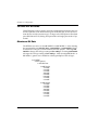
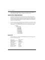
Quick Start Guide
Before configuring the ISUTM 512, the telephone service provider must supply
the switch type, service profile identifier (SPID), and local directory number
(LDN). For example, for one ISDN BRI 2B+D line:
Switch Type
SPID1
SPID2
LDN1
LDN2
National ISDN-1
20455512120100
20455512130100
5551212
5551213
To configure the ISU 512 from the front panel press Enter from the initial status screen and continue entering the appropriate numbers until the Switch
type, SPIDs and LDNs have been entered. (Note: Outside the U.S. and Canada,
you will not need to enter SPIDs.)
1=Netw. options
3=CONFIG 2=DTE options
3=BONDING setup
4=Quick setup
1=Dial Line
2=Leased Line
1=Switch type
2=Call type
3=Terminal ID
4=Dial options
5=Auto answer
6=Connect Timout
7=Call Screening
8=Passwords
9=Maint Setup
1=AT&T 5ESS
2=DMS-100
3=NATIONAL ISDN1
4=NEC
5=EuroISDN
1=Set SPID
2=Set LDN
Press Cancel to exit to the status screen and verify Ready conditions for each
BRI line configured. If the status screen reads SYNC, DOWN, TEI, or SPID,
either the configuration of the switch type and SPIDs are incorrect or there
may be a problem with the ISDN line or translations; see the chapter Troubleshooting. Outside of the U.S. and Canada, only the LDNs will need to be entered.
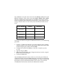
Service Profile/
Directory Number
Line
Interface
Maximum
Bandwidth
SPID1/LDN1
SPID2/LDN2
Line 1
128 kbps
SPID3/LDN3
SPID4/LDN4
Line 2
256 kbps
SPID5/LDN5
SPID6/LDN6
Line 3
384 kbps
SPID7/LDN7
SPID8/LDN8
Line 4
512 kbps
To configure the ISU 512 using the VT 100 terminal interface, use the following
procedure:
1.
2.
3.
4.
5.
Connect a VT 100 async terminal, or personal computer with a terminal
emulator package, to the Chain In port using an RJ-45 cable and the RJ-45
to DB-25 adapter (part number 3196.ADPT003).
Configure the terminal for 9600 bps, 8 data bits, 1 stop bit, no parity
(8/1/n).
Type !V and press Enter.
When the terminal displays the Configuration menu, enter the assigned
SPIDs, LDNs, and switch type.
Connect the ISDN lines.
Once the Ready condition has been achieved, a call can be placed from the
Configuration menu using the Ctl+D command, a test can be run using Ctl+T,
or the status of the line can be checked using Ctl+V. The status of the line and
the interface leads can be monitored while a call is active. Ctl+X exits the
VT 100 terminal and returns control to the Maintenance interface.
Table of Contents
Chapter 1. Understanding ISDN and the ISU 512 .....................................................
ISDN Overview ..................................................................................................................
Product Overview ..............................................................................................................
ISU 512 Interoperability ....................................................................................................
Recommended Operating Protocols................................................................................
1
1
1
4
5
Chapter 2. Ordering ISDN.............................................................................................. 7
Chapter 3. Installation ....................................................................................................
Installation...........................................................................................................................
Network Connection..........................................................................................................
DTE Data Connection ........................................................................................................
Dial Interface Connection..................................................................................................
Smart Dial String Formats ..........................................................................................
The Maintenance Interface................................................................................................
Software Update ..........................................................................................................
VT 100 Menu Interface ......................................................................................................
9
9
9
10
10
10
12
13
14
Chapter 4. Operation .......................................................................................................
Initial Self Test ....................................................................................................................
Menu Structure ...................................................................................................................
Main Menu ...................................................................................................................
Status Menu ..........................................................................................................
Test Menu..............................................................................................................
Configuration (CONFIG) Menu ........................................................................
Dial Menu..............................................................................................................
Basic Menu Traversal ..................................................................................................
Front Panel ..........................................................................................................................
LCD Window .................................................................................................
Enter ................................................................................................................
Numeric Keypad ...........................................................................................
Cancel..............................................................................................................
Up and Down Arrows ..................................................................................
LED Description ............................................................................................
19
19
20
20
20
20
21
21
21
22
23
23
23
23
23
23
Chapter 5. Configuration ................................................................................................
Using ISDN Basic Rate Switched Service .......................................................................
Configuring Network Options for Dial Operation .......................................................
Switch Type ..................................................................................................................
Call Type .......................................................................................................................
Speech ....................................................................................................................
Audio .....................................................................................................................
25
25
27
27
27
28
28
61202.086L1-1
ISU 512 User Manual
i
Table of Contents
Data 56 kbps..........................................................................................................
Data 64 kbps..........................................................................................................
Terminal Identification ...............................................................................................
Setting the SPID....................................................................................................
Setting the LDN....................................................................................................
Dial Options..................................................................................................................
Front Panel ............................................................................................................
RS-366 ....................................................................................................................
1 sec or EON...................................................................................................
2 sec or EON...................................................................................................
5 sec or EON (default)...................................................................................
10 sec or EON.................................................................................................
20 sec or EON.................................................................................................
Wait for EON .................................................................................................
Security ...........................................................................................................
V.25 bis...................................................................................................................
Auto Answer ................................................................................................................
Disabled.................................................................................................................
Enabled ..................................................................................................................
Dump all calls .......................................................................................................
Connect Timeout..........................................................................................................
Call Screening...............................................................................................................
Remote Access..............................................................................................................
Remote Download (RDL) ...................................................................................
Remote Supervision.............................................................................................
Maintenance Setup ......................................................................................................
Auto Traps......................................................................................................
ADLP Address ...............................................................................................
Port Mode .......................................................................................................
Call NumID ..................................................................................................................
Configuring the ISU 512 for Leased Digital Service......................................................
Clock Mode...................................................................................................................
Channel Rate ................................................................................................................
Test Remote ..................................................................................................................
Maintenance Setup ......................................................................................................
Auto Traps......................................................................................................
ADLP Address ...............................................................................................
Port Mode .......................................................................................................
Setting DTE Options ..........................................................................................................
Maximum Bit Rate .......................................................................................................
Connector Type............................................................................................................
RS-530 to V.35 Cable....................................................................................................
RS-366 Y Cable .............................................................................................................
CTS Options..................................................................................................................
CD Options ...................................................................................................................
DTR Options.................................................................................................................
DSR Options .................................................................................................................
BONDING setup ................................................................................................................
ii
61202.086L1-1 User Manual
28
28
29
29
30
30
31
31
31
31
32
32
32
32
32
32
33
33
33
33
34
34
35
35
36
37
37
37
37
38
39
39
40
41
41
41
41
41
42
42
43
43
43
44
44
44
45
46
61202.086L1-1
Table of Contents
TXINIT ..........................................................................................................................
TXFA..............................................................................................................................
TXADD01......................................................................................................................
TXDEQ ..........................................................................................................................
TANULL .......................................................................................................................
TCID ..............................................................................................................................
Call Stagger...................................................................................................................
Transparent 2x Clear Channel Protocol..........................................................................
Quick Setup Configuration...............................................................................................
Dial 512K.......................................................................................................................
Dial 384K.......................................................................................................................
Dial 448K.......................................................................................................................
Dial 336K.......................................................................................................................
Video 384K....................................................................................................................
Video 336K....................................................................................................................
Leased Master ..............................................................................................................
Leased Slave and Ldm SlvMstr .................................................................................
Dialing Options ..................................................................................................................
Hang Up Line...............................................................................................................
Dial Number.................................................................................................................
Redial Last Number ....................................................................................................
Answer Call..................................................................................................................
Dial Stored Number ....................................................................................................
Store/Review Number ...............................................................................................
Configuring the ISU 512 for V.25 bis In-band Dialing..................................................
46
47
47
47
47
48
48
49
50
50
51
51
51
52
52
52
53
54
54
54
54
54
54
55
56
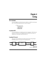
Chapter 6. Testing ............................................................................................................
Test Options ........................................................................................................................
Loopback DTE..............................................................................................................
Loopback Protocol.......................................................................................................
2047 Checker ................................................................................................................
Near-End Block Errors/Far-End Block Errors (NEBE/FEBE)..............................
Software Version..........................................................................................................
57
57
57
57
58
59
59
Chapter 7. Troubleshooting ...........................................................................................
If Self Test Fails...................................................................................................................
If an ISDN Network Line Reads Down ..........................................................................
If the Display Reads TEI1..................................................................................................
If the Display Reads TEI2..................................................................................................
If the Display Reads SPID{1,3,5, or 7}..............................................................................
If the Display Reads SPID{2,4,6, or 8}..............................................................................
61
61
61
63
64
65
65
Chapter 8. Specifications Summary..............................................................................
Specifications and Features...............................................................................................
Network Interface .........................................................................................
DTE Interface .................................................................................................
Dialing Selections ..........................................................................................
Data Rates.......................................................................................................
67
67
67
67
67
67
61202.086L1-1
ISU 512 User Manual
iii
Table of Contents
Rate Adaption ................................................................................................
Interoperability ..............................................................................................
D Channel Switch Compatibility ................................................................
B Channel Aggregation ................................................................................
Display ............................................................................................................
Environmental ...............................................................................................
Physical ...........................................................................................................
Power...............................................................................................................
67
67
68
68
68
68
68
68
Appendix A. Status Buffer Messages ........................................................................... 69
Appendix B. S-Register List ........................................................................................... 79
Appendix C. AT Commands ........................................................................................... 85
Appendix D. Pinouts ....................................................................................................... 89
Acronyms ............................................................................................................................ 97
Glossary............................................................................................................................... 99
Index .................................................................................................................................... 107
iv
61202.086L1-1 User Manual
61202.086L1-1
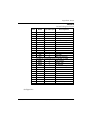
List of Figures
Figure 1-1:
Figure 1-2:
Figure 3-1:
Figure 3-2:
Figure 3-3:
Figure 3-4:
Figure 3-5:
Figure 3-6:
Figure 4-1:
Figure 4-2:
Figure 4-3:
Figure 5-1:
Figure 5-2:
Figure 5-3:
Figure 5-4:
Figure 5-5:
Figure 6-1:
Figure D-1:
Figure D-2:
Figure D-3:
Figure D-4:
Figure D-5:
Figure D-6:
61202.086L1-1
ISU 512 Rear Panel ..................................................................................... 2
ISU 512 (U interface) Applications .......................................................... 4
Maintenance Port VT 100 Menu ............................................................... 12
VT 100 Configuration Menu ..................................................................... 15
VT 100 Configuration Menu 2 .................................................................. 15
VT 100 Status Screen .................................................................................. 16
VT 100 Test Menu ....................................................................................... 16
VT 100 Dial Menu ....................................................................................... 17
Network Connection Status ...................................................................... 19
LCD Display of the Main Menu ............................................................... 20
ISU 512 Front View ..................................................................................... 22
Configuration Menu .................................................................................. 26
Dial Options Menu ..................................................................................... 31
Leased Line Menu ...................................................................................... 39
Limited Distance Modem Application .................................................... 40
Leased Application with Channel Banks ................................................ 40
ISU 512 Loopback Points ........................................................................... 57
EIA-232 to DB-25 Adapter Connector ..................................................... 89
RJ-45 ISDN Line Interface ......................................................................... 89
EIA-232, RS-366, and RS-530 Connector ................................................. 90
V.35 Connector ........................................................................................... 90
RS-366 Y Cable ............................................................................................ 95
RS-530 to V.35 Adapter Cable .................................................................. 95
ISU 512 User Manual
v
Table of Contents
vi
61202.086L1-1 User Manual
61202.086L1-1
List of Tables
Table 1-A:
Table C-A:
Table D-A:
Table D-B:
Table D-C:
Table D-D:
Table D-E:
Table D-F:
61202.086L1-1
ISU 512 Synchronous Rates ...................................................................... 5
AT Commands ............................................................................................ 85
Pinouts for Chain In and Chain Out Ports ............................................. 89
Pinouts for IFC RJ-45 Connectors ............................................................ 90
RS-366 Dialing Port Pinouts ...................................................................... 91
RS-530 Pinouts ............................................................................................ 92
V.35 Pinouts ................................................................................................ 93
RS-530-to-V.35 Adapter Cable Pinouts ................................................... 94
ISU 512 User Manual
vii
Table of Contents
viii
61202.086L1-1 User Manual
61202.086L1-1
Chapter 1
Understanding ISDN and the ISU 512
ISDN OVERVIEW
The Integrated Services Digital Network (ISDN) is a public or private switched
digital network. ISDN is an international standard for digital communications, allowing a full range of enhanced services supporting voice, data, and
image applications through standard interfaces over a single pair of telephone
wires. ISDN provides a means of integrating these services and modernizing
communication networks for information movement and management efficiency.
PRODUCT OVERVIEW
The ADTRAN ISDN Service Unit (ISU™) 512 is a stand alone device that connects data terminal equipment (DTE) to the ISDN network or to a leased digital network for data transmission. The ISU 512 is a basic inverse multiplexer
that provides cost-effective high-speed data transmission for a single application at rates up to 512 kbps.
From the network, ISDN is delivered by up to four 2-wire 2B1Q ISDN Basic
Rate U-interfaces which connect directly to the ISU 512 (U interface). ISDN
network termination is designed into the ISU 512, eliminating the need for separate NT1s. For network testing, the ISU 512 responds to NT1 test commands
from the telephone company central office (CO). The ISU 512 (ST interface) is
designed to work with the 4-wire AMI signals provided by an NT1.
61202.086L1-1
ISU 512 User Manual
1
Chapter 1: Understanding ISDN and the ISU 512
The ISU 512 transmits data over an RS-530 or V.35 interface, selectable from
the front panel. The ISU 512 performs at synchronous data transfer rates of 56
kbps to 512 kbps. At rates over 64 kbps, the BONDING Mode 1 inverse multiplexing protocol synchronizes data over up to eight 64 kbps B channels. By
supporting BONDING, the ISU 512 interoperates with other BONDING-compatible inverse multiplexers and ISDN terminal adapters. The ISU 512 is intended to support the transfer of data and images over ISDN.
The ISU 512 has four RJ-45 jacks available on the rear panel for network connection (see Figure 1-1).
#1
ISDN IFC
#2
#3
#4
RS530
CONTROL/
CHAIN PORT
IN
O
F
F
O
N
V.35
RS366 DIALING PORT
90-250 VAC
50/60HZ.15A
OUT
Figure 1-1
ISU 512 Rear Panel
The ISU 512 (U interface) also supports a leased digital connection that allows
data to be transferred at up to 512 kbps. This type of service is a permanent
connection between end points and is sometimes referred to as a leased connection, a dedicated connection, a nailed-up connection, a private circuit, or a
limited distance modem (LDM) connection. Leased connection or leased application is used in this manual to represent these types of services.
The ISU 512 can be configured using the front panel keypad, remotely over the
ISDN line, or using a VT 100 terminal operating at 9600 bps (8 data bits, 1 stop
bit, no parity). The VT 100 terminal interface is connected to the ISU 512
through the Chain In port on the rear of the unit. See the section VT 100 Menu
Interface in Chapter 3 for more information. The front panel keypad and the
terminal interface support test modes, test status, and dialing.
2
ISU 512 User Manual
61202.086L1-1
Chapter 1: Understanding ISDN and the ISU 512
Dialing from the ISU 512 is accomplished in a variety of ways:
•
•
•
•
•
•
Manually from the front panel keypad.
Manually from up to ten stored numbers.
Automatically through an RS-366 dialing port used in video conferencing
applications; a special RS-366 Y cable provides the two RS-366 interfaces
for this application (part number 1200120L1).
V.25 bis in-band dialing (used in applications such as LAN/WAN bridging).
Dialing while DTR is enabled. From Stored Number 0.
Dialing from the VT 100 terminal interface.
The ISU 512 (U interface) also supports dedicated leased 2B1Q services. This
provides a dedicated point-to-point service (as in a limited distance modem or
leased line application) with no dialing necessary.
The ISU 512 is designed to operate in a dual-port mode for videoconferencing
at 112/128 kbps. This allows end-to-end compatibility when communicating
with a video system that is utilizing two Switched 56 DSUs or a dual-port
ISDN terminal adaptor. For this application, 56/64 kbps is transmitted over
the V.35 interface and the RS-530 interface. An RS-530 to V.35 adapter (part
number 1200072L1) is available to provide the necessary V.35 interface for the
second port. Also, a special RS-366 Y cable (part number 1200120L1) provides
the two RS-366 interfaces for this application. For convenience in communicating with multiple video sites, the ISU 512 transparently switches between
the dual-port mode at 112/128 kbps and the single-port mode of 336/384 kbps
without user intervention and reconfiguration of the unit.
61202.086L1-1
ISU 512 User Manual
3
Chapter 1: Understanding ISDN and the ISU 512
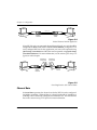
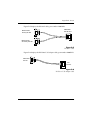
ISU 512 INTEROPERABILITY
Telephone networks are evolving from analog technologies to digital technologies such as ISDN. This transition is time-consuming and costly for telephone companies and upgrading all locations and facilities is a lengthy
process.
The ISU 512 bridges this transition by supporting communications with existing and future network services and equipment. The ISU 512 supports communications with Switched 56 (SW56) Service and Switched 56 DSUs (2-wire
and 4-wire) as well as various ISDN terminal adapters, ISDN terminal equipment, and BONDING Mode 1-compatible inverse multiplexers.
Figure 1-2 illustrates the ISU 512 (U interface) operation in various switched
network services and customer premises products.
Up to 4 BRI U-Interfaces
Videoconferencing
•Cost-effective video at 384 and
512 kbps
•Interoperates with
ISDN SWITCH
SW56 DSUs and dual port
ISDN TAs at 112/128 kbps
Up to 4 BRI U-Interfaces
RS
CS
TD
RD
ISU 512
ISU 512
CD
ISU 512
RS
CS
TD
RD
ENTER
CANCEL
SR
1
2
4
5
7
8
9
*
0
#
V.35
CD
TR
ENTER
1
4
5
7
8
9
CANCEL
*
0
#
SR
2
512 kbps
3
6
High-speed
workstation
ISDN SWITCH
Up to 4 BRI U-Interfaces
ISU 512
Disaster Recovery - T1 Backup
•TSU with Dial Backup
Module (DBU)
•Up to 512 kbps of backup ISDN SWITCH
bandwidth
RS-530/V.35
3
6
ISU 512
High-Speed File Transfers
•Image transfer
•Data backup
TR
ISU 512
RS
CS
TD
RD
CD
TR
ENTER
CANCEL
SR
1
2
4
5
7
8
9
*
0
#
3
6
T1
V.35
Bridge/Router
ADTRAN T1 DSU/CSU,
TSU 100, OR TSU 600
Figure 1-2
ISU 512 (U interface) Applications
The ISU 512 (ST interface) will also support these configurations but will require an
external NT1 for each BRI line.
4
ISU 512 User Manual
61202.086L1-1
Chapter 1: Understanding ISDN and the ISU 512
RECOMMENDED OPERATING PROTOCOLS
The ISU 512 supports BONDING Mode 1. For applications such as videoconferencing, in which the unit needs to interoperate with two SW56 lines or one
dual-port ISDN device, the 2 x clear channel protocol (dual-port mode) is used.
The ISU 512 automatically uses the 2 x clear channel protocol whenever it does
not find a BONDING partner. The first call (incoming or outgoing) connects
to the V.35 port in 2 x clear channel protocol. The second call (incoming or outgoing) connects to the RS-530 port. An RS-530 to V.35 cable (part number
1200072L1) may be required in some applications. Table 1-A lists the synchronous rates supported by the ISU 512, and the number of interfaces required
from the telephone company to accomplish the rate.
Table 1-A
ISU 512 Synchronous Rates
Rates
(Synchronous)
1x56K
1x64K
2x56K
2x64K
3x56K
3x64K
4x56K
4x64K
5x56K
5x64K
6x56K
6x64K
7x56K
7x64K
8x56K
8x64K
61202.086L1-1
Rate Adaption Method
BONDING/Clear Channel
BONDING/Clear Channel
BONDING/2 x Clear Channel Protocol
BONDING/2 x Clear Channel Protocol
BONDING
BONDING
BONDING
BONDING
BONDING
BONDING
BONDING
BONDING
BONDING
BONDING
BONDING
BONDING
ISU 512 User Manual
IFCs
Required
1
1
1
1
2
2
2
2
3
3
3
3
4
4
4
4
5
Chapter 1: Understanding ISDN and the ISU 512
6
ISU 512 User Manual
61202.086L1-1
Chapter 2
Ordering ISDN
ISDN is a complex service with many network options. Obtaining service
from the local telephone company and long distance providers can be complicated.
The following instructions only apply to North American switches.
In North America, the development of ISDN Ordering Codes (IOCs) simplifies
the process of ordering ISDN service. The ISDN Solutions Group, a consortium of ISDN equipment vendors, service providers, and Bellcore, established
these codes to represent predetermined line configurations for ISDN Basic
Rate service for specific applications.
ADTRAN and Bellcore have registered and tested eight generic IOCs. These
IOCs are supported by all major local exchange carriers as well as several independent carriers.
Capability S (previously Generic Data M) ordering code is recommended for
ISU 512 applications. It is the most feature-rich and supports most voice and
data applications. The voice capability is not necessary for operation of the
ISU 512; however it is useful in troubleshooting a misconfigured ISDN line. In
some areas, ISDN tariffs may warrant the use of ordering codes with less features. For example, in a particular region, there may be additional monthly expense associated with having voice service on each B channel. If you have a
data only application Capability R (previously Generic Data I) may be more
cost-effective. Each ISDN line provides 112/128 kbps of service. If 512 kbps is
needed for your application, order four ISDN lines. If 384 kbps is needed, only
order three ISDN lines, etc.
61202.086L1-1
ISU 512 User Manual
7
Chapter 2: Ordering ISDN
For more information regarding ordering ISDN, see the ADTRAN document
Ordering ISDN Service User Guide part number 60000.015-8, or contact the telephone company for alternative line configurations. The Ordering ISDN Service
User Guide is available on the ADTRAN home page at http://www.adtran.com
(go to the Service and Support page and then to the ISDN Information Desk)
or by calling ADTRAN at (205) 963-8000.
8
ISU 512 User Manual
61202.086L1-1
Chapter 3
Installation
INSTALLATION
After unpacking the unit, immediately inspect it for possible shipping damage. If damage is discovered, file a claim immediately with the shipping carrier, then contact ADTRAN Customer Service; see the inside back cover of this
manual for phone numbers.
NETWORK CONNECTION
The ISU 512 (U interface) supports either Dial or Leased operation. The ISU
512 (ST interface) supports only Dial operation. Four 8-pin RJ-45 modular
jacks on the rear panel of the ISU 512 allow connection to either network service.
Dial operation uses the ISDN Basic Rate interface and allows the ISU 512 to
dial out over the ISDN network. When used in this mode of operation, the
telephone company provided ISDN Basic Rate interface is connected to the RJ45 connectors marked ISDN IFC #1, #2, #3, and #4. Connect the Basic Rate interfaces to the ISU 512 in order, starting with ISDN IFC #1, until the maximum
number of lines (four) is reached.
The Leased mode of operation supports a dedicated 2B1Q data service at rates
of up to 512 kbps by using nailed up circuits or a permanent connection between end points. This could be a limited distance modem or point-to-point
connection.
See the appendix Pinouts for network connection pin assignments.
61202.086L1-1
ISU 512 User Manual
9
Chapter 3: Installation
DTE DATA CONNECTION
Data terminal equipment (DTE) is connected to the ISU 512 by using the V.35
interface, and/or the RS-530 interface on the rear panel of the ISU 512. The
maximum cable lengths recommended are 50 feet for the RS-530 interface, or
150 feet for the V.35 interface. The pin assignments for the DTE interfaces are
shown in the appendix Pinouts.
The RS-530 interface and the V.35 interface support data rates up to 512 kbps.
The DTE rate can be configured from the front panel or the VT 100 terminal
interface of the ISU 512. See the chapter Configuration for information regarding configuring the ISU 512 with the appropriate data rates for the application.
To prevent possible radio frequency interference emissions, shielded cables are required.
DIAL INTERFACE CONNECTION
If out-of-band RS-366 dialing is required for applications such as video conferencing, the dialing interface of the host DTE should be connected to the port
labeled RS366 DIALING PORT. A special RS-366 Y cable provides the two
RS-366 interfaces required for dual-port videoconferencing applications (part
number 1200120L1). For pin assignment information for the RS-366 connector
and the RS-366 Y cable, see the appendix Pinouts.
Smart Dial String Formats
The ISU 512 accepts changes to Call Type and Channel Rate by using suffix
commands appended to the end of the dial string. The following string format
is used.
dial string
call type
channel rate
XXX XXX XXXX #C #R
Where #C changes the Call Type as follows:
1 = Speech
2 = Audio
3 = 56K Data
4 = 64K Data
10
ISU 512 User Manual
61202.086L1-1
Chapter 3: Installation
Where #R changes the Channel Rate (number of ISDN B channels) as follows:
0 = (2x56k and 2x64k) 2 x Clear Channel Protocol
1 = 1 B Channel (1x56k, 1x64k) BONDING Mode 1
2 = 2 B Channels (2x56k, 2x64k) BONDING Mode 1
3 = 3 B Channels (3x56k, 3x64k) BONDING Mode 1
4 = 4 B Channels (4x56k, 4x64k) BONDING Mode 1
5 = 5 B Channels (5x56k, 5x64k) BONDING Mode 1
6 = 6 B Channels (6x56k, 6x64k) BONDING Mode 1
7 = 7 B Channels (7x56k, 7x64k) BONDING Mode 1
8 = 8 B Channels (8x56k, 8x64k) BONDING Mode 1
The following are dialing examples:
Two-port call using 64k call type (2x64)
Two-port call using 56k call type (2x56k)
BONDING 384k using 64k call type (6x64k)
BONDING 336k using 56k call type (6x56k)
BONDING 256k using 64k call type (4x64k)
7082906055#4#0
7082906055#3#0
7082906055#4#6
7082906055#3#6
7082906055#4#4
If no suffix is used, the call is placed using the values configured for the ISU
512. For example, if the ISU 512 is configured for 384K, the dial string
7082906055 is the same as 7082906055#4#6.
If the Channel Rate suffix is used, the Call Type suffix is required. However,
the Channel Rate is not required to make changes to the Call Type. For example, if the ISU 512 is configured for 384K Call Type, only the #3 suffix is required to change the Call Type to 336K. The dial string 7082906055#3 is the
same as 7082906055#3#6.
When placing non-bonded two channel calls, the originating end must use
both the Call Type and Channel Rate suffixes; otherwise, the ISU 512 attempts
to negotiate BONDING before using 2 x Clear Channel protocol. This works
for Ascend and ADTRAN; Promptus hangs the call up. Using the Channel
Rate suffix #0 causes the ISU 512 to omit BONDING negotiation and use only
2 x Clear Channel protocol; this succeeds with all vendors.
61202.086L1-1
ISU 512 User Manual
11
Chapter 3: Installation
THE MAINTENANCE INTERFACE
The Maintenance Interface is available at 9600 bps, 8 data bits, no parity,
through the CHAIN IN port. See the appendix Pinouts for the Chain In port
pinout. The VT 100 terminal or null modem can be connected to the Chain In
port using the RJ-45 to DB-25 adapter (part number 3196.ADPT003) and the
RJ-45 to RJ-45 cable provided with the unit. The port contains transmit and receive data (EIA-232 compatible). This interface can be used to set internal Sregisters, dial ISDN connections, and disconnect calls. This port also allows
ADTRAN Technical Support personnel to retrieve vital information from the
unit if a problem is encountered during initial configuration of the ISU 512.
Most problems can be solved without resorting to this port for assistance.
The terminal should be set for 9600 bps, 8 data bits, and no parity. The maintenance port is activated by typing !V at the - - 512-> prompt.
There are four maintenance port commands available to display and clear the
status buffer, display the internal print buffer, loop status and help screen; see
Figure 3-1.
Figure 3-1
Maintenance Port VT 100 Menu
Plugging the RJ-45 cable from the telephone service provider into the Chain In or
Chain Out ports could cause damage to the ISU 512.
12
ISU 512 User Manual
61202.086L1-1
Chapter 3: Installation
Software Update
There are two methods available for updating ISU 512 software. The local
method involves using the Chain In port and is described in this section. The
remote method involves transmitting smart dial strings over a dial-up connection and is described in the section Remote Access of the chapter Configuration.
The ISU 512 contains Flash memory allowing the software to be updated using
the Chain In port. The ISU 512 software can be updated using any PC with an
EIA-232 COM port and a communication package supporting XMODEM protocol. Download speed and format are set to 38400 bps, 8 data bits, 1 stop bit,
no parity, and no flow control. After obtaining a new code file with the extension (.bin) from Technical Support (see the inside back cover), use the following procedure to update the software:
Ensure the terminal software package has flow control turned off.
1.
2.
3.
4.
5.
6.
Power the ISU 512 Off.
Connect the PC to the ISU 512 using an RJ-45 to DB-25 adapter (part number 3196.ADPT003) connected from the Chain In (RJ-45) connector on the
rear panel of the ISU 512 to the COM port on the PC. See the appendix Pinouts for a diagram of this cable.
Start the communication package, supporting XMODEM protocol, on the
PC. Set for Connect Local if necessary.
Set the COM port for 38400, 8, 1, n and no flow control.
Start the XMODEM protocol and transfer the .bin file to the ISU 512.
XMODEM should come on-line and wait for the far end to connect. The
far end in this case is the ISU 512.
Power On the ISU 512 while holding the Up Arrow. Holding the Up Arrow during self test initiates the software update.
Do not power Off the unit during the loading process. After the load is complete the
ISU 512 restarts itself. If power is lost during the software load, repeat the procedure
from the beginning.
It may be necessary to set the communications software to Connect Local, which sets
the session up to ignore carrier detect on the EIA-232 port and transfer files anyway.
61202.086L1-1
ISU 512 User Manual
13
Chapter 3: Installation
VT 100 MENU INTERFACE
The VT 100 menu interface can be used by connecting a VT 100 compatible terminal to the Chain In port on the back of the ISU 512. The VT 100 terminal (or
PC running terminal emulation software) is connected to the Chain In port using the RJ-45 to DB-25 adapter (part number 3196.ADPT003) and the RJ-45 to
RJ-45 cable provided with the unit. See the appendix Pinouts for the Chain In
port pinout information. The Chain In port is a DCE connector that contains
transmit (Tx) and receive (Rx) data (EIA-232 compatible signals) and system
ground. The terminal should be set for 9600 bps, 8 data bits, 1 stop bit, and
no parity. The VT 100 menu is activated by typing !V at the - - 512-> prompt.
Remote access to the ISU 512 is supported through the Chain In port by use of
a null modem cable connected to a modem (DCE interface). Use the RJ-45 to
DB-25 adapter (part number 3196.ADPT003) and the RJ-45 to RJ-45 cable to
connect the modem to the Chain In port. Ensure that the modem is set for Ignore DTR and Auto Answer is enabled.
The VT 100 menu interface can be used instead of the front panel to set options
and dial up ISDN connections. Test functions and unit status can also be obtained by using the VT 100 menu interface. To select a function, press the number corresponding to the function and press Enter.
The bottom of each screen displays commands available for accessing other
menus or exiting the VT 100 interface. These commands require the use of the
Control key (Ctl) and a letter.
The first screen displayed is the Configuration Screen (Ctl+C). From this
screen ISU 512 options are configured; see Figure 3-2. Selecting option 32)MORE- displays a second Configuration screen with additional setup options;
see Figure 3-3.
The Status Screen (Ctl+V) is used to view the current status of the ISU 512; see
Figure 3-4. The Test Screen (Ctl+T) activates DTE and protocol loopbacks; see
Figure 3-5. The Dial Screen (Ctl+D) is used to dial and terminate calls; see Figure 3-6.
Select Ctl+X to exit the VT 100 menu interface and return control to the Maintenance interface. See the section The Maintenance Interface for more information.
14
ISU 512 User Manual
61202.086L1-1
Chapter 3: Installation
Figure 3-2
VT 100 Configuration Menu
Figure 3-3
VT 100 Configuration Menu 2
61202.086L1-1
ISU 512 User Manual
15
Chapter 3: Installation
Figure 3-4
VT 100 Status Screen
Figure 3-5
VT 100 Test Menu
16
ISU 512 User Manual
61202.086L1-1
Chapter 3: Installation
Figure 3-6
VT 100 Dial Menu
61202.086L1-1
ISU 512 User Manual
17
Chapter 3: Installation
18
ISU 512 User Manual
61202.086L1-1
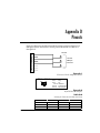
Chapter 4
Operation
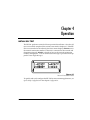
INITIAL SELF TEST
The ISU 512 performs an initial self test upon initial installation. Once the self
test is successfully completed, the current status mode is displayed. If the ISU
512 is not connected to the network, the Status menu displays DOWN next to
the network connection number. If the unit is connected to the network and
functioning properly, READY is displayed next to the network connection
number; see Figure 4-1. A list of current status messages is provided in the appendix Status Buffer Messages.
Figure 4-1
Network Connection Status
To quickly and easily configure the ISU 512 for most common applications, see
Quick Setup Configuration in the chapter Configuration.
61202.086L1-1
ISU 512 User Manual
19
Chapter 4: Operation
MENU STRUCTURE
The ISU 512 uses a multilevel menu approach to access its many features. All
menu operations are displayed in the LCD window or are available from the
VT 100 terminal interface.
The opening menu is the access point to all other operations. There are four
Main menu branches: Status, Test, Configuration, and Dial.
Each Main menu item has several functions and submenus to identify and access specific parameters.
Main Menu
There are four branches of the main menu as shown in Figure 4-2.
Figure 4-2
LCD Display of the Main Menu
Status Menu
Selecting 1=STATUS from the top of the menu tree displays the contents of
the status buffer. The Up and Down arrows allow the viewing of the last
twenty status messages generated during operation of the unit. (An explanation of Status Buffer Messages can be found in the appendix, Status Buffer Messages.) Pressing 0 clears the buffer. Pressing Cancel returns to the top of the
menu.
Test Menu
Test controls local and remote testing.
20
ISU 512 User Manual
61202.086L1-1
Chapter 4: Operation
Configuration (CONFIG) Menu
Configuration selects network and DTE operating parameters.
Dial Menu
Dial provides manual dialing functions. Key in a number to dial or select one
of the ten stored numbers.
Basic Menu Traversal
Four function keys on the left side of the ISU 512 keypad allow the various
menu branches to be entered, exited, and scrolled through. The four function
keys are defined below:
Enter
Up Arrow
Down Arrow
Cancel
Selects flashing menu item.
Scrolls up the menu tree.
Scrolls down the menu tree.
Exits (back one level) from the current branch
of the menu.
Function keys are represented in bold, initially capitalized text. Selectable menu items
and messages displayed on the LCD are represented in bold type as they appear on the
LCD.
To choose an item, press the corresponding number on the keypad. The item
flashes on and off to show it is the currently selected (active) choice. Pressing
either the Up or Down Arrow scrolls through the available menu items. Press
Enter to select the item.
When a command is selected, the ISU 512 issues one of two commands:
Command Accepted Indicates a successful command processed
by the ISU 512.
Command Rejected
Indicates improper configuration attempted. The command is not executed and no
configuration change occurs.
The following example illustrates how to select ISU 512 Dial Options:
1.
2.
61202.086L1-1
Select Configuration (CONFIG) by pressing 3, then press Enter.
Use the Up and Down Arrows to view submenu items.
ISU 512 User Manual
21
Chapter 4: Operation
3.
4.
Choose an item on the submenu such asNetwork Options (Netw. options)
by pressing the corresponding number followed by Enter.
To select Dial Line options, press 1, then press Enter.
The menu path follows:
3=CONFIG
1=Netw. options
1=Dial Line
4=Dial Options
It is important to note that some features in the ISU 512 do not immediately
take effect upon selection. This prevents unintentional reconfiguration of the
ISU 512 during an active call. Items such as Leased/Dial line, SPID/LDN, and
ISDN switch type, take effect only when the ISU 512 is powered up or the Basic Rate interface is bounced (line broken and restored). Also, items such as
Bit Rate, BONDING setup, and Call type take effect only at the beginning of
a new call.
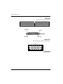
FRONT PANEL
Figure 4-3 shows the ISU 512 front panel.
ISU 512
ENTER
A
1
B
2
C
3
D
4
E
5
F
6
7
8
SHIFT
CANCEL
*
9
QUICK
0
#
Figure 4-3
ISU 512 Front View
The ISU 512 front panel consists of a 2-line, 16-character LCD display, seven
LED indicators, and a 16-button keypad. This allows for configuring, dialing,
testing, and monitoring the unit without data terminal or test equipment.
22
ISU 512 User Manual
61202.086L1-1
Chapter 4: Operation
LCD Window
Displays menu items and messages in 2 lines by 16 characters.
Enter
Selects active menu items. To select a menu item, press the number of the item
to activate. When the menu item is flashing, press Enter to select it. A submenu item is invoked or a configuration parameter is set.
Numeric Keypad
The numeric keypad contains the numbers 0 through 9, which are used to activate menu items and enter parameters.
Cancel
Stops the current activity and returns to the previous menu. Repeat until the
desired menu level is reached. When a submenu item is displayed, press Cancel to exit the current display and return to the previous menu. Repeat until
the desired menu level is reached.
Up and Down Arrows
Up and Down Arrows scroll through the submenu items available in the current menu. Submenu items display two at a time in a circular or wrapping
fashion. When the submenu items are scrolled, they continuously appear
from beginning to end in a forward (Down Arrow) or reverse (Up Arrow) pattern.
LED Description
The LED indicators monitor data flow and display the status of key DTE interface leads described as follows:
RS
CS
TD
RD
CD
TR
SR
61202.086L1-1
Request to send.
Clear to send. Indicates the ISU 512 is ready to transmit.
Transmit data. On when the DTE is transmitting to the
ISU 512.
Receive data. On when the ISU 512 is receiving data from
the far end.
Carrier detect. Indicates the ISU 512 is connected to a remote unit.
Terminal ready from DTE. On when DTR is active at DTE
interface.
Data set ready.
ISU 512 User Manual
23
Chapter 4: Operation
24
ISU 512 User Manual
61202.086L1-1
Chapter 5
Configuration
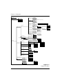
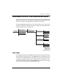
USING ISDN BASIC RATE SWITCHED SERVICE
This section explains how to configure the ISU 512 when using ISDN Basic
Rate switched service. Figure 5-1 illustrates the entire Configuration branch of
the menu tree.
61202.086L1-1
ISU 512 User Manual
25
Chapter 5: Configuration
1=STATUS
2=TEST
1=Loopback DTE
2=Loopback Proto
3=2047 Checker
4=NEBE/FEBE
5=Software Ver
1=Switch type
1=AT&T 5ESS
2= DMS-100
3=National ISDN1
4=NEC Switch
5=EuroISDN (only available on the ISU 512 ST)
2=Call type
1=Speech
2=Audio
3=Data 56Kbps
4=Data 64Kbps
3=Terminal ID
Set SPID
<Use Up and Down keys to select SPID 1 to 8>
Set LDN
<Use Up and Down keys to select LDN 1 to 8>
4=Dial options
1=Dial Line
1=Front Panel
2=RS-366
3=V.25
1=Disabled
2=Enabled
3=Dump all calls
6=Connect Timout
7=Call Screening
1=Answer any
2=ansr if SNO…9
8=Passwords
1=SPV Password
2=RDL Password
1=15 sec
2=30 sec (def)
3=1 minute
4=2 minute
5=4 minute
3=S Bus Termination
1=Enabled
ISU 512 ST only
2=Disabled
0=Call NumID
1=Enabled
2=Disabled
1=Clock mode
1=Slave
2=Slave (Master)
3=Master
2=Channel rate
3=Test Remote
1=Max Bit Rate
2=DTE options
1=64K Mode 1
2=56K Mode 1
2=Connector Type
3=530-V35 Cable
4=RS366-Y Cable
5=CTS Option
1=RS-530
2=V.35
1=Enable
2=Disable
1=Enable
2=Disable
1=Forced CTS
2=Follow RTS
3=Follow CD
4=Off V.25 ANSR
6=CD Options
7=DTR Options
8=DSR Options
3=Bonding Setup
4=Quick setup
4=DIAL
1=Dial 512K
2=Dial 384K
3=Dial 448K
4=Dial 336K
5=Video 384K
6=Video 336K
7=Leased Slave
8=Leased Master
9=Ldm SlvMstr
1=Ignore DTR
2=Idle when Off
3=Off > On Dial = 0
4=Dial # 0 if On
5=Answer If On
1=1x56K
2=2x56K
3=3x56K
4=4x56K
5=5x56K
6=6x56K
7=7x56K
8=8x56K
1=Enabled
2=Disabled
1=64K Bearer
2=56K Bearer
1=Auto Traps
2=ADLP Address
3=Port Mode
1=Enabled
2=Disabled
4=Maint Setup
3=CONFIG
2=Security
1=Auto Traps
2=ADLP Address
3=Port Mode
9=Maint Setup
2=Leased Line
1=1 sec or EON
2=2 sec or EON
3=5 sec (default)
4=10 sec or EON
5=20 sec or EON
6=Wait for EON
1=HDLC
2=HDLC(FLAGS)
1=Netw. options
5=Auto answer
1=RS366 Time
56K
112K
168K
224K
280K
336K
392K
448K
1=1x64K
2=2x64K
3=3x64K
4=4x64K
5=5x64K
6=6x64K
7=7x64K
8=8x64K
64K
128K
192K
256K
320K
384K
448K
512K
1=CD Forced On
2=Normal
3=Off Link Down
1=DSR Forced On
2=Off Idle + Test
3=Off Link Down
1=TXINT
2=TXFA
3=TXADD01
4=TXDEQ
5=TANULL
6=TCID
7=CALL STAGGER
1=Hang up line
2=Dial number
3=Redial last #
4=Answer Call
5=Dial Stored #
6=Store/Review #
Figure 5-1
Configuration Menu
26
ISU 512 User Manual
61202.086L1-1
Chapter 5: Configuration
CONFIGURING NETWORK OPTIONS FOR DIAL OPERATION
This section describes how to configure the ISU 512 for Dial operation such as
Switch type, Call type, Terminal ID, Dial options, and Auto answer. To dial
calls over ISDN, the ISU 512 must be configured for Dial Line.
Switch Type
Find out what kind of ISDN switch the local CO is using by asking the telephone administrator or the telephone company representative. Configure the
ISU 512 for either a Northern Telecom DMS-100™, AT&T 5ESS® CO switch, or
a switch conforming to the National ISDN-1 standard [usually an AT&T 5ESS,
NTI DMS-100, Siemens EWSD, or EuroISDN (CTR3 compliant)]. Outside of
North America, use the AT&T 5ESS, NEC, or EuroISDN switch selection.
Use the following menu path:
3=CONFIG
1=Netw. options
1=Dial Line
1=Switch Type
1=AT&T 5ESS (default)
2=DMS-100
3=NATIONAL ISDN 1
4=NEC Switch
5=EuroISDN (only available on the ISU 512 ST)
Call Type
The Call type can be configured four different ways, depending on the type of
service used.
Use the following menu to configure the call type:
3=CONFIG
1=Netw. options
1=Dial Line
2=Call type
1=Speech
2=Audio
3=Data 56Kbps
4=Data 64Kbps (default)
61202.086L1-1
ISU 512 User Manual
27
Chapter 5: Configuration
Speech
Speech directs the call control software to request a Mu-law/A-law speech circuit as the bearer capability for outgoing calls. The Speech option is used with
an ISDN line configured for voice service. In some areas voice service costs
less than data service. A Speech call type does not guarantee an end-to-end
digital connection with some local and long distance carriers.
Audio
Audio directs the call control software to request a 3.1 kHz audio circuit as the
bearer capability for outgoing calls. The Audio option is used with an ISDN
line configured for voice service. In some areas audio service is less expensive
than data service. Selecting an Audio call type guarantees a digital end-to-end
ISDN connection.
Data 56 kbps
Data 56 kbps directs the call control software to request a 64 kbps data circuit
that is rate-adapted to 56 kbps. Data 56 kbps is intended for use in circumstances where interoperability with Switched 56 service is desired.
Data 64 kbps (default)
The default Call type for ISDN service is Data 64 kbps. This directs the call
control software to request an unrestricted 64 kbps circuit.
28
ISU 512 User Manual
61202.086L1-1
Chapter 5: Configuration
Terminal Identification
Terminal identification is assigned by the local telephone company.
Use the following menu path to set the terminal identification.
3=CONFIG
1=Netw. options
1=Dial Line
3=Terminal ID
1=Set SPID
2=Set LDN
Setting the SPID
The service profile identifier (SPID) is a sequence of digits used to identify
ISDN terminal equipment to the ISDN switch. The SPID is assigned by the local phone company when the ISDN line is installed and it usually looks similar
to the phone number. Obtain SPIDs from the telephone administrator or local
telephone representative.
Outside of North America, SPIDs do not have to be entered.
The number of SPIDs required (up to 8) depends on how the ISDN line is configured. For instance, there are no SPIDs for a point-to-point line. Multipoint
lines may have one or two SPIDs. The ISU 512 uses the presence of SPID 1 to
determine if the line is multipoint. If the line has only one SPID, then it must
be entered in SPID 1, SPID 3, SPID 5, and SPID 7, depending on the number of
lines being installed.
Use the Up and Down arrows to select the SPID to enter. SPID numbers correspond to the IFC connector on the rear of the ISU 512 as follows:
IFC #1
IFC #2
IFC #3
IFC #4
SPID 1 (pair with LDN 1) and SPID 2 (pair with LDN 2)
SPID 3 (pair with LDN 3) and SPID 4 (pair with LDN 4)
SPID 5 (pair with LDN 5) and SPID 6 (pair with LDN 6)
SPID 7 (pair with LDN 7) and SPID 8 (pair with LDN 8)
Press Enter to select the SPID and use the keypad to enter the SPID number.
While keying/editing a SPID, the Up arrow allows backspacing through the
number string to correct mistakes. The Down arrow scrolls back to the last
digit entered. To cancel a number, use the Up arrow to backspace through the
number, then press Enter. After entering each SPID, press Enter.
61202.086L1-1
ISU 512 User Manual
29
Chapter 5: Configuration
Setting the LDN
The local directory number (LDN) is used when placing or receiving BONDING calls. The LDN is the local phone number assigned to the line. This option
allows the entry of up to eight LDNs.
Use the Up and Down arrows to select the LDN to enter. LDNs correspond to
the IFC connectors on the rear of the ISU 512 as follows:
IFC #1
IFC #2
IFC #3
IFC #4
LDN 1 (pair with SPID 1) and LDN 2 (pair with SPID 2)
LDN 3 (pair with SPID 3) and LDN 4 (pair with SPID 4)
LDN 5 (pair with SPID 5) and LDN 6 (pair with SPID 6)
LDN 7 (pair with SPID 7) and LDN 8 (pair with SPID 8)
Press Enter to select the LDN and use the keypad to enter the LDN number.
While keying/editing an LDN, the Up arrow allows backspacing through the
number string to correct mistakes. The Down arrow scrolls back to the last
digit entered. To cancel a number, use the Up arrow to backspace through the
number, then press Enter. After entering each LDN, press Enter.
Disconnect the network interfaces from the unit before initially entering or altering the
SPIDs and LDNs.
If only one SPID is provided for each line, enter the LDN(s) as follows:
IFC #1
IFC #2
IFC #3
IFC #4
LDN 1 and LDN 2 (pair with SPID 1)
LDN 3 and LDN 4 (pair with SPID 3)
LDN 5 and LDN 6 (pair with SPID 5)
LDN 7 and LDN 8 (pair with SPID 7)
Dial Options
The ISU 512 can be configured to dial using the front panel (default), EIA-366
parallel dialing port, or V.25 bis; see Figure 5-2.
30
ISU 512 User Manual
61202.086L1-1
Chapter 5: Configuration
1=1 sec or EON
1=Switch type
2=2 sec or EON
2=Call type
3=CONFIG
1=Netw. options
1=Dial Line
3=Terminal ID
1=Front Panel
2=DTE options
2=Leased Line
4=Dial options
2=RS-366
3=BONDING setup
5=Auto answer
4=Quick setup
6=Connect Timout
3=5 sec(default)
1=RS366 Time
4=10 sec or EON
5=20 sec or EON
6=Wait for EON
7=Call Screening
8=Passwords
2=Security
9=Maint Setup
1=enabled
2=disabled
0=Call NumID
3=V.25
1=HDLC
2=HDLC(FLAGS)
Figure 5-2
Dial Options Menu
Front Panel
To establish and disconnect calls using the front panel, configure Dial options
for Front Panel. See the section Front Panel for more details.
RS-366
To establish and disconnect calls using the RS-366 parallel dialing port, configure the unit for RS-366 dialing. This enables the RS-366 port on the rear of the
unit. An RS-366 Y cable (part number 1200120L1) is available for dual RS-366
applications such as videoconferencing. DTE RS-366 dialers can end a string
of dialed numbers by sending the end of number (EON) to alert the ISU 512
that the entire number has been sent. Another method is to stop sending numbers and allow the ISU to time out, then dial the number. Use the following
options to fine-tune the dialed number termination:
1 sec or EON
The ISU 512 assumes the dial string is fully entered if more than 1 second
elapses since input of the last digit, or the unit receives the EON command.
2 sec or EON
The ISU 512 assumes the dial string is fully entered if more than 2 seconds
elapse since input of the last digit, or the unit receives the EON command.
61202.086L1-1
ISU 512 User Manual
31
Chapter 5: Configuration
5 sec or EON (default)
The ISU 512 assumes the dial string is fully entered if more than 5 seconds
elapse since input of the last digit, or an EON command is received. This is the
factory default setting.
10 sec or EON
The ISU 512 assumes the dial string is fully entered if more than 10 seconds
elapse since input of the last digit, or the unit receives the EON command.
20 sec or EON
The ISU 512 assumes the dial string is fully entered if more than 20 seconds
elapse since input of the last digit, or the unit receives the EON command.
Wait for EON
The ISU 512 assumes the dial string is fully entered only if the unit receives the
EON command.
See the section RS-366 Y Cable in this chapter for information on enabling the RS366 Y cable for dual-port video applications.
Security
This option should remain disabled for all normal commercial applications. It
is designed for use with only a few specialized military applications and is not
described in this manual. For more information on this option, contact ADTRAN Technical Support (see the inside back cover).
V.25 bis
Configuring the ISU 512 for HDLC V.25 bis enables in-band dialing over a
DTE interface using standard synchronous HDLC V.25 bis commands with
Mark Idle. Configuring the ISU 512 for HDLC(FLAGS) V.25 bis enables inband dialing over a DTE interface using standard synchronous HDLC V.25 bis
commands with 7E HEX idle. V.25 bis can be used to establish and end a call.
Calls can be disconnected using the front panel, a VT 100 terminal, or from the
far-end unit. See Configuring the ISU 512 for V.25 bis In-band Dialing in this
chapter for more information.
32
ISU 512 User Manual
61202.086L1-1
Chapter 5: Configuration
Auto Answer
The ISU 512 can be configured to automatically answer or not answer. Use the
following menu path:
3=CONFIG
1=Netw. options
1=Dial Line
5=Auto answer
1=Disabled
2=Enabled (default)
3=Dump all calls
Disabled
When Disabled is selected, the ISU 512 does not answer incoming calls. The
ringing call can be dumped using the Hang Up Line command. Disable Auto
Answer if V.25 bis is in control of answering incoming calls with the CIC/DIC
commands; other settings override V.25 control of the answer function.
Enabled
When Enabled is selected, the ISU 512 accepts incoming calls.
Dump all calls
When Dump all calls is selected, the ISU 512 does not accept any incoming
calls, keeping the line clear for outgoing calls.
61202.086L1-1
ISU 512 User Manual
33
Chapter 5: Configuration
Connect Timeout
The Connect Timout option sets the length of time that the ISU 512 waits for
a far-end unit to answer an outgoing call. Use the following menu path:
3=CONFIG
1=Netw. options
1=Dial Line
6=Connect Timout
1=15 sec
2=30 sec (def)
3=1 Minute
4=2 Minute
5=4 Minute
Call Screening
Call Screening allows the ISU 512 to answer all incoming calls (default) or only
calls originating from phone numbers stored in the DIAL menu as stored
numbers SN0 through SN9. See the section Dial Options for reviewing and
storing numbers. Use the following menu path to configure Call Screening options:
3=CONFIG
1=Netw. options
1=Dial Line
7=Call Screening
1=Answer any (default)
2=Answer if SN0..9
When Call Screening is set to answer any numbers stored in SN0 through
SN9, an incoming call is not answered if the Call ID received from the switch
does not match a stored number. Depending on the switch type, the Call ID
may be presented in either a seven-digit or ten-digit format. The ISU 512 displays the Call ID for all dumped calls in the Status buffer. See the appendix
Status Buffer Messages for more information on the Status buffer.
Because different switches handle calls and Call ID differently, use the following procedure to determine if your switch uses a seven-digit or ten-digit Call
ID format/Call ID (phone number).
1.
2.
34
Select Ansr if SN0. . .9 under Call Screening.
Store your multi-digit number in SN0.
ISU 512 User Manual
61202.086L1-1
Chapter 5: Configuration
3.
4.
5.
Place a call to the ISU 512 with the stored number to see if it answers.
If the ISU 512 does not answer the call, look at the Call ID message in the
Status buffer. More than likely, the Call ID number is a ten-digit number
Store the number in SN0 as it is displayed in the Call ID message and test
Call Screening again.
Remote Access
Remote Download (RDL)
The ISU 512 has the ability to download the contents of Flash Memory (software) to another ISU 512 over a dial-up connection. By using a smart dial
string with a #7 suffix, the originating ISU 512 transfers its Flash Memory contents to the remote unit. This allows software updates using only the ISDN
connection.
The ISU 512 can be protected from illegal software loads by using the password protection built into the remote protocol. Use the following menu path
to access the remote download (RDL) password:
3=CONFIG
1=Netw. options
1=Dial Line
8=Passwords
2=RDL Password
The smart dial string format for this type of call is as follows:
<number>#7#<password>
For example, the dial string 9224323#7#1234 would place a remote download
call to the remote unit and send the 1234 string as the RDL password. If the
remote unit's RDL password is 1234 the request is accepted and the transfer is
completed. If the password does not match, the call is terminated by the remote unit. The remote unit places Inv Password in the status buffer.
The password may be up to six alphanumeric characters in length. If no RDL
password is entered, the unit is unprotected and all attempts to update are accepted.
61202.086L1-1
ISU 512 User Manual
35
Chapter 5: Configuration
Remote Supervision
The ISU 512 has the ability to be remotely accessed and configured from another ISU 512. The originating ISU 512 can remotely access another ISU 512
using a smart dial string with a #6 suffix.
The ISU 512 can be protected from illegal access by using the password protection built into the remote protocol. The Supervision (SPV) password can be
accessed in the menu tree at:
3=CONFIG
1=Netw. options
1=Dial Line
8=Passwords
1=SPV Password
The smart dial string format for this type of call is as follows:
<number>#6#<password>
For example, the dial string 9224323#6#4321 places a remote supervisory call
to the remote unit and sends the 4321 string as the SPV password. If the remote unit's SPV password matches the request is accepted. If the password
does not match, the call is terminated by the remote unit. The remote unit
places Inv Password in the status buffer.
During remote SPV, the remote unit can be accessed via the front panel or the
VT 100/maintenance port interface. While in remote SPV, the maintenance
port prompt changes from the --512--> to the --REM--> prompt. The VT 100
screens change to signify any configuration changes being passed to the remote unit. The originating unit's configuration is not changed while a remote
SPV is in progress.
The password may be up to six alphanumeric characters in length. If no SPV
password is entered, the unit is unprotected and all attempts at remote configuration are accepted.
36
ISU 512 User Manual
61202.086L1-1
Chapter 5: Configuration
Maintenance Setup
There are three Maintenance Setup options: Auto Traps, ADLP Address, and
Port Mode.
Auto Traps
Auto Traps is for use with Port Mode=ATEL. The ISU 512 monitors and reports alarms for network failures or degrading performance conditions. The
ISU 512 can be configured to generate protocol traps autonomously by selecting Enable. To disable protocol traps, select Disable. The ISU 512 sends a trap
for the following conditions:
ISDN #1, #2, #3, #4 Link Down
ISDN #1, #2, #3, #4 Link Up
Data Call connected at unexpected data rate. (less than expected)
ADLP Address
Select ADLP Address to enter an ADLP address to the ISU 512 as required for
use with ADTRAN T-Watch Management Software. This address is used
when the ISU 512 maintenance port is programmed for ADLP or ATEL mode.
Port Mode
Port Mode allows the unit to be set for VT 100 terminal or ADLP/ATEL mode
for use with ADTRAN T-Watch or ADVISOR SNMP software packages. Selecting ADLP allows the ISU 512 to use the ADTRAN Data Link Protocol
which is used to send T-Watch commands between the PC and the ISU 512.
Selecting ATEL allows the ISU 512 to use ADLP/ATEL protocols to communicate with the ADTRAN ADVISOR SNMP software. Select Terminal Mode
to allow access of the ISU 512 using a VT 100 terminal. Use the following menu
path to access Maintenance Setup for Dial Line operation:
3=CONFIG
1=Netw. options
1=Dial Line
9=Maint. Setup
1=Auto Traps
2=ADLP Address
3=Port Mode
61202.086L1-1
ISU 512 User Manual
37
Chapter 5: Configuration
Call NumID
When Call NumID is enabled, the ISU 512 will send the caller ID INFO setup
message to the ISDN switch.
When Call NumID is disabled, the caller ID INFO setup message will not be
sent to the ISDN switch.
38
ISU 512 User Manual
61202.086L1-1
Chapter 5: Configuration
CONFIGURING THE ISU 512 FOR LEASED DIGITAL SERVICE
This section explains how to configure the ISU 512 when using a 2B1Q Leased
Digital service or a service that provides a permanent connection between end
points. This mode is only supported by the ISU 512 (U interface).
Selecting Leased Line configures the unit for leased line service or service that
provides a permanent connection between end points such as limited distance
modem or LDM service; see Figure 5-3.
3=CONFIG
1=Netw. options
1=Dial Line
2=DTE options
2=Leased Line
1=Clock mode
1=Slave
2=Slave (Master)
3=BONDING setup
3=Master
4=Quick setup
2=Channel rate
1=64K Bearer
2=56K Bearer
3=Test Remote
1=Enabled
2=Disabled
4=Maint Setup
1=Auto Traps
2=ADLP Address
3=Port Mode
Figure 5-3
Leased Line Menu
Clock Mode
By configuring the ISU 512 for Master timing, the ISU 512 can provide clocking for both ends of the phone line. This Master option is intended to be used
at one end of a limited distance modem application, where two ISU 512 units
are directly connected without the use of channel banks; see Figure 5-4. The
far-end unit should be configured for Leased Slave and it derives its clocking
from the ISU 512 configured as Leased Master timing.
61202.086L1-1
ISU 512 User Manual
39
Chapter 5: Configuration
18,000 ft
MIXED GAUGE WIRE
DTE
LEASED
MASTER
LEASED
SLAVE
DTE
Figure 5-4
Limited Distance Modem Application
If two ISU 512 units are connected through channel banks, one unit should be
configured for Slave mode and the other for Slave (Master); see Figure 5-5. To
easily configure ISU 512s for this application, one unit can be optioned using
Quick Setup, Leased Slave and the other can be optioned using Quick Setup,
Leased Slave(Master). For more information, see the section Quick Setup Configuration in this chapter.
BIMUX DP
or Equivalent
BIMUX DP
or Equivalent
T1
DTE
ISU 512
SLAVE
MASTER
ISU 512
SLAVE
DTE
Figure 5-5
Leased Application with Channel Banks
Channel Rate
In Leased Line operation, the channel rate for the ISU 512 can be configured
for 56 kbps or 64 kbps. When 64 kbps is selected, bandwidth of 1x64 kbps to
8x64 kbps can be selected by setting the maximum bit rate. See Maximum Bit
Rate in the section Setting DTE Options for more information.
40
ISU 512 User Manual
61202.086L1-1
Chapter 5: Configuration
Test Remote
When the Test Remote option is enabled the unit performs an automatic 2047
BERT of the line(s) immediately following BONDING connection. When disabled (default), no test is performed after initialization.
Maintenance Setup
There are three Maintenance Setup options: Auto Traps, ADLP Address, and
Port Mode.
Auto Traps
The Auto Traps option is for use with Port Mode=ATEL. The ISU 512 monitors
and reports alarms for network failures or degrading performance conditions.
The ISU 512 can be configured to generate protocol traps autonomously by selecting Enable. To disable protocol traps, select Disable. The ISU 512 sends a
trap for the following conditions:
ISDN #1, #2, #3, #4 Link Down
ISDN #1, #2, #3, #4 Link Up
Data Call connected at unexpected data rate. (less than expected)
ADLP Address
Select ADLP Address to enter an ADLP address to the ISU 512 as required for
use with ADTRAN T-Watch Management Software. This address is used
when the ISU 512 maintenance port is programmed for ADLP or ATEL mode.
Port Mode
Port Mode allows the unit to be set for VT 100 terminal (default) or ADLP/
ATEL mode for use with ADTRAN T-Watch or ADVISOR SNMP software
packages. Selecting ADLP allows the ISU 512 to use the ADTRAN Data Link
Protocol which is used to send T-Watch commands between the PC and the
ISU 512. Selecting ATEL allows the ISU 512 to use ADLP/ATEL protocols to
communicate with the ADTRAN ADVISOR SNMP software. Use the following menu path to access Maintenance Setup for Dial Line operation:
3=CONFIG
1=Netw. options
2=Leased Line
4=Maint. Setup
1=Auto Traps
2=ADLP Address
3=Port Mode
61202.086L1-1
ISU 512 User Manual
41
Chapter 5: Configuration
SETTING DTE OPTIONS
The DTE Options menu is used to select the configuration parameters that control the operation of the DTE interface ports of the ISU 512, such as the maximum bit rate and the connector type. Changes to the DTE options affect both
ports (RS-530 and V.35) during dual-port mode and single-port modes of operation.
Maximum Bit Rate
The DTE bit rate can be set for 64K MODE 1 or 56K MODE 1. After selecting
the maximum bit rate (Max Bit Rate), 64K MODE 1 or 56K MODE 1 blinks
to indicate the call type set under network, dial line options. Choosing 64K
MODE 1 changes the call type setting to Data 64kbps. Choosing 56K MODE
1 changes the call type setting to Data 56kbps. After selecting 64K Mode 1 or
56K Mode 1, options are available for selecting multiples of the call type:
3=CONFIG
2=DTE options
1=Max Bit Rate
1=64K Mode1
1=1x64K
2=2x64K
3=3x64K
4=4x64K
5=5x64K
6=6x64K
7=7x64K
8=8x64K
2=56K Mode1
1=1x56K
2=2x56K
3=3x56K
4=4x56K
5=5x56K
6=6x56K
7=7x56K
8=8x64K
42
ISU 512 User Manual
61202.086L1-1
Chapter 5: Configuration
Connector Type
Specify the interface by selecting the desired connector type. Use the following menu path to select the connector type.
3=CONFIG
2=DTE options
2=Connector Type
1=RS-530
2=V.35 (default)
RS-530 to V.35 Cable
The RS-530 to V.35 cable (part number 1200072L1) must be enabled for some
dual-port applications, such as videoconferencing. Setting this option to Enabled allows the use of the RS-530 to V.35 cable. This cable converts the RS530 connector to a V.35 interface. Use the following menu path to enable/disable the RS-530 to V.35 cable.
3=CONFIG
2=DTE options
3=530-V35 Cable
1=Enable
2=Disable (default)
RS-366 Y Cable
Setting this option to Enabled allows the RS-366 port to use the RS-366 Y cable.
The RS-366 Y cable (part number 1200120L1) is used for dual-port video applications. Use the following menu path to enable/disable the RS-366 Y cable:
3=CONFIG
2=DTE options
4=RS366-Y Cable
1=Enable
2=Disable (default)
61202.086L1-1
ISU 512 User Manual
43
Chapter 5: Configuration
CTS Options
Selecting Forced CTS causes the CTS signal on the DTE connector to be continually asserted. Follow RTS causes the CTS signal to follow the state of the
RTS lead. Follow CD causes the CTS signal to follow the state of the CD lead.
Off V.25 ANSR drives CTS off while answering a call with V.25 bis dialing enabled. This setting is used for Panasonic video conferencing equipment with
V.25 bis dialing enabled. Use the following menu path to set the CTS options:
3=CONFIG
2=DTE options
5=CTS Options
1=Forced CTS (default)
2=Follow RTS
3=Follow CD
4=Off V.25 ANSR
CD Options
Selecting CD Forced on causes the carrier detect signal to always be asserted.
Selecting Normal causes the carrier detect signal to be asserted when a call has
been successfully established. Selecting Off Link Down causes the carrier detect signal to be disasserted when the U-interface is not present. Use the following menu path to set CD options:
3=CONFIG
2=DTE options
6=CD Options
1=CD Forced on
2=Normal (default)
3=Off Link Down
DTR Options
Selecting Ignore DTR causes the ISU 512 to disregard the state of the DTR pin.
Idle when Off forces the unit to end the current call when DTR is no longer
asserted. Off>On dial #0 allows one call attempt to be automatically established when the DTR signal goes from inactive to active. While DTR is active,
front panel dialing is also possible. When DTR goes inactive any outgoing call
present is disconnected. Off>On dial #0 uses the phone number in the stored
number register 0 to establish the call. Use the following menu path to set DTR
options:
44
ISU 512 User Manual
61202.086L1-1
Chapter 5: Configuration
3=CONFIG
2=DTE options
7=DTR Options
1=Ignore DTR (default)
2=Idle when Off
3=Off>On dial #0
4=Dial #0 if On
5=Answer if On
To store a number for automatic dialing see Dialing Options. Selecting Dial #0
if On allows calls to be automatically established when the DTR signal is in the
active state. The unit attempts to establish a call using SN0-SN4 until the call
is established or DTR goes inactive. Selecting Answer if On allows the unit to
answer an incoming call only if the DTR signal is asserted.
During dual-port mode, if DTR options is set to Idle when off, dropping DTR on the
V.35 port terminates both calls; dropping DTR on the RS-530 port terminates only the
call on the RS-530 port.
DSR Options
Selecting DSR forced on causes the DSR signal on the DTE connector to always be asserted. Selecting OFF Idle + Test causes DSR to be disasserted if
the network interface is in test or there is not an active call. OFF Link Down
causes DSR to be disasserted if the network interface is disrupted. Use the following menu path to set DSR Options:
3=CONFIG
2=DTE options
8=DSR Options
1=DSR forced on (default)
2=OFF Idle+Test
3=OFF Link Down
61202.086L1-1
ISU 512 User Manual
45
Chapter 5: Configuration
BONDING SETUP
The ISU 512 communicates with many different types of telecommunication
equipment including other ISU 512s, ISDN terminal adapters, Switched 56
DSUs, and BONDING mode 1-compatible inverse multiplexers. The ISU 512
supports the BONDING mode 1 (Bandwidth on Demand Interoperability
Group) adaptation protocol.
See Recommended Operating Protocols in this chapter for more information on
recommended modes of operation.
The BONDING mode 1 protocol allows the ISU 512 to communicate at bit rates
in excess of 64 kbps to a maximum of 512 kbps. BONDING provides highspeed communication between ISU 512s, ISDN TE/TAs, and inverse multiplexing equipment supporting the BONDING protocol. The protocol allows
use of synchronous bit rates. When the ISU 512 uses the BONDING mode 1
protocol, up to eight separate ISDN phone calls are required to seize control of
all ISDN bearer channels. The protocol corrects any delays existing between
the bearer channels and presents a single high-speed data channel to the DTE.
For successful high-speed operation, both the near and far-end DCE need to
be configured to use the BONDING mode 1 protocol. The BONDING mode 1
protocol negotiation phase has numerous timers to allow transmission delays
due to satellite hops, international calls, etc.
3=CONFIG
3=BONDING setup
1=TXINIT
2=TXFA
3=TXADD01
4=TXDEQ
5=TANULL
6=TCID
7=CALL STAGGER
TXINIT
This option specifies the length of time the originating endpoint attempts to
detect the BONDING negotiation pattern from the answering endpoint before
deciding the BONDING call has failed. In general, this timer value should be
left at the factory default setting of 10 seconds. Select from values of 1, 2, 5, 10
(default), 20, 50, 100, and 200 seconds.
46
ISU 512 User Manual
61202.086L1-1
Chapter 5: Configuration
TXFA
This option specifies the length of time both endpoints attempt to detect the
BONDING frame pattern when a call is connected before deciding the BONDING call has failed. This timer value should be left at the factory default setting
of 10 seconds. However, when interoperating with other manufacturers’
BONDING equipment, it may be necessary to lengthen this timer so that it
matches TXADD01. Select from values of 1, 2, 5, 10 (default), 20, 50, 100, and
200 seconds.
TXADD01
This option specifies the length of time both endpoints wait for the additional
call to be connected at the end of negotiation before deciding the BONDING
call has failed. The factory default setting of 50 seconds is sufficient for most
calls to connect, although when dialing overseas it may be necessary to lengthen this timer to allow for slower call routing. Values of 1, 2, 5, 10, 20, 50 (default), 100, and 200 seconds can be selected.
TXDEQ
This option specifies the length of time both endpoints attempt to equalize the
network delay between the bearer channels before deciding the BONDING
call has failed. This timer default setting is 50 seconds. Values of 1, 2, 5, 10, 20,
50 (default), 100, and 200 seconds are available.
TANULL
This option specifies the length of time the answering endpoint attempts to detect the BONDING negotiation pattern from the originating endpoint before
aborting to clear channel mode. In general, this timer value should be left at
the factory default setting of 10 seconds. However, it may be necessary to
shorten this timer if the DTE equipment connected to the ISU also has timer
constraints for completing non-BONDING parameter negotiation. Values of
1, 2, 5, 10 (default), 20, 50, 100, and 200 seconds can be selected.
61202.086L1-1
ISU 512 User Manual
47
Chapter 5: Configuration
TCID
This option specifies the length of time both endpoints attempt to negotiate an
agreeable value for bearer channels and channel capacities before deciding the
BONDING call has failed. This timer default setting is 5 seconds. Values of 1,
2, 5 (default), 10, 20, 50, 100, and 200 seconds can be selected.
Call Stagger
This option specifies the amount of delay placed between calls. The default
setting is 0 ms (no delay). Values of 0 ms (default), 100 ms, 200 ms, 500 ms, 1
second, and 2 seconds can be selected.
48
ISU 512 User Manual
61202.086L1-1
Chapter 5: Configuration
TRANSPARENT 2 X CLEAR CHANNEL PROTOCOL
Due to the large number of existing videoconferencing circuits that utilize
dual-port terminal adapters or two SW56 DSU/CSU units, the ISU 512 has
been designed to operate with these existing circuits by using a transparent
2x56/64 Clear Channel protocol. During incoming and outgoing calls, the ISU
512 attempts BONDING mode 1 protocol first. If the BONDING protocol fails
to negotiate with a far-end unit supporting the BONDING protocol, the ISU
512 automatically attempts 2 x Clear Channel protocol. During this mode, the
first connected call (incoming or outgoing) is attached to the primary port
(V.35 connector) and 56 kbps or 64 kbps data rate is used depending on the
Call Type used during the call placement or acceptance. Front panel display
reads 1x56/64. The second call, (answered or initiated) is attached to the RS530 port (an RS-530 to V.35 cable adapter, part number 1200072L1 is available)
and reads 2x56/64.
The second call is dialed using the front panel, the VT 100 terminal interface,
or by using the RS-366 port. By using an RS-366 Y cable adapter (part number
1200120L1), the single RS-366 port on the back of the ISU 512 can be converted
to two ports. The RS-366 Y cable connects to the single RS-366 port on one end
and has two connectors for the dual ports required on videoconferencing
equipment. The cable should be enabled from the front panel interface or
through the VT 100 menu screen. The cable has one connector labeled PRIMARY. This primary connector places the call for the primary port, the V.35
connector. The other RS-366 connector is used to dial the RS-530 port. A call
must currently be active on the primary port before the second call can be
placed. This ensures the first call does not connect with a unit supporting the
BONDING protocol. For example, if a call is placed through the primary RS366 connector, and the ISU 512 connects to a unit on the other end that supports the BONDING protocol, then BONDING places the remaining calls automatically. If the ISU 512 does not find a unit at the other end that supports
BONDING, the ISU 512 keeps the first call active, and automatically uses 2 x
Clear Channel Protocol. The second call placed through the secondary RS-366
connector connects on the RS-530 port.
If the ISU 512 is to be used in the application described, then the RS-366 Y cable should
be enabled and the connector type for the DTE port should be set to the primary port,
the V.35 port. An RS-530 to V.35 cable adapter (part number 1200072L1) can be used
to adapt the RS-530 port to an existing V.35 interface when required.
61202.086L1-1
ISU 512 User Manual
49
Chapter 5: Configuration
Videoconferencing equipment should be set for delayed second call dialing
when using the RS-366 Y cable for dialing 2-clear channel calls.
QUICK SETUP CONFIGURATION
To configure the DTE Options quickly and easily, the Quick Setup menu is
available to automatically set up the eight most common DTE configurations.
For fine-tuning a particular application and DTE settings, the section Setting
DTE Options in this chapter provides a step-by-step process for detailed configuration of the DTE Options.
To aid in configuring the DTE options for the ISU 512, many common configurations are preset for Quick Setup. These include various dial, leased, and
video options. Use the following menu path to access Quick Setup options:
3=CONFIG
4=Quick setup
1=Dial 512K
2=Dial 384K
3=Dial 448K
4=Dial 336K
5=Video 384K
6=Video 336K
7=Leased Slave
8=Leased Master
9=Ldm SlvMstr
Dial 512K
When the ISU 512 is configured for Dial 512K service the following parameters are automatically preset:
Service type
Automatic answering
ISDN call type
Dial options
Maximum bit rate
DTR options
RS-530-V35 cable
RS-366-Y cable
50
ISDN dial line
Enabled
64 kbps data
Front Panel
512 kbps
Ignore
Disabled
Disabled
ISU 512 User Manual
61202.086L1-1
Chapter 5: Configuration
Dial 384K
When the ISU 512 is configured for Dial 384K service the following parameters are automatically preset:
Service type
Automatic answering
ISDN call type
Dial options
Maximum bit rate
DTR options
RS-530-V35 cable
RS-366-Y cable
ISDN dial line
Enabled
64 kbps data
Front panel
384 kbps
Ignore
Disabled
Disabled
Dial 448K
When the ISU 512 is configured for Dial 448K service the following parameters are automatically preset:
Service type
Automatic answering
ISDN call type
Dial options
Maximum bit rate
DTR options
RS-530-V35 cable
RS-366-Y cable
ISDN dial line
Enabled
56 kbps data
Front panel
448 kbps
Ignore
Disabled
Disabled
Dial 336K
When the ISU 512 is configured for Dial 336K service the following parameters are automatically preset:
Service type
Automatic answering
ISDN call type
Dial Options
61202.086L1-1
ISDN dial line
Enabled
56 kbps data
Front panel
ISU 512 User Manual
51
Chapter 5: Configuration
Maximum bit rate
DTR Options
RS-530-V35 cable
RS366-Y cable
336 kbps
Ignore
Disabled
Disabled
Video 384K
When the ISU 512 is configured for Video 384K the following parameters are
automatically preset:
Service type
Automatic answering
ISDN call type
Dial options
Maximum bit rate
DTR options
RS-530-V35 cable
RS-366-Y cable
ISDN dial line
Enabled
64 kbps data
RS-366
384 kbps
Idle when Off
Enabled
Enabled
Video 336K
When the ISU 512 is configured for Video 336K the following parameters are
automatically preset:
Service type
Automatic answering
ISDN call type
Dial options
Maximum bit rate
DTR options
RS-530-V35 cable
RS-366-Y cable
ISDN dial line
Disabled
56 kbps data
RS-366
336 kbps
Idle when Off
Enabled
Enabled
Leased Master
When the ISU 512 is configured for Leased Master the following parameters
are automatically preset:
Service type
Automatic answering
52
Leased Line
Enabled
ISU 512 User Manual
61202.086L1-1
Chapter 5: Configuration
Maximum bit rate
DTR options
Clock mode
Channel rate
RS-530-V35 cable
RS-366-Y cable
512 kbps data
Ignore
Master
64K Bearer
Disabled
Disabled
Leased Slave and Ldm SlvMstr
When the ISU 512 is configured for Leased Slave or Ldm SlvMstr (limited distance modem slavemaster) the following parameters are automatically preset:
Service type
Automatic answering
Maximum bit rate
DTR options
Clock mode
Channel rate
RS-530-V35 cable
RS-366-Y cable
61202.086L1-1
Leased Line
Enabled
512 kbps
Ignore
Slave
64K Bearer
Disabled
Disabled
ISU 512 User Manual
53
Chapter 5: Configuration
DIALING OPTIONS
Selecting 4=DIAL or pressing the # (pound) from the top of the menu tree displays the available dialing options. (See Figure 5-3.) Use the following menu
path to set dialing options:
4=Dial
1=Hang up line
2=Dial number
3=Redial last #
4=Answer Call
5=Dial stored #
6=Store/Review #
Hang Up Line
Terminates current call.
Dial Number
Allows a number to be entered and dialed from the key pad. If an error is
made while entering a number, press Cancel to erase and reenter the number.
Press Cancel twice consecutively to exit without dialing a number. Press Enter after entering a number to dial the number and save the dialed number as
stored number 9 for redialing purposes.
Redial Last Number
Allows redial of the last number called or attempted. This number was saved
as stored number 9 from the last attempted phone call.
Answer Call
Allows selective answer of incoming calls when the Auto Answer is configured for disable. Auto Answer is described in Auto Answer in this chapter.
Dial Stored Number
Allows the dialing of one of ten stored phone numbers. Upon entering this
menu, the Up and Down arrows permit viewing and selection of a stored
number. Press Enter to dial the number. A copy of that number is saved as
stored number 9 (SN9) for redial purposes.
54
ISU 512 User Manual
61202.086L1-1
Chapter 5: Configuration
Store/Review Number
Enter and review stored numbers. Press the Up and Down arrow keys to
scroll through the 10 stored numbers (SN0 - SN9). To store a number, scroll in
the desired stored number location, enter the number, and press Enter to save.
If a mistake is made, press Cancel to clear the line and allow another attempt.
Press Cancel twice in succession to exit without changing the selected stored
number.
61202.086L1-1
ISU 512 User Manual
55
Chapter 5: Configuration
CONFIGURING THE ISU 512 FOR V.25 BIS IN-BAND DIALING
V.25 bis dialing is used primarily by data terminal equipment with synchronous interfaces (HDLC/SDLC or BSC/BISYNC) not supporting the AT command set, which is commonly used by asynchronous devices. The ISU 512
supports V.25 bis in-band dialing in accordance with Fascicle VIII.I - V.25 bis
(Malaga-Torremolinos 1984, Melbourne 1988).
Recommendation V.25 uses the following DCE/DTE control signals:
Transmitted data
Received data
Ready for sending
Data set ready
Data terminal ready
Calling indicator
Circuit 103
Circuit 104
Circuit 106
Circuit 107
Circuit 108/2
Circuit 125
The ISU 512 supports the following V.25 bis commands to control automatic
calling and answering:
CRN
CRS
PRN
RLN
CIC
DIC
Call request (number in command)
Call request (using stored number)
Program stored number
List stored number
Connect incoming call
Disconnect incoming call
When using stored numbers, V.25 bis accesses stored numbers 1 through 9 used by
front panel dialing. See Dialing Options (in this chapter).
Auto answer should be disabled if V.25 bis is in control of answering incoming calls
with the CIC/DIC commands, since the other settings for Auto answer will override
V.25 control of the answer function.
56
ISU 512 User Manual
61202.086L1-1
Chapter 6
Testing
TEST OPTIONS
Selecting 2=TEST from the Main menu tree displays available local testing options. Use the following menu path to select test options:
2=Test
1=Loopback DTE
2=Loopback Proto
3=2047 Checker
4=NEBE/FEBE
5=Software Ver
Loopback DTE
Causes both DTE ports to loopback toward user equipment. This allows performance of a bit error rate test (BERT) between the ISU 512 and end user
equipment to verify proper cable connection, etc.
Loopback Protocol
Allows data to be looped back toward the network after passing through
BONDING protocol. See Figure 6-1 for loopback points.
NET
NETWORK
Network
RATE
ADAPTATION
IFCE
DTE
Protocol
DTE
DTE
IFCE
Figure 6-1
ISU 512 Loopback Points
61202.086L1-1
ISU 512 User Manual
57
Chapter 6: Testing
2047 Checker
The ISU 512 has the ability to loopback the remote unit and generate/check
2047 BERT pattern through the BONDING protocol. This allows 2047 BERT
patterns to be run on multiple ISDN connections (through BONDING). The
originating ISU 512 generates the 2047 patterns and checks the incoming pattern for errors. The test is run for a period of time defined in S-register 26. The
larger the value in S26 the longer the test runs before entering data mode. The
results of the test are placed in the status buffer of the originating unit.
The Smart Dial String Format for this type of call is:
<number>#5
For example, the dial string 9224323#5 places a remote loopback call to the remote unit. After BONDING connects, the originating unit displays the byte
count and error count for the current test along with the amount of time left in
the test. The remote unit remains in protocol loopback and displays the
amount of time left before the unit(s) enter data mode. This allows the originate side to complete the test and write the results to the status buffer.
Pressing 0 clears the counts. Pressing Cancel ends the test.
Pressing Cancel on the Remote unit before the end of the test causes the Originate unit
to receive errors and terminate the test. Pressing Cancel on the Originate unit before
the end of the test does not terminate the test at the Remote Site.
58
ISU 512 User Manual
61202.086L1-1
Chapter 6: Testing
Near-End Block Errors/Far-End Block Errors (NEBE/FEBE)
Allows the user to monitor the quality of the local loop by viewing the number
of near-end block errors (NEBE) and far-end block errors (FEBE) occurring on
the ISDN U-interface. An incrementing count of NEBEs indicates a problem
on the local loop from the switch to the NT-1. An incrementing count of FEBEs
indicates a problem on the local loop from the NT-1 to the switch. A call does
not have to be placed to use the NEBE/FEBE counter.
Since this is a function of the U interface, it only applies to the ISU 512 with U interface.
Software Version
Allows determination of the software version in use on the ISU 512.
Pressing Cancel exits any of these options.
61202.086L1-1
ISU 512 User Manual
59
Chapter 6: Testing
60
ISU 512 User Manual
61202.086L1-1
Chapter 7
Troubleshooting
IF SELF TEST FAILS
When the ISU 512 powers up, it performs an internal self test. This takes approximately 10 seconds. At the end of the test, the front panel displays Self
Test Passed. If Self Test Passed is not displayed, perform the following procedure to verify if the problem can be solved locally:
1.
Ensure the ISU 512 is receiving power and is switched On.
2.
Turn Off the ISU 512; while holding the 0 key, power up the ISU 512. Continue holding 0 for approximately 30 seconds, until the unit powers up.
This resets all the internal settings to factory defaults and erases SPID and
LDN information.
3.
If the ISU 512 still does not pass Self Test, call ADTRAN Technical Support; see the inside back cover of this manual.
IF AN ISDN NETWORK LINE READS DOWN
If EuroISDN switch type is selected and the front panel displays DOWN, it is only an
indication that a call has not been placed to activate the line.
When the ISU 512 has been set up, connected to ISDN lines, and the front panel
displays DOWN for any of the network ISDN lines, use the following troubleshooting procedure:
1.
Cycle power on the ISU 512, leaving it Off for a minimum of 2 seconds.
2.
If Ready is not displayed after waiting another full minute, disconnect the
ISU 512 from the ISDN line. Using a functioning voice phone, call the local
61202.086L1-1
ISU 512 User Manual
61
Chapter 7: Troubleshooting
directory number(s) provided with the ISDN line. Calling a good ISDN
line with nothing connected usually results in a ring or fast busy tone. If
the call is completed or a not-in-service intercept is received, then there is
probably something wrong with the translation of the ISDN line. Contact
the phone service provider for help.
3.
If the ISU 512 continues to read DOWN, there is a physical problem with
the ISDN line (probably Layer 1 setup). The problem is one or more of the
following:
•
•
•
•
•
•
The ISU 512 software setup
The ISU 512 hardware
CPE wiring
Wiring from the telephone service provider
Hardware of the telephone service provider
Software setup of the telephone service provider
To isolate the problem, perform the following procedure:
A. Ensure the ISDN line is plugged into the correct IFC connector on the
back of the ISU 512.
B.
Ensure the ISU 512 is configured for Dial Line service.
CONFIG, Netw. options, and Dial Line should be selected from
the menu.
C.
Connect another piece of functioning ISDN equipment to the
ISDN line.
D. Contact the service provider and ensure you have an ISDN Basic
Rate U-Interface with 2B1Q line coding (wrong options are an
S or T interface or AMI line coding). For the ISU 512 (ST), the
S or T interface option would be correct.
E.
62
Ensure the ISDN phone lines are connected to the actual ISDN
telephone line (Basic Rate interface) provided by the telephone
company. Ensure the ISDN line is not connected through
another piece of equipment in a wiring closet.
ISU 512 User Manual
61202.086L1-1
Chapter 7: Troubleshooting
F.
Ensure nothing else is bridged across the ISDN line pair.
G. With a minimum of extra wiring, try connecting to the line pair at
the point where service provider's wiring ends.
H. With the ISU 512 connected to the ISDN line and powered up, contact
and inform the service provider's repair group that your ISDN
basic rate line has a Physical Layer 1 problem. Request the ISDN line
be checked.
IF THE DISPLAY READS TEI1
If the ISU 512 reads TEI1, then the ISU 512 is physically connected to the local
telephone service provider but is unable to establish Logical Layer 2. The
problem is in one or more of the following places:
•
•
•
The ISU 512 software setup
The telephone service provider's software setup
Hardware configuration if the line is extended from the switch
To isolate the problem, use the following procedure:
1.
Ensure the ISU 512 is set up for the correct switch type by selecting CONFIG, Netw. options, Dial Line, and Switch type.
2.
Ensure ISDN line quality is satisfactory by checking for near- and far-end
block errors (NEBEs and FEBEs) by selecting Test, NEBE/FEBE.
NEBE/FEBE count may indicate a non-zero number during test initialization. Press
0 and wait for several minutes.
If the counts are non-zero, there may be a physical link problem (probably
Layer 1 setup) caused by one or more of the following:
•
•
•
•
•
•
61202.086L1-1
The ISU 512 software setup
The ISU 512 hardware
CPE wiring
Wiring from the telephone service provider
Hardware of the telephone service provider
Software setup of the telephone service provider
ISU 512 User Manual
63
Chapter 7: Troubleshooting
3.
Connect another piece of functioning ISDN equipment to the ISDN line.
4.
With the ISU 512 connected to the ISDN line and powered up, talk to your
service provider's repair group and tell them you have an ISDN basic rate
line that appears physically OK but has no terminal endpoint identifier
(TEI). Ask them to check the line translation and ensure that ISDN the line
supports Dynamic TEI allocation. Tell them that you have an NT1 and terminal adapter device connected to the ISDN line.
IF THE DISPLAY READS TEI2
Outside of North America, only one TEI is usually assigned per basic rate line.
If the ISU 512 continues to read TEI2, the ISU 512 has completely initialized
the first phone number but is unable to establish Logical Layer 2 for the second
phone number. The problem is in one or more of the following places:
•
•
The ISU 512 software setup
The software setup of the telephone service provider
To isolate the problem, use the following procedure:
64
1.
Make sure that the ISU 512 is set up with the correct SPID and LDN by selecting CONFIG, Netw. options, Dial Line, Terminal ID, and SPID/
LDN.
2.
Try swapping SPID1 with SPID2 and LDN1 with LDN2, SPID3 with
SPID4 and LDN3 with LDN4, SPID5 with SPID6 and LDN5 with LDN6,
and SPID7 with SPID8 and LDN7 with LDN8. Determine if the problem
is the second phone number or the quantity of phone numbers.
3.
Connect another piece of functioning ISDN equipment to the ISDN line.
4.
With the ISU 512 connected to the ISDN line and powered up, talk to your
service provider's repair group and inform them you have an ISDN basic
rate line that appears physically OK but has no Terminal Endpoint Identifier (TEI). Ask them to check the ISDN line translation and ensure that the
ISDN line supports dynamic TEI allocation. Inform them an NT1 and terminal adapter device are connected to the ISDN line.
ISU 512 User Manual
61202.086L1-1
Chapter 7: Troubleshooting
IF THE DISPLAY READS SPID{1,3,5, OR 7}
This section does not apply to installations outside of North America.
If the ISU 512 reads SPID1, then the ISU 512 is physically connected to the local telephone service provider and has established Logical Layer 2. The ISU
512 is unable to establish layer 3. The problem is with one or more of the following:
•
•
The ISU 512 software setup
The software setup of the telephone service provider
To isolate the problem, use the following procedure:
1.
Ensure the ISU 512 is set up for the correct switch type by selecting CONFIG, Netw. options, Dial Line, and Switch type.
2.
Ensure that the ISU 512 is set up with the correct SPID and LDN by selecting CONFIG, Netw. options, Dial Line, Terminal ID, and SPID/LDN.
Review the section Setting the SPID in the chapter Configuration.
3.
Connect another piece of functioning ISDN equipment to the ISDN line.
4.
With the ISU 512 connected to the ISDN line and powered up, talk to your
service provider's repair group and inform them you have an ISDN basic
rate line that appears physically OK but has no Terminal Endpoint Identifier (TEI). Ask them to check the ISDN line translation and ensure that the
line supports dynamic TEI allocation. Inform them an NT1 and terminal
adapter device are connected to the ISDN line.
IF THE DISPLAY READS SPID{2,4,6, OR 8}
This section does not apply to installations outside of North America.
If the ISU 512 continues to read SPID2, the ISU 512 has completely initialized
the first phone number but is unable to establish Logical Layer 3 for the second
phone number. The problem is with one or more of the following:
61202.086L1-1
ISU 512 User Manual
65
Chapter 7: Troubleshooting
•
•
The ISU 512 software setup
The software setup of the telephone service provider
To isolate the problem, perform the following procedure.
66
1.
Ensure the ISU 512 is set up with the correct SPID and LDN by selecting
CONFIG, Netw. options, Dial Line, Terminal ID, and SPID/LDN.
2.
Try swapping SPID1 with SPID2 and LDN1 with LDN2, SPID3 with
SPID4 and LDN3 with LDN4, SPID5 with SPID6 and LDN5 with LDN6,
and SPID7 with SPID8 and LDN7 with LDN8. Determine if the problem
is the second phone number or the quantity of phone numbers.
3.
Connect another piece of functioning ISDN equipment to the ISDN line.
4.
With the ISU 512 connected to the ISDN line and powered up, talk to your
service provider's repair group and inform them you have an ISDN basic
rate line that appears physically OK but has no Terminal Endpoint Identifier (TEI). Ask them to check the ISDN line translation and ensure that the
line supports dynamic TEI allocation. Inform them an NT1 and terminal
adapter device are connected to the ISDN line.
ISU 512 User Manual
61202.086L1-1
Chapter 8
Specifications Summary
SPECIFICATIONS AND FEATURES
This section describes the standard specifications and features incorporated in
the ISU 512.
Network Interface
Four RJ-45s for ISDN Basic Rate Interface
DTE Interface
RS-530 or V.35 (both connectors present)
Dialing Selections
• Manual or automatic stored number dialing, DTR assertion
• V.25 bis in-band DTE dialing
• RS-366 dial interface
• VT 100 menu interface
Data Rates
• Network: up to four BRIs (maximum of eight 56/64 kbps B channels)
• DTE: 56 kbps to 512 kbps synchronous
Rate Adaption
• BONDING mode 1
• 2 x Clear Channel, dual port Clear Channel
Interoperability
• BONDING inverse multiplexers
• Switched 56 DSUs
• ISDN TAs
61202.086L1-1
ISU 512 User Manual
67
Chapter 8: Specifications Summary
D Channel Switch Compatibility
• AT&T 5ESS
• NTI DMS-100
• National ISDN-1
• EuroISDN (only available on the ISU 512 ST)
B Channel Aggregation
BONDING protocol Mode 1
Display
Two-line x 16-character LCD
Environmental
• Operating temperature: 0 to 50 °C (32 to 122 °F)
• Storage temperature: 20 to 70 °C (- 4 to 158 °F)
• Relative humidity: Up to 95%, non-condensing
Physical
2.25" H, 8.75" W, 11.00" D
Power
90-250 VAC, 50-60 Hz, 8-15, 5W maximum dissipation
68
ISU 512 User Manual
61202.086L1-1
Appendix A
Status Buffer Messages
STATUS LINE MESSAGES
Messages in all caps are generated by the ISDN network. Messages with lower
case letters are generated by the ISU 512.
Call Connect B1
Bearer channel 1 connected and is currently active.
Call Connect B2
Bearer channel 2 connected and is currently active.
NET REM LOOPBACK
The ISU is performing a V.54 or DDS latching loopback toward the network.
Disconnecting
The current phone call is being disconnected (hung up).
LPBK DTE Port
The DTE connector is looped back in the DTE direction.
{1,2,3,4}:TEI1
The ISU is receiving the first Terminal Endpoint Identifier (TEI) from the network.
{1,2,3,4}:TEI2
The ISU is getting its second TEI from the network.
{1,2,3,4}:down
The network interface is not active.
{1,2,3,4}:NEOC
The ISU has been commanded to perform an ISDN loopback toward the network.
61202.086L1-1
ISU 512 User Manual
69
Appendix A. Status Buffer Messages
{1,2,3,4}:SPID1
The ISU is registering its first SPID with the network.
{1,2,3,4}:SPID2
The ISU is registering its second SPID with the network.
RINGING
The phone number just dialed is ringing.
BONDING nnnn
BONDING mode 1 rate adaption is running at the bit rate specified by nnnn.
BONDING Quitting
BONDING mode 1 rate adaption protocol is turning off.
BONDING Ready
BONDING mode 1 rate adaption protocol is ready.
BONDING Setup
BONDING mode 1 rate adaption protocol is setting up.
LPBK Netw. Side
The ISU 512 is in a customer initiated loopback.
{1,2,3,4}:Sync
The ISU 512 has successfully activated to the network but is still waiting for
the switch to issue the ACT bit.
CALL xxxxxxx
The ISU is calling phone number xxxxxxx.
{1,2,3,4}:Ready
The ISU 512 is connected to an AT&T 5ESS switch and is ready to place/receive calls.
{1,2,3,4}:PLBBK
The ISU has been commanded to perform a loopback in the network direction
after letting the incoming data pass through the current protocol.
Answer {1,2,3,4,5,6,7,8}
The ISU answered a call on either the first or second channel. The calling
phone number is displayed if available.
70
ISU 512 User Manual
61202.086L1-1
Appendix A. Status Buffer Messages
ACCESS_INFO_DISC
The network was unable to deliver access information to the far end.
Bad AT bit field
User issued an AT command with an argument that was out of range.
Bad call type
ISU 512 placed a call with an improper call type.
Bad DTE baud
The DTE bit rate does not match a valid bit rate for the protocol selected.
Bad DTE bps
Bonding negotiation determined that the chosen DTE bit rate is invalid.
BAD_INFO_ELEM
Call control error.
Bad phone number
ISU 512 attempted to call an invalid phone number.
BEAR_CAP_NOT_AVA
The bearer channel requested by the user is not available.
Bearer mode
Incoming call is not of a type the ISU 512 can accept.
Bearer info mode
Incoming call information transfer capability is not known.
BONDING (+/- XXX)
The amount of bytes of corrected delay between the B2 and B1 Bearer channels
(XXX can range from -8000 to +8128 bytes).
BPS mismatch
Bonding negotiation found a bit rate mismatch.
BUSY
The called number is busy.
CallID 1 in use
ISU 512 tried to place a call using SPID 1 though SPID 1 was already in use.
61202.086L1-1
ISU 512 User Manual
71
Appendix A. Status Buffer Messages
CallID 2 in use
ISU 512 tried to place a call using SPID 2 though SPID 2 was already in use.
Call not ringing
User executed an answer command (A) but there was not a call present.
CALL_REJECTED
The call has been rejected by the ISDN Network.
CAP_NOT_IMPLEMENT
The network or far end does not support the bearer capability requested.
CHAN_DOES_NOT_EXI
The user asked for a bearer channel that is not present.
CHAN_NOT_IMPLEME
The bearer channel requested by the user has not been implemented.
CHANNEL_UNACCEPT
The user is asking for a channel that has not been subscribed.
CID>0 rcvd
Received an incoming call from a third party during negotiations with a far
end BONDING unit on the use of the second Bearer channel.
DEST NOT ISDN
The number called is not ISDN (warning only).
DEST_OUT_OF_ORDER
The called number is out of order.
Dial{1,2,3,4,5,6,7,8}
The ISU 512 placed a call on either the first or second channel. The number
called is displayed following the message.
Discon{1,2,3,4,5,6,7,8}
The call on either the first or second channel was disconnected from the network. The far-end phone number is displayed if available.
Disconnect Req
Far-end unit disconnected during BONDING negotiation.
72
ISU 512 User Manual
61202.086L1-1
Appendix A. Status Buffer Messages
DPUMP END RCVD
Indication of a hang-up or disconnect occurring during BONDING. Does not
indicate an ERROR condition has occurred.
DTE not set V25
The DTE equipment is not optioned for the same bit rate as the ISU 512 for V.25
bis dialing.
DTR not up
ISU 512 tried to place a call in a dialing mode that requires DTR to be in an active state but it is not.
Dump call
ISU 512 could not accept an incoming call because it was already involved in
a call.
Dump{1,2,3,4,6,7,8}
An incoming call on either the first or second channel was discarded by the
ISU. The calling number is displayed if available.
FACILITY_NOT_IMP
The network does not support the requested supplementary service.
FACILITY_REJECTED
A facility requested by the user cannot be provided by the network.
FACILITY_NOT_SUB
The channel type requested has not been subscribed by the user.
FBW Disconnect
BONDING negotiation failed due to a disconnect on a B-Channel.
Hangup1/2
The call on either the first or second channel was disconnected by the ISU. The
far-end phone number is also displayed.
Hardware Rev. F
The ISU 512 has a Revision F network daughterboard.
Hardware Rev. H
The ISU 512 has a Revision H network daughterboard.
61202.086L1-1
ISU 512 User Manual
73
Appendix A. Status Buffer Messages
INCOMING_CALL_BA
Incoming call barred. The network will not allow an incoming call.
INCOMPATIBLE_DEST
The called number cannot accept the type of call that has been placed.
INTRWORKING _UNS
A message was sent by a far-end network that was not understood.
INVALID_CALL_REF
Call control error.
INVALID_ELEM_CON
Call control error.
INVALID_MSG_UNSP
Invalid message, protocol error.
INVALID_NUMBER_F
The dialed number has an invalid format.
L1 not up
The network interface is not active.
L2 not up
The data link layer interface is not active.
L3 not up
The call control interface is not active.
L2 #{1- 8} not up
The data link layer interface for the call number shown (BONDING) is not active.
L3 #{1- 8} not up
The call control layer interface for the call number shown (BONDING) is not
active.
LDN TOO LONG
The entered Local Directory Number has too many digits.
MANDATORY_IE_LEN
Mandatory information element length error.
74
ISU 512 User Manual
61202.086L1-1
Appendix A. Status Buffer Messages
MANDATORY_IE_MIS
Mandatory information element missing.
Need 64K call
The BONDING protocol requires the ISU 512 to be configured for a 64k data
call type.
Negotiation fail
The BONDING negotiation has failed.
NETWORK BUSY
The ISDN switch is busy and unable to process a call.
NETWORK_CONGESTI
The phone network is currently congested.
NETWORK_OUT_OF_O
The phone network is out of order.
NO_CIRCUIT_AVAIL
The requested bearer channel is not available.
NONEXISTENT_MSG
Nonexistent message was sent by the ISU.
No Sreg number
User attempted to access an S-register but did not specify an S-register (example: S=1).
No Sreg value
User attempted to change an S-register but did not specify a value (example:
S2= ).
NO_ROUTE
The phone network was unable to find a route to the destination number.
NO 2x64/56
2 x Clear Channel mode failed. The RS-530 port is set to primary. This is an
invalid configuration for using 2 x Clear Channel mode.
NO_USER_RESPONDI
The dialed number is not responding.
61202.086L1-1
ISU 512 User Manual
75
Appendix A. Status Buffer Messages
NORMAL_CLEARING
The network is disconnecting the current call.
NOT end2end ISDN
The path that the call was routed over is not ISDN from end-to-end (warning
only).
NUMBER_CHANGED
The number dialed has been changed.
OUTGOING_CALL_BA
The network will not allow the outgoing call to be placed.
PRE-EMPTED
The network pre-empted the call.
PROTOCOL_ERROR
Call control error.
REQ_CHANNEL_NOT_
The channel type requested is currently not available.
Remote not ISU
Bonding negotiation determined the far-end unit is not another ISU 512.
RESP_TO_STAT_ENQ
Response to status enquiry.
Ring 1/2
An incoming call on either the first or second channel entered the Ring state.
The calling phone number is displayed if available.
S cmd not = or ?
User did not use proper syntax in the command string.
SERVICE_NOT_AVAIL
The service requested by the user is not available.
SOURCE NOT ISDN
The incoming calling party is not ISDN (warning only).
SReg SetError
Local DTE invalid S-register setting.
76
ISU 512 User Manual
61202.086L1-1
Appendix A. Status Buffer Messages
TANULL expired
Bonding timer TANULL expired; non BONDING equipment attempted to call
into the ISU 512 while optioned for BONDING.
TEMPORARY_FAILURE
The network has temporarily failed; try the call again.
TIMER_EXPIRY
Call control error.
TXADD01 expired
Bonding timer TXADD01 expired, probably making a long distance call to a
foreign country; adjust timer value to correct.
TXFA1 expired
Bonding timer TXFA1 expired; other vendor's BONDING equipment did not
operate properly.
TXFA2 expired
Bonding timer TXFA1 expired; other vendor's BONDING equipment did not
operate properly.
TXINIT expired
Bonding timer TXINIT expired; called non-BONDING equipment.
UNASSIGNED_NUMBER
The phone number dialed does not exist.
Unknown AT & cmd
User issued an unknown AT command.
UNSPECIFIED_CAUSE
Received a cause message from the network that is not understood.
USER_BUSY
The dialed number is busy.
WRONG_MESSAGE
The ISU 512 received a message that does not match the valid messages defined for the switch.
61202.086L1-1
ISU 512 User Manual
77
Appendix A. Status Buffer Messages
WRONG_MSG_FOR_ST
The ISU 512 received a message that is not appropriate for the state of the call.
530 Set Primary
The connector type is set to RS-530. This may cause 2 x Clear Channel mode
to fail to come on-line. 2 x Clear Channel mode only works when the connector type is set to V.35.
78
ISU 512 User Manual
61202.086L1-1
Appendix B
S-Register List
S0 . . . . . AUTO ANSWER . . . . . . Determines how the ISU 512 answers an incoming call.
0=Disable (ISU 512 does not answer call)
1=Enable (ISU 512 answers all calls) (default)
2=Dump all calls
S7 . . . . . CONNECT TIME. . . . . . Determines how long the ISU 512 waits for an outgoing
call to be answered.
15=15 seconds
30=30 seconds (default)
60=1 minute
120=2 minutes
240=4 minutes
S26 . . . . 2047 Test Time . . . . . . . . Determines the amount of test time to allocate for a remote
2047 test. This number is approximately in 1 minute increments.
0 to 255 (2 min is default)
S32 . . . . DTE DSR . . . . . . . . . . . . Controls the operation of the Data Set Ready signal on the
DTE connectors.
0=Force DSR on always
1=DSR active only during a call
2=DSR active only when network interface is on
S33 . . . . DTE CD . . . . . . . . . . . . . Controls the operation of the Carrier Detect line on the
DTE connectors.
0=Force CD on always
1=CD is active during a call
2=LOCD
3=Off Link Down
61202.086L1-1
ISU 512 User Manual
79
Appenidix B. S-Register List
S34 . . . .DTE DTR. . . . . . . . . . . . . Determines how the ISU 512 responds to changes in DTR.
0=Ignore DTR (default)
2=Dump incoming call when DTR is off
4=Hang-up incoming call when DTR is off
8=Hang-up outgoing call when DTR is off
S35 . . . .DTE CONN . . . . . . . . . . . Determines which is the current operating DTE connector.
0=V.35 connector (default)
1=RS-530 connector
S40 . . . .BOND TXINIT . . . . . . . . Specifies the number of seconds the originating end point
attempts to detect the BONDING negotiation pattern from
the answering end point before deciding the BONDING
call has failed. 0 to 256, 10 sec is default.
S41 . . . .BOND TXFA. . . . . . . . . . Specifies the number of seconds both end points attempt to
detect the BONDING frame pattern when a call is connected before deciding the BONDING call has failed. When
operating with other manufacturer's BONDING equipment
it may be necessary to lengthen this timer so that it matches
TXADD01. 0 to 256, 10 sec is default.
S42 . . . .BOND TXADD01 . . . . . . The number of seconds both end points wait for the additional call to be connected at the end of negotiation before
deciding the BONDING call has failed. When dialing overseas, it may be necessary to lengthen this timer to allow for
lower call routing. 0 to 256, 50 sec is default.
S43 . . . .BOND TXDEQ . . . . . . . . The number of seconds both end points attempt to equalize
the network delay between the bearer channels before deciding the BONDING call has failed. 0 to 256, 5 sec is default.
S44 . . . .BOND TANULL . . . . . . . The number of seconds the answering end point attempts to
detect the BONDING negotiation pattern from the originating end point before aborting to clear channel mode. It
may be necessary to shorten this timer if the DTE equipment connected to the ISU 512 also has timer constraints
for completing non-BONDING parameter negotiation. 0
to 256, 10 sec is default.
80
ISU 512 User Manual
61202.086L1-1
Appenidix B. S-Register List
S45 . . . . BOND TCID. . . . . . . . . . The number of seconds both end points attempt to negotiate agreeable values for bearer channels and channel capacities before deciding the BONDING call has failed. 0
to 256, 5 sec is default.
S47 . . . . RS 366 TIME . . . . . . . . . Determines the amount of time the RS-366 port waits for
either EON or inactivity to terminate a dial string before dialing a number.
0=Wait for EON only
10=Wait for 1 second or EON
20=Wait for 2 seconds or EON
50=Wait for 5 seconds or EON (default)
100=Wait for 10 seconds or EON
200=Wait for 20 seconds or EON
S50 . . . . LINE MODE. . . . . . . . . . Selects the operating mode of the ISU 512.
0=Dial service (switched service) (default)
1=Leased service (non-switched service)
S51 . . . . LINE CLOCK. . . . . . . . . Selects the clock mode in leased mode.
0=Slave (default)
1=Master (leased line only, limited distance modem application only)
S52 . . . . SWITCH TYPE . . . . . . . Selects the network switch type for dial service.
0=AT&T 5ESS (default)
1=Northern Telecom DMS-100
2=National ISDN-1
3=NEC
4=EuroISDN (only available on the ISU 512 ST)
S53 . . . . CALL TYPE . . . . . . . . . . Call type.
0=Speech
1=Audio
2=56 kbps data
3=64 kbps data (default)
61202.086L1-1
ISU 512 User Manual
81
Appenidix B. S-Register List
S55 . . . .DIAL MODE . . . . . . . . . . Selects dialing interface.
0=Front panel only (dialing from front panel is always
available) (default)
1=RS-366 dialing port
3=V.25 bis dialing
S58 . . . .CALL SCREENING . . . . Allows the ISU 512 to screen incoming calls.
0=Answer any call (default)
1=Answer only calls from numbers matching those stored
in SN0 through SN9
S88 . . . .RS-530 to V.35 Adapter Cable
0=Disable (default)
1=Enable
S89 . . . .RS-366 Y Cable Adapter
0=Disable (default)
1=Enable
SS60
SS61
SS62
SS63
SS64
SS65
SS66
SS67
SS68
SS69
SS70
SS71
SS72
SS73
SS74
SS75
82
. . .Location SPID1
. . .Location SPID2
. . .Location SPID3
. . .Location SPID4
. . .Location SPID5
. . .Location SPID6
. . .Location SPID7
. . .Location SPID8
. . .Location LDN1
. . .Location LDN2
. . .Location LDN3
. . .Location LDN4
. . .Location LDN5
. . .Location LDN6
. . .Location LDN7
. . .Location LDN8
ISU 512 User Manual
61202.086L1-1
Appenidix B. S-Register List
The following are the string locations for stored numbers 0 - 9:
SS90 . . . SN0 LOC
SS91 . . . SN1 LOC
SS92 . . . SN2 LOC
SS93 . . . SN3 LOC
SS94 . . . SN4 LOC
SS95 . . . SN5 LOC
SS96 . . . SN6 LOC
SS97 . . . SN7 LOC
SS98 . . . SN8 LOC
SS99 . . . SN9 LOC
61202.086L1-1
............
............
............
............
............
............
............
............
............
............
Stored number 0 string
Stored number 1 string
Stored number 2 string
Stored number 3 string
Stored number 4 string
Stored number 5 string
Stored number 6 string
Stored number 7 string
Stored number 8 string
Stored number 9 string
ISU 512 User Manual
83
Appenidix B. S-Register List
84
ISU 512 User Manual
61202.086L1-1
Appendix C
AT Commands
The AT commands (shown in Table C-A) can be used with the Maintenance
interface available at 9600 bps (8, n, 1) through the CHAIN IN port on the back
panel. See the section The Maintenance Interface in Chapter 3 for more information.
Commands should be entered without the AT prefix.
Table C-A
AT Commands
Command
A
Definition
Function
Answer
Places the ISU 512 into answer mode
D
Dial
Precedes the telephone access number [ATD551212]
H
Hangup
Disconnects the current call
l0
Identify unit
Displays model number
l1
-
S
S-Register
-
SS
S String register
-
&W
-
Displays software version
Saves current configuration to EEPROM
Carrier Detect (CD) Control Line options
&C0
-
CD forced
&C1
-
CD normal
&C2
-
CD with local disconnect
&C3
-
CD off link down
61202.086L1-1
ISU 512 User Manual
85
Appendix C. AT Commands
Table C-A
AT Commands
Command
Definition
Function
Data Terminal Ready (DTR) Control Line Options
&D0
-
DTR ignored
&D1
-
DTR Off forces command
&D2
-
DTR Off forces idle (on allows auto answer)
Generic Unit Configurations
&F0
-
Reset all S-registers
&F1
-
Dial 512K
&F2
-
Dial 384K
&F3
-
Dial 448K
&F4
-
Dial 336K
&F5
-
Video 384K
&F6
-
Video 336K
&F7
-
Leased Slave (not available on the ISU 512 ST)
&F8
-
Leased Master (not available on the ISU 512 ST)
&F9
Leased Slave Master (not available on the ISU 512 ST)
Network Options
&L0
-
&L1
-
Dial Network
Leased Network (not available on the ISU 512 ST)
Data Set Ready (DSR) Control Line Options
&S0
-
DSR forced
&S1
-
DSR if call up
&S2
-
DSR if link up
Accessing Stored Numbers for Dialing Options
&Z0
-
Stored number 0
&Z1
-
Stored number 1
&Z2
-
Stored number 2
&Z3
-
Stored number 3
86
ISU 512 User Manual
61202.086L1-1
Appendix C. AT Commands
Table C-A
AT Commands
Command
Definition
Function
&Z4
-
Stored number 4
&Z5
-
Stored number 5
&Z6
-
Stored number 6
&Z7
-
Stored number 7
&Z8
-
Stored number 8
&Z9
-
Stored number 9
ISDN Switch Type Options
_S0
-
5ESS
_S1
-
DMS-100
_S2
-
National ISDN-1
_S3
-
NEC
_S4
EuroISDN (only available on the ISU 512 ST)
ISDN U-interface Operational Mode Options
_X0
-
ISU timing slaves to network (NT)
_X1
-
IU is U-interface timing master (LT)
Reset
_Z
-
Unit reset, equivalent to cycling power
_F
-
Factory reset, equivalent to pressing 0 on power up
61202.086L1-1
ISU 512 User Manual
87
Appendix C. AT Commands
88
ISU 512 User Manual
61202.086L1-1
Appendix D
Pinouts
Figure D-1 illustrates the EIA-232 to DB-25 adapter connector. Figures D-2
through D-4 show the interfaces for the pinouts identified in Tables D-A
through D-F.
RS-232
1
2
3
4
5
6
7
8
7
2
RS-232
DB Style
Connector
3
Figure D-1
EIA-232 to DB-25 Adapter Connector
PIN 1
PIN 8
ISDN
For U Interface:
Pin 4
Ring
Pin 5
Tip
For ST Interface:
Pin 3,6 Transmit pair
Pin 4,5 Receive pair
Figure D-2
RJ-45 ISDN Line Interface
Table D-A
Pinouts for Chain In and Chain Out Ports
Pin 1
Pin 3
Pin 5
61202.086L1-1
Chain In Port
Ground
Rx Data
Tx Data
Chain Out Port
Pin 1
Ground
Pin 3
Chain Rx Data
Pin 5
Chain Tx Data
ISU 512 User Manual
89
Appendix D. Pinouts
Table D-B
Pinouts for IFC RJ-45 Connectors
IFC RJ-45 Connector
Ring
Tip
Pin 4
Pin 5
PIN 13
PIN 1
FEMALE
PIN 25
PIN 14
Figure D-3
EIA-232, RS-366, and RS-530 Connector
V .35
B
F
J
D
A
N
K
E
C
R
L
H
V
T
P
M
Z
X
U
S
Y
W
DD
BB
JJ
CC
AA
NN
FF
EE
LL
HH
MM
KK
Figure D-4
V.35 Connector
90
ISU 512 User Manual
61202.086L1-1
Appendix D. Pinouts
Table D-C
RS-366 Dialing Port Pinouts
Pin
1
2
3
4
5
6
7
13
14
15
16
17
22
8
9
10
11
12
18
19
20
21
23
24
25
I =
Name
Input/Output
Descriptions
Shield
I/O
Shield for Cable
DPR
I
Digit Present
ACR
O
Abandon Call and Retry
CRQ
I
Call Request
PND
O
Present Next Digit
PWI
O
Power Indication
SG
I/O
Signal Ground
DSC
O
Distant Station Connect
NB1
I
Digit LSB
NB2
I
Digit bit 2
NB4
I
Digit bit 3
NB8
I
Digit MSB
DLO
O
Data Line Occupied
Signals for 2nd RS-366 Port on RS-366 Y Cable
BDPR
I
Digit Present
BACR
O
Abandon Call
BCRQ
I
Call Request
BPNDD
O
Present Next Digit
NC
N/A
No Connection
BDSC
O
Distant Station Carrier
BNB1
I
Digit LSB
BNB2
I
Digit Bit 2
BNB4
I
Digit Bit 3
NC
N/A
No Connection
BNB8
I
Digit MSB
Data Line Occupied
BDL0
O
Input, O = Output, N/A = Not Applicable
See Figure D-3.
61202.086L1-1
ISU 512 User Manual
91
Appendix D. Pinouts
Table D-D
RS-530 Pinouts
Pin
1
2
3
4
5
6
7
8
9
10
11
12
13
14
15
16
17
18
19
20
21
22
23
24
25
Name
Input/Output
Descriptions
Shield
TD-A
RD-A
RTS-A
CTS-A
DSR-A
SG
CD-A
RC-B
CD-B
ETC-B
TC-B
CTS-B
TD-B
TC-A
RD-B
RC-A
NC
RTS-B
DTR-A
NC
DSR-B
DTR-B
ETC-A
CABLE PWR
I/O
I
O
I
O
O
I/O
O
O
O
I
O
O
I
O
O
O
N/A
I
I
N/A
O
I
I
O
Shield for Cable
Transmitted Data
Received Data
Ready To Send
Clear To Send
Data Set Ready
Signal Ground
Carrier Detect
Receive Clock (return)
Carrier Detect (return)
External Transmit Clock (return)
Transmit Clock (return)
Clear To Send (return)
Transmit Data (return)
Transmit Clock
Receive Data (return)
Receive Clock
No Connection
Ready To Send (return)
Data Terminal Ready
No Connection
Data Set Ready (return)
Data Terminal Ready (return)
External Transmit Clock
Power for RS-530 to V.35 Cable
Adapter
I= Input, O = Output, N/A = Not Applicable
See Figure D-3.
92
ISU 512 User Manual
61202.086L1-1
Appendix D. Pinouts
Table D-E
V.35 Pinouts
Pin
Name
Input/Output
Descriptions
A
Shield
I/O
Shield for Cable
B
SG
I/O
Signal Ground
C
RTS
I
Ready To Send
D
CTS
O
Clear To Send
E
DSR
O
Data Set Ready
F
CD
O
Carrier Detect
H
DTR
I
Data Terminal Ready
J
RI
O
Ring Indicator
P
SD-A
I
Send Data
R
RD-A
O
Receive Data
S
SD-B
I
Send Data (return)
T
RD-B
O
Receive Data (return)
U
TC-A
I
External Transmit Clock
V
RC-A
O
Receive Clock
W
TC-B
I
External Transmit Clock (return)
X
RC-B
O
Receive Data (return)
Y
ST-A
O
Send Timing
A A ST-B
O
Send Timing (return)
K,L NC
N/A
No Connection
M,N NC
N/A
No Connection
BB NC
N/A
No Connection
CC NC
N/A
No Connection
DD NC
N/A
No Connection
EE
NC
N/A
No Connection
FF
NC
N/A
No Connection
HH NC
N/A
No Connection
J J NC
N/A
No Connection
KK NC
N/A
No Connection
LL
NC
N/A
No Connection
MM NC
N/A
No Connection
NN NC
N/A
No Connection
I = Input, O = Output, N/A = Not Applicable
See Figure D-4.
61202.086L1-1
ISU 512 User Manual
93
Appendix D. Pinouts
Table D-F
RS-530-to-V.35 Adapter Cable Pinouts
P i n Name I n p u t / O u t p u t
A
B
C
D
E
F
H
J *
P
R
S
T
U
V
W
X
Y
AA
BB
CC
DD
EE
FF
HH
JJ
KK
LL
MM
NN
Shield
SG
RTS
CTS
DSR
CD
DTR
RI
SD-A
RD-A
SD-B
RD-B
TC-A
RC-A
TC-B
RC-B
ST-A
ST-B
NC
NC
NC
NC
NC
NC
NC
NC
NC
NC
NC
I/O
I/O
I
O
O
O
I
O
I
O
I
O
I
O
I
O
O
O
N/A
N/A
N/A
N/A
N/A
N/A
N/A
N/A
N/A
N/A
N/A
Descriptions
Shield for cable
Signal Ground
Ready to Send
Clear to Send
Data Set Ready
Carrier Detect
Data Terminal Ready
Ring Indicator
Send Data
Receive Data
Send Data (return)
Receive Data (return)
External Transmit Clock
Receive Clock
External Transmit Clock
Receive Clock (return)
Send Timing
Send Timing (return)
No Connection
No Connection
No Connection
No Connection
No Connection
No Connection
No Connection
No Connection
No Connection
No Connection
No Connection
*Pin J (ring indicator) is needed for most video conferencing applications.
See Figure D-4.
94
ISU 512 User Manual
61202.086L1-1
Appendix D. Pinouts
Figure D-5 displays the RS-366 Y cable, part number 1200120L1.
DB25 Male
RS-366 Port
DB25 Female
Primary RS-366
DB25 Female
Secondary RS-366
Figure D-5
RS-366 Y Cable
Figure D-6 displays the RS-530 to V.35 adapter cable, part number 1200072L1.
DB25 Male
RS-530
V.35
Connector
Figure D-6
RS-530 to V.35 Adapter Cable
61202.086L1-1
ISU 512 User Manual
95
Appendix D. Pinouts
96
ISU 512 User Manual
61202.086L1-1
Acronyms
AMI........................... Alternate Mark Inversion
ANI ........................... Automatic Number Identification
BONDING............... Bandwidth On Demand Interoperability Group
BRI ............................ Basic Rate Interface
CCITT....................... Consultative Committee for International Telegraphy and Telephony
CD ............................. Carrier Detect
CO ............................. Central Office
CIC ............................ Carrier Identification Code
CTS ........................... Clear to Send
D-Delta..................... Signalling Channel
DCE........................... Data Communications Equipment
DMS.......................... Digital Multiplex Switching
DN............................. Directory Number
DSR........................... Data Set Ready
DTE ........................... Data Terminal Equipment
EIA ............................ Electronic Industries Association
EKTS......................... Electronic Key Telephone Service
ESS ............................ Electronic Switching System
FAX ........................... Facsimile
FEBE.......................... Far End Block Errors
FX............................... Foreign Exchange
ID............................... Identification
I/O ............................. Input/Output
IOC............................ ISDN Ordering Codes
ISDN......................... Integrated Services Digital Network
ISU ............................ ISDN Service Unit
kbps .......................... kilobits per second
61202.086L1-1
ISU 512 User Manual
97
Acronyms
LAN ...........................Local Area Network
LDM ..........................Limlited Distance Modem
LDN ...........................Local Directory Number
LED ............................Light Emitting Diode
MLHG .......................Multiline Hunt Group
NEBE .........................Near-End Block Errors
NI-1 ............................National ISDN-1
NT ..............................Network Termination
PC...............................Personal Computer
POTS .........................Plain Old Telephone Service
SPID ..........................Service Profile Identifier
TA ..............................Terminal Adapter
TE ...............................Terminal Equipment
TEI .............................Terminal Endpoint Identifier
WAN..........................Wide Area Network
98
ISU 512 User Manual
61202.086L1-1
Glossary
2 B+D
The basic rate interface (BRI) in ISDN. A single ISDN circuit divided into two 64
kbps digital channels for voice or data and one 16 kbps channel for low speed data
(up to 9,600 baud) and signaling. 2B+D is carried on one or two pairs of wires depending on the interface, the same wire pairs that today bring a single voice circuit
into your home or office. See ISDN.
2B1Q
Two binary, one quarternary. An ISDN line encoding technique which uses two
bits to represent four variations in amplitude and polarity.
asynchronous transmission
Not synchronous. A method of data transmission which allows characters to be
sent at irregular intervals by preceding each character with a start bit and following it with a stop bit. The timing of the transmission is not determined by the timing of a previous character. Applications include communication between most
small computers (especially PCs) and mainframes, lower speed transmission, and
less expensive computer transmission systems. See synchronous.
B channel
64 kbps bearer channel used for voice, circuit, or packet switched data.
bearer service
As defined by CCITT standards, a type of telecommunication service that provides
the capability for the transmission of information between user-to-network interfaces. Bearer services defined for ISDN are circuit mode and packet mode.
BONDING protocol
Industry standard B channel aggregation protocol. Developed by the Bandwidth
on Demand Interoperability Group.
bridging
The technique whereby additional stations may be served from a two-point facility
by extending the facility from a bridge at one of the facility’s terminating points.
61202.086L1-1
ISU 512 User Manual
99
Glossary
CCITT
Consultative Committee on International Telephony and Telegraphy. A body of
the International Telegraph Union (ITU) which prepares recommendations, commonly referred to as international standards, to resolve technical telegraph and
telephone problems.
central office (CO)
In telephony, the phone company switching facility or center, usually a Class 5 end
office, at which subscriber's local loops terminate. Handles a specific geographic
area, identified by the first three digits of the local telephone number. Usually the
facilities of the local BOC.
channel bank
Equipment in a telephone central office that performs multiplexing of lower speed
digital channels into a higher speed composite channel. The channel bank also detects and transmits signaling information for each channel, transmitting framing
information so that time slots allocated to each channel can be identified by the receiver.
clear channel
A channel in which all the 64 kbps are used for transmission. To achieve this bit
robbing signaling must be eliminated.
CPE
Customer premises equipment. A generic term for communications terminal gear
owned by the customer, residing on customer premises.
CSU
Channel service unit. A component of CPE used to terminate a digital circuit, such
as DDS or T1 at the customer site. Performs certain line-conditioning functions,
ensures network compliance per FCC rules, and responds to loopback commands
from the central office. Also ensures proper 1s density in transmitted bit stream
and performs bipolar violation correction. See DSU.
D-channel
The ISDN channel that carries signaling information to control the call setup, teardown, or invocation of supplementary services. The D-Channel may also be used
to provide Packet Mode Data Service.
DCE
Data communications equipment. The portion of a data terminal that provides the
interface to the network.
100
ISU 512 User Manual
61202.086L1-1
Glossary
DDS
Dataphone digital service. AT&T private line service for transmitting data over a
digital system. The digital transmission system transmits electrical signals directly, instead of translating the signals into tone of varied frequencies as with traditional analog transmission systems. Digital techniques provide more efficient use
of transmission facilities, resulting in lower error rates and costs than analog systems.
digital loopback
Technique for testing the digital processing circuitry of a communications device.
May be initiated locally or remotely via a telecommunications circuit. Device being tested will echo back a received test message after first decoding and then encoding it. The results are compared with the original message (compare with
analog loopback).
DSU
Data service unit. A device providing an interface between a data terminal or other data communications device and a digital access line.
DTE
Data terminal equipment. The portion of a data terminal that interfaces to the enduser’s equipment. The main difference between DCE and DTE is that pins 2 and 3
are reversed on the RS-232.
frame
A group of bits sent serially over a communications channel. Generally a local
transmission unit sent between data-link-layer entities that contains its own control information for addressing and error checking. The basic data transmission
unit is employed with bit-oriented protocols, similar to blocks. In video transmission, a set of electron scan lines that comprise a television picture (usually 525 in
the U.S.).
four-wire circuits
Telephone lines using two wires for transmitting and two wires for receiving offering much higher quality than a 2-wire circuit. All long distance circuits are 4wire. Almost all local phone lines and analog phones are 2-wire.
in-band signaling
Signaling made up of tones which pass within the voice frequency band and are
carried along the same circuit as the talk path being established by the signals. Virtually all signaling (request for service, dialing, disconnect, etc.) in the U.S. is inband signaling. Most of that signaling is MF (multi-frequency) dialing. The more
modern form of signaling is out-of-band.
information element
The name for the data fields within an ISDN Layer 3 message.
61202.086L1-1
ISU 512 User Manual
101
Glossary
interface
A common boundary between two systems over which the inter-system communication occurs.
ISDN
Integrated services digital network. A network architecture that enables end-toend digital connections. The network supports diverse services through integrated access arrangements and defines a limited set of standard, multipurpose interfaces for equipment vendors, network providers, and customers. Interworking
with a public switched telephone network is retained.
leased line
A telecommunication facility or link reserved for the exclusive use of one customer. Also called a dedicated line.
leased service
The exclusive use of any channel or combination of channels designated to a subscriber.
local loop
In telephony the wire pair that connects a subscriber to a phone company end office, typically containing two wires. Four-wire local loops are common, however,
especially with leased voice grade circuits.
loopback
A diagnostic procedure where data is sent to the device being tested, and the output of the device is fed directly back to its input, looped around, and the returning
data is checked against that which was sent.
loopback test
A test typically run on a 4-wire circuit. Two transmit leads are joined to the two
receive leads. A signal is then sent around the loop. Measuring differences between the sent and received signal is the essence of a loopback test.
master clock
The source of timing signals, or the signals themselves, which all network stations
use for synchronization.
message
The Layer 3 information that is passed between the CPE and SPCS for signaling.
multiplexing
The combining of multiple data channels onto a single transmission medium. Any
process through which a circuit normally dedicated to a single user can be shared
102
ISU 512 User Manual
61202.086L1-1
Glossary
by multiple users. Typically, user data streams are interleaved on a bit or byte basis (time division) or separated by different carrier frequencies (frequency division).
multipoint circuit
A circuit consisting of three or more stations connected directly electrically.
non-ISDN line
Any connection from a CPE to a SPCS that is not served by D-Channel signaling.
non-ISDN trunk
Any trunk not served by either SS7 or D-Channel signaling.
NT1
Network termination 1. A unit that provides physical and electromagnetic termination of the U-interface 2-wire transmission line, converts between Layer 1 formats used at the U- and T- reference points, and performs some maintenance
functions.
packet mode
Refers to switching of packets of information for different users by statistically
multiplexing them over the same transmission facilities. ISDN packet mode capabilities are based on CCITT recommendation X.25 procedures.
point-to-point
Describing a circuit connecting two points directly with no intermediate processing nodes or computers (although switching facilities could exists). A type of connection that links two logical entities (i.e., phone-line circuit).
EIA-232-C
An EIA-specified physical interface with associated electrical signaling between
DCE and DTE. The most commonly employed interface between computer devices and modems.
RS-366
An EIA interface standard for autodialing.
RS-530
Interface using a DB-25 connector, but for higher speeds than RS-232. Has balanced signals (like EIA-422) except for three maintenance signals which are EIA423.
SDLC
Synchronous data link control. A data communications line protocol associated
with the IBM system network architecture. SDLC is a bit-oriented protocol (not a
character-oriented protocol) that includes multiple block error checking and full
duplex line operation.
61202.086L1-1
ISU 512 User Manual
103
Glossary
S interface S reference point
The interface that connects an ISDN terminal (TEI) or terminal adapter (TA) to the
NT2 reference point as defined in the I.411 Recommendation.
synchronous
1. The condition occurring when two events happen in a specific time relationship
with each other, both under control of a master clock. 2. A method of data transmission requiring the transmission of timing pulses to keep the sender and receiver synchronized in their communication used to send blocks of information.
Synchronous data transmission is used in high speed data circuits because there is
less overhead than asynchronous transmission of characters which contain two extra bits per character to affect timing.
T interface T reference point
Performs the same function as the S interface but uses an NT1 rather than an NT2.
T1
TA
Also T-1. A digital transmission link with a capacity of 1.544 Mbps. T1 uses two
pairs of normal twisted wires. T1 normally can handle 24 voice conversations with
each conversation being digitized at 64 kbps. With more advanced digital voice
encoding techniques, it can handle more voice channels. T1 is a standard for digital transmission in North America.
Terminal adaptor. A DCE that connects to the ISDN S-Interface and enables nonISDN terminal equipment to communicate over the ISDN.
trunk
A single transmission path connecting two switching system. Trunks can be
shared by many users, but serve only one call at a time.
two-wire circuit
A transmission circuit composed of two wires, signal and ground, used to both
send and receive information. In contrast, a 4-wire circuit consists of two pairs.
One pair is used to send. One pair is used to receive. All trunk circuits (long distance) are 4-wire. A 4-wire circuit delivers better reception, but also costs more.
All local loop circuits (those coming from a Class 5 central office to the subscriber’s
phone system) are 2-wire, unless a 4-wire circuit is requested.
U-Interface
A twisted pair subscriber loop that connects the NT1 reference point to the ISDN
network, as defined in the I.411 Recommendation. This interface provides Basic
Rate Access with an operating frequency of 160 kbps and an information rate of
144 kbps. Under U.S. regulations, this also marks the line of demarcation between
customer-owned equipment and the public network.
104
ISU 512 User Manual
61202.086L1-1
Glossary
V.35
CCITT standard for trunk interface between a network access device and a packet network that defines signaling for data rates greater than 19.2 kbps.
videoconferencing
The real-time, usually two-way, transmission of digitized video images between
two or more locations. Teleconferencing requires a wideband transmission facility. Transmitted images may be freeze-frame (where television screen is repainted
every few seconds to every 20 seconds) or full motion. Bandwidth requirements
for two-way videoconferencing range from 6 MHz for analog, full-motion, full-color, commercial grade TV to 56 kbps for digitally-encoded freeze-frame to 1.544
kbps for very good quality, full-color, full-motion TV.
XMODEM
An error-correcting file transfer, data transmission protocol used to transmit files
between PCs. The XMODEM protocol sends information in 128 byte blocks of data. Some sums (check sums) are done on each block and the result is sent along
with the block. If the result does not check out at the other end, the computer at
the other end sends a request (a NAK - negative acknowledgment) to retransmit
that block once again. If the block checks out, the computer sends ACK (an acknowledgment). In this way, relatively error-free transmission can be accomplished.
61202.086L1-1
ISU 512 User Manual
105
Glossary
106
ISU 512 User Manual
61202.086L1-1
Index
Numerics
C
1 sec or EON 31
10 sec or EON 32
2 sec or EON 31
2 x clear channel protocol 5,
20 sec or EON 32
2047 checker 58
5 sec or EON 32
cable
RS-366 Y 95
RS-530 to V.35 95
call ID 34
call NumID 38
call screening 34
call stagger 48
call type 10, 11, 22, 27
audio 28
data 56 kbps 28
data 64 kbps 28
default 28
menu path to configure 27
speech 28
cancel 20, 21, 23
capability R 7
capability S 7
carrier detect 23
CD options 44
menu path for setting 44
chain in port 12, 13, 14
pinout 89
chain out port pinout 89
channel rate 10, 11, 40
CIC/DIC 33
clear to send 23
clock mode 39
master timing 39
configuration 21, 25
menu 21, 26
quick setup 50
49
A
adapter
EIA-232 to DB-25 89
ADLP address 37, 41
answer call 54
arrow keys 20, 23
AT commands 85
audio 28
auto answer 33
menu path to configure 33
auto traps 37, 41
B
B channel aggregation 68
bit error rate test (BERT) 57
bit rate 22
BONDING mode 1 2, 5, 68
BONDING mode 1 protocol 46,
BONDING protocol 58
bonding setup 22, 46
61202.086L1-1
49
ISU 512
107
Index
connect timeout 34
connector
EIA-232 90
RS-366 90
RS-530 90
V.35 90
connector type
selecting 43
CTS options 44
menu path for setting 44
customer service 9
D
D channel switch compatibility 68
damage 9
data 56 kbps 28
data 64 kbps 28
data rates 67
data set ready 23
dial 21
dial 336K 51
dial 384K 51
dial 448K 51
dial 512K 50
dial interface connection 10
dial line 27
dial menu 21
dial number 54
dial operation 9
configuring network options for 27
dial options 30
menu 31
dial stored number 54
dialing
examples 11
from the ISU 512 3
dialing options 54
answer call 54
dial number 54
dial stored number 54
108
hang up line 54
menu path for setting 54
redial last number 54
store/review number 55
dialing selections 67
display specifications 68
down arrow 21, 23
DSR options 45
menu path for setting 45
DTE 1, 10, 21
data connection 10
DTE interface 67
DTE options
quick setup 50
selecting maximum bit rate 42
setting 42
DTR options 44
menu path for setting 45
E
EIA-232 to DB-25 adapter connector 89
enter 21, 23
environmental specifications 68
EON 31
EuroISDN switch type 61
F
far-end block errors 59
flash memory 13
downloading 35
front panel 22, 31
function keys 21
G
generic data I 7
generic data M 7
ISU 512 User Manual
61202.086L1-1
Index
H
hang up line 33,
leased application with channel banks
40
54
I
if an ISDN network line reads down 61
if self test fails 61
if the display reads
SPID{1,3,5, or 7} 65
SPID{2,4,6, or 8} 65
TEI1 63
TEI2 64
IFC RJ-45 connectors 9
information desk
ISDN 8
initial self test 19
installation 9
interoperability 4, 67
ISDN
basic rate switched service 25
information desk 8
network line down 61
ordering 7, 8
ordering codes 7
overview 1
ISU 512
applications 4
dialing from 3
features 67
interoperability 4
product overview 1
rear panel 2
specifications 67
synchronous rates 5
L
LCD display 22
LCD window 23
LDN
setting 30
61202.086L1-1
leased digital service
configuring the ISU 512 for 39
leased line 39
menu 39
leased master 39, 52
leased operation 9
leased slave 39
leased slave and Ldm SlvMstr 53
LED description 23
limited distance modem application 40
loopback
DTE 57
points 57
protocol 57
M
main menu 20
maintenance interface 12
maintenance port commands 12
maintenance port VT-100 menu 12
maintenance setup
ADLP address 37
auto traps 37
dial operation 37
leased operation 41
options 37
port mode 37
maximum bit rate 42
menu structure 20
menu traversal 21
N
near-end block errors 59
NEBE/FEBE 59
network
connection 9
connection status 19
ISU 512 User Manual
109
Index
interface 67
options 22, 27
numeric keypad 23
O
operating protocols 5
operation 19
ordering codes
ISDN 7
ordering ISDN 8
P
physical dimensions 68
pinouts 89
chain in and chain out ports 89
IFC RJ-45 connector 90
RS-366 dialing port 91
RS-530 92
RS-530 to V.35 adapter cable 94
V.35 93
port mode 37, 41
power 68
problem
procedure for isolating 62
product overview
ISU 512 1
protocol
2 x clear channel 5, 49
BONDING 58
BONDING mode 1 46, 49, 68
clear channel 5
recommended operating 5
XMODEM 13
Q
quick setup configuration 50
110
R
radio frequency interference
prevention 10
rate adaption 67
rear panel 2
receive data 23
redial last number 54
remote access 35
remote download (RDL) 35
password 35
remote supervision 36
password 36
request to send 23
RJ-45 9
RJ-45 connector 2, 90
RJ-45 ISDN line interface 89
RS-366 31
converting to two ports 49
dialing 31
out of band 10
security 32
RS-366 dialing port
interface 10
pinouts 91
RS-366 Y cable 43, 95
adapter 49
RS-530 interface 10
RS-530 pinouts 92
RS-530 to V.35 adapter cable 95
pinouts 94
RS-530 to V.35 cable 43
S
security 32
self test 19
self test failure 61
ISU 512 User Manual
61202.086L1-1
Index
setting auto answer
disabled 33
dump all calls 33
enabled 33
setting CD options 44
setting CTS options 44
setting DSR options 45
setting DTE options 42
setting DTR options 44
setting terminal identification 29
setting the call type 27
setting the dial options
front panel 31
V.25 bis 32
setting the LDN 30
setting the SPID 29
setting the terminal identification
setting the LDN 30
setting the SPID 29
smart dial string 13, 35, 36, 58
formats 10
software
update 13
software version 59
specifications
environmental 68
physical 68
summary 67
speech 28
SPID
obtaining 29
setting 29
SPID1 65
SPID2 65
S-register list 79
S-registers 12
status 20
status buffer messages 20, 69
61202.086L1-1
status menu 20
store/review number 55
switch type 27
menu path to configure 27
T
TANULL 47
TCID 48
TEI1 63
TEI2 64
temperature
operating 68
storage 68
terminal identification 29
menu path to set 29
terminal ready 23
test 20
test menu 20
test options 57
2047 checker 58
loopback DTE 57
loopback protocol 57
menu path to select 57
NEBE/FEBE 59
software version 59
test remote 41
transmit data 23
transparent 2 x clear channel protocol 49
troubleshooting 61
two channel calls
non-bonded 11
TXADD01 47
TXDEQ 47
TXFA 47
TXINIT 46
ISU 512 User Manual
111
Index
U
up arrow 20, 21, 23
updating ISU 512 software
local method 13
remote method 13
using ISDN Basic Rate switched service
25
V
V.25
DCE/DTE control signals 56
V.25 bis 32
commands to control automatic calling and anwering 56
in-band dialing 56
V.35
connector 90
pinouts 93
V-35
interface 10
video 336K 52
video 384K 52
video conferencing equipment setting 50
VT-100 2, 12
configuration menu 15
dial menu 17
maintenance port menu 12
menu interface 14
status screen 16
Test Menu 16
W
wait for EON 32
X
XMODEM protocol 13
112
ISU 512 User Manual
61202.086L1-1
Product Support Information
Presales Inquiries and Applications Support
Please contact your local distributor, ADTRAN Applications Engineering, or
ADTRAN Sales:
Applications Engineering
(800) 615-1176
Sales
(800) 827-0807
Post-Sale Support
Please contact your local distributor first. If your local distributor cannot help,
please contact ADTRAN Technical Support and have the unit serial number
available.
Technical Support
(888) 4ADTRAN
Repair and Return
If ADTRAN Technical Support determines that a repair is needed, Technical
Support will coordinate with the Return Material Authorization (RMA) department to issue an RMA number. For information regarding equipment
currently in house or possible fees associated with repair, contact RMA directly at the following number:
RMA Department
(205) 963-8722
Identify the RMA number clearly on the package (below address), and return
to the following address:
ADTRAN, Inc.
RMA Department
901 Explorer Boulevard
Huntsville, Alabama 35806
RMA # _____________