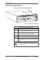
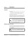
1
ATLAS 800 SERIES DUAL VIDEO MODULE
User Manual
1200773L1
61200773L1-1A
June 2002
ATLAS 800 Series Dual Video Module
Trademarks
Any brand names and product names included in this manual are trademarks, registered trademarks, or
trade names of their respective holders.
To the Holder of the Manual
The contents of this manual are current as of the date of publication. ADTRAN reserves the right to
change the contents without prior notice.
In no event will ADTRAN be liable for any special, incidental, or consequential damages or for
commercial losses even if ADTRAN has been advised thereof as a result of issue of this publication.
901 Explorer Boulevard
P.O. Box 140000
Huntsville, AL 35814-4000
Phone: (256) 963-8000
©2002 ADTRAN, Inc.
All Rights Reserved.
Printed in U.S.A.
Notes provide additional useful information.
Cautions signify information that could prevent service interruption.
Warnings provide information that could prevent damage to the equipment or
endangerment to human life.
3
Affidavit Requirements for Connection to Digital Services
•
•
•
An affidavit is required to be given to the telephone company whenever digital terminal equipment
without encoded analog content and billing protection is used to transmit digital signals containing
encoded analog content which are intended for eventual conversion into voiceband analog signals
and transmitted on the network.
The affidavit shall affirm that either no encoded analog content or billing information is being
transmitted or that the output of the device meets Part 68 encoded analog content or billing
protection specifications.
End user/customer will be responsible for filing an affidavit with the local exchange carrier when
connecting unprotected customer premise equipment (CPE) to 1.544 Mbps or subrate digital
services.
Until such time as subrate digital terminal equipment is registered for voice applications, the affidavit
requirement for subrate services is waived.
4
Affidavit for Connection of Customer Premises Equipment
to 1.544 Mbps and/or Subrate Digital Services
For the work to be performed in the certified territory of ___________________ (telco name)
State of ________________
County of ________________
I, _______________________ (name), ____________________________________ (business
address),
____________________ (telephone number) being duly sworn, state:
I have responsibility for the operation and maintenance of the terminal equipment to be
connected to 1.544 Mbps and/or ________ subrate digital services. The terminal equipment to be
connected complies with Part 68 of the FCC rules except for the encoded analog content and
billing protection specifications. With respect to encoded analog content and billing protection:
( ) I attest that all operations associated with the establishment, maintenance, and adjustment of the
digital CPE with respect to analog content and encoded billing protection information
continuously complies with Part 68 of the FCC Rules and Regulations.
( ) The digital CPE does not transmit digital signals containing encoded analog content or billing
information which is intended to be decoded within the telecommunications network.
( ) The encoded analog content and billing protection is factory set and is not under the control of the
customer.
I attest that the operator(s)/maintainer(s) of the digital CPE responsible for the establishment,
maintenance, and adjustment of the encoded analog content and billing information has (have)
been trained to perform these functions by successfully having completed one of the following
(check appropriate blocks):
( ) A. A training course provided by the manufacturer/grantee of the equipment used to encode
analog signals; or
( ) B. A training course provided by the customer or authorized representative, using training
materials and instructions provided by the manufacturer/grantee of the equipment used to
encode analog signals; or
( ) C. An independent training course (e.g., trade school or technical institution) recognized by the
manufacturer/grantee of the equipment used to encode analog signals; or
( ) D. In lieu of the preceding training requirements, the operator(s)/maintainer(s) is (are) under the
control of a supervisor trained in accordance with _________ (circle one) above.
5
I agree to provide ______________________ (telco’s name) with proper documentation to
demonstrate compliance with the information as provided in the preceding paragraph, if so
requested.
_________________________________Signature
_________________________________Title
_________________________________ Date
Transcribed and sworn to before me
This ________ day of _______________, _______
_________________________________
Notary Public
My commission expires:
_________________________________
6
Federal Communications Commission Radio Frequency Interference Statement
This equipment has been tested and found to comply with the limits for a Class A digital device,
pursuant to Part 15 of the FCC Rules. These limits are designed to provide reasonable protection
against harmful interference when the equipment is operated in a commercial environment. This
equipment generates, uses, and can radiate radio frequency energy and, if not installed and used in
accordance with the instruction manual, may cause harmful interference to radio frequencies.
Operation of this equipment in a residential area is likely to cause harmful interference in which case
the user will be required to correct the interference at his own expense.
Shielded cables must be used with this unit to ensure compliance with Class A FCC
limits.
Changes or modifications to this unit not expressly approved by the party
responsible for compliance could void the user’s authority to operate the
equipment.
Canadian Emissions Requirements
This digital apparatus does not exceed the Class A limits for radio noise emissions from digital
apparatus as set out in the interference-causing equipment standard entitled “Digital Apparatus,”
ICES-003 of the Department of Communications.
Cet appareil numérique respecte les limites de bruits radioelectriques applicables aux appareils
numériques de Class A prescrites dans la norme sur le materiel brouilleur: “Appareils Numériques,”
NMB-003 edictee par le ministre des Communications.
7
Warranty and Customer Service
ADTRAN will repair and return this product within five years from the date of shipment if it does not
meet its published specifications or fails while in service. For detailed warranty, repair, and return
information refer to the ADTRAN Equipment Warranty and Repair and Return Policy Procedure.
Return Material Authorization (RMA) is required prior to returning equipment to ADTRAN.
For service, RMA requests, or further information, contact one of the numbers listed at the end of this
section.
LIMITED PRODUCT WARRANTY
ADTRAN warrants that for five years from the date of shipment to Customer, all products
manufactured by ADTRAN will be free from defects in materials and workmanship. ADTRAN also
warrants that products will conform to the applicable specifications and drawings for such products, as
contained in the Product Manual or in ADTRAN's internal specifications and drawings for such
products (which may or may not be reflected in the Product Manual). This warranty only applies if
Customer gives ADTRAN written notice of defects during the warranty period. Upon such notice,
ADTRAN will, at its option, either repair or replace the defective item. If ADTRAN is unable, in a
reasonable time, to repair or replace any equipment to a condition as warranted, Customer is entitled to
a full refund of the purchase price upon return of the equipment to ADTRAN. This warranty applies
only to the original purchaser and is not transferable without ADTRAN's express written permission.
This warranty becomes null and void if Customer modifies or alters the equipment in any way, other
than as specifically authorized by ADTRAN.
EXCEPT FOR THE LIMITED WARRANTY DESCRIBED ABOVE, THE FOREGOING
CONSTITUTES THE SOLE AND EXCLUSIVE REMEDY OF THE CUSTOMER AND THE
EXCLUSIVE LIABILITY OF ADTRAN AND IS IN LIEU OF ANY AND ALL OTHER
WARRANTIES (EXPRESSED OR IMPLIED). ADTRAN SPECIFICALLY DISCLAIMS ALL
OTHER WARRANTIES, INCLUDING (WITHOUT LIMITATION), ALL WARRANTIES OF
MERCHANTABILITY AND FITNESS FOR A PARTICULAR PURPOSE. SOME STATES DO
NOT ALLOW THE EXCLUSION OF IMPLIED WARRANTIES, SO THIS EXCLUSION MAY
NOT APPLY TO CUSTOMER.
In no event will ADTRAN or its suppliers be liable to the Customer for any incidental, special,
punitive, exemplary or consequential damages experienced by either the Customer or a third party
(including, but not limited to, loss of data or information, loss of profits, or loss of use). ADTRAN is
not liable for damages for any cause whatsoever (whether based in contract, tort, or otherwise) in
excess of the amount paid for the item. Some states do not allow the limitation or exclusion of liability
for incidental or consequential damages, so the above limitation or exclusion may not apply to the
Customer.
8
Customer Service, Product Support Information, and Training
ADTRAN will repair and return this product if within five years from the date of shipment the product
does not meet its published specification or the product fails while in service.
A return material authorization (RMA) is required prior to returning equipment to ADTRAN. For
service, RMA requests, training, or more information, use the contact information given below.
Repair and Return
If you determine that a repair is needed, please contact our Customer and Product Service (CAPS)
department to have an RMA number issued. CAPS should also be contacted to obtain information
regarding equipment currently in house or possible fees associated with repair.
CAPS Department
(256) 963-8722
Identify the RMA number clearly on the package (below address), and return to the following address:
ADTRAN Customer and Product Service
901 Explorer Blvd. (East Tower)
Huntsville, Alabama 35806
RMA # _____________
Pre-Sales Inquiries and Applications Support
Your reseller should serve as the first point of contact for support. If additional pre-sales support is
needed, the ADTRAN Support web site provides a variety of support services such as a searchable
knowledge base, latest product documentation, application briefs, case studies, and a link to submit a
question to an Applications Engineer. All of this, and more, is available at:
http://support.adtran.com
When needed, further pre-sales assistance is available by calling our Applications Engineering
Department.
Applications Engineering (800) 615-1176
9
Post-Sale Support
Your reseller should serve as the first point of contact for support. If additional support is needed, the
ADTRAN Support web site provides a variety of support services such as a searchable knowledge
base, updated firmware releases, latest product documentation, service request ticket generation and
trouble-shooting tools. All of this, and more, is available at:
http://support.adtran.com
When needed, further post-sales assistance is available by calling our Technical Support Center.
Please have your unit serial number available when you call.
Technical Support
(888) 4ADTRAN
Installation and Maintenance Support
The ADTRAN Custom Extended Services (ACES) program offers multiple types and levels of
installation and maintenance services which allow you to choose the kind of assistance you need. This
support is available at:
http://www.adtran.com/aces
For questions, call the ACES Help Desk.
ACES Help Desk
(888) 874-ACES (2237)
Training
The Enterprise Network (EN) Technical Training Department offers training on our most popular
products. These courses include overviews on product features and functions while covering
applications of ADTRAN's product lines. ADTRAN provides a variety of training options, including
customized training and courses taught at our facilities or at your site. For more information about
training, please contact your Territory Manager or the Enterprise Training Coordinator.
10
Training Phone
(800) 615-1176, ext. 7500
Training Fax
(256) 963-6700
Training Email
[email protected]
Table of Contents
Chapter 1
Introduction .................................................................................................................................17
Video Module Overview .......................................................................................................................................17
Functional Description...........................................................................................................................................17
Features ..................................................................................................................................................................18
Video Module Specifications.................................................................................................................................18
Physical Description ..............................................................................................................................................19
Chapter 2
Installation ...................................................................................................................................21
Before Installing the Video Module ......................................................................................................................21
Shipping Contents...........................................................................................................................................21
Installing the Video Module ..................................................................................................................................22
Wiring ....................................................................................................................................................................23
Power Up and Initialization ...................................................................................................................................26
Failed Self-Test...............................................................................................................................................26
Operation Alarms............................................................................................................................................26
Chapter 3
Operation .....................................................................................................................................27
Overview................................................................................................................................................................27
Terminal Menu Structure.......................................................................................................................................27
Modules .................................................................................................................................................................28
Slt ...................................................................................................................................................................28
Type ...............................................................................................................................................................28
Menu ..............................................................................................................................................................28
Alarm .............................................................................................................................................................29
Test ................................................................................................................................................................29
State ...............................................................................................................................................................29
Status .............................................................................................................................................................29
Online .....................................................................................................................................................29
No Response ...........................................................................................................................................29
Empty .....................................................................................................................................................29
Offline .....................................................................................................................................................29
Offline/No Response ..............................................................................................................................29
Rev .................................................................................................................................................................29
Modules/Menu .......................................................................................................................................................30
Video Menus ..................................................................................................................................................30
Info .........................................................................................................................................................30
Alarm Status ...........................................................................................................................................30
DTE Status ..............................................................................................................................................31
Data Rate ................................................................................................................................................31
PLL/FIFO ...............................................................................................................................................32
Configuration ..........................................................................................................................................32
61200773L1-1A
ATLAS 800 Series Video Module User Manual
11
Table of Contents
Test ........................................................................................................................................................ 33
DTE Interface ........................................................................................................................................ 34
Current DTE Type ........................................................................................................................................ 35
Module Alarms ............................................................................................................................................. 35
Test Activity ................................................................................................................................................. 35
ATLAS Features Used with Video Module Options ............................................................................................ 35
Factory Restore ..................................................................................................................................................... 35
Run Selftest ........................................................................................................................................................... 35
Appendix A
Dial Plan Interface Configuration............................................................................................ 37
Appendix B
Smart Dial String Formats........................................................................................................ 45
Appendix C
Video Module Menu Tree ......................................................................................................... 47
Index ..................................................................................................................................................................... 49
12
ATLAS 800 Series Video Module User Manual
61200773L1-1A
List of Figures
Figure 1-1.
Figure 1-2.
Figure 2-1.
Figure 3-1.
Figure 3-2.
Figure A-1.
Figure C-1.
Video Module System......................................................................................................................17
Video Module...................................................................................................................................19
Installing the Video Module.............................................................................................................22
Modules Menu..................................................................................................................................28
Video Module Menu Options...........................................................................................................30
Dial Plan Menus ...............................................................................................................................37
ATLAS 800 Series Video Module Menu Tree ................................................................................47
61200773L1-1A
ATLAS 800 Series Video Module User Manual
13
14
ATLAS 800 Series Video Module User Manual
61200773L1-1A
List of Tables
Table 2-1.
Table 2-2.
Table 2-3.
Table 2-4.
Table 3-1.
V.35 Winchester Pinout ...................................................................................................................23
EIA-530 Connector Pinout...............................................................................................................24
RS-449 Pinout ..................................................................................................................................25
RS-366 Connector Pinout.................................................................................................................26
DTR Descriptions.............................................................................................................................33
61200773L1-1A
ATLAS 800 Series Video Module User Manual
15
16
ATLAS 800 Series Video Module User Manual
61200773L1-1A
Introduction
Chapter 1
VIDEO MODULE OVERVIEW
The Video Module is a member of the ATLAS family of integrated access products,
providing two independent video ports, each including an RS-366 dialing interface
(DB-25) and a synchronous DTE port (interface connector determined by custom
cable).
The Video Module combines with the ATLAS 800 Series base unit and other
ATLAS modules to provide a comprehensive, cost-effective solution for any organization supporting an ISDN videoconferencing network. As many Video Modules
can be installed in a system as can be physically accommodated in the ATLAS 800
Series chassis. Figure 1-1 shows a sample application.
Videoconference
Equipment
ATLAS 800 series
ISDN Network
RS-366
Video Module
T1/PRI Module
or Octal BRI Module
Nx56/64 BONDing Module Installed
DTE
Figure 1-1. Video Module System
Used in conjunction with the Nx56/64 BONDing Module, the ATLAS 800 Series
system (with an installed Video Module) will be able to terminate ISDN PRI or BRI
circuits (using the Quad T1/PRI or Octal BRI Modules, respectively) and provide
high-bandwidth video data streams to a video codec.
FUNCTIONAL DESCRIPTION
The Video Module installs in any available option slot in the ATLAS 800 Series
chassis. You can view the status of the module itself, as well as the circuits to which
it interfaces. The terminal menus are accessible using a VT100 terminal connection
(through the CONTROL port) or a Telnet session (through the Ethernet port). Use
the terminal menu to configure the Video Module and to download application software.
61200773L1-1A
ATLAS 800 Series Video Module User Manual
17
Chapter 1. Introduction
FEATURES
Features of the Video Module are listed here:
•
Two independent video ports; each includes an RS-366 dialing interface and a
DTE synchronous port
•
Adapter cables are available to provide the following DTE interfaces: V.35,
RS-449, EIA-530
•
Storage for 10 dial numbers and associated configuration parameters
•
Type II and Type III RS-366 interface support
VIDEO MODULE SPECIFICATIONS
Each DTE synchronous port of the Video Module conforms to the following specifications:
Operating Temperature
Operation: 0° C to 50° C
Storage: -20° C to 70° C
Relative Humidity: To 95% Noncondensing
Line Rate
56 kbps to 1472 kbps (in 56k or 64k steps)
Data rates greater than 64kbps require the use of the Nx56/64
BONDing module (P/N 1200262L1).
Interface Types (using custom cables)
•
V.35
Cable P/N 1200774L1
•
EIA-530
Cable P/N 1200774L2
•
RS-449
Cable P/N 1200774L3
Tests
Power-on, circuit self-test, port loopback (internal toward system), and bilateral
local loopback
Each RS-366 dialing interface of the Video Module conforms to the following specifications:
Interface Types
Type II or Type III
18
ATLAS 800 Series Video Module User Manual
61200773L1-1A
Chapter 1. Introduction
PHYSICAL DESCRIPTION
The Video Module (see Figure 1-2) plugs into any available option slot in the rear
of the ATLAS 800 Series chassis.
Figure 1-2. Video Module
The label under each 68-pin connector refers to the port on the Video Module.
61200773L1-1A
ATLAS 800 Series Video Module User Manual
19
Chapter 1. Introduction
20
ATLAS 800 Series Video Module User Manual
61200773L1-1A
Chapter 2
Installation
BEFORE INSTALLING THE VIDEO MODULE
Carefully unpack and inspect the Video Module for shipping damages. If you
suspect damage occurred during shipping, file a claim immediately with the carrier
and then contact ADTRAN Technical Support (see the front pages of this manual for
pertinent information). If possible, keep the original shipping container for returning
the Video Module for repair or for verification of shipping damage.
Shipping Contents
The ADTRAN shipment includes the following items:
•
Video Module
•
Video Module Quick Start Guide
•
Video Module User Manual (insert into the ATLAS 800 Series User Manual)
And two of the following:
61200773L1-1A
•
V.35 Cable (System P/N 4200773L1, Cable P/N 1200774L1)
•
EIA-530 Cable (System P/N 4200773L2, Cable P/N 1200774L2)
•
RS-449 Cable (System P/N 4200773L3, Cable P/N 1200774L3)
ATLAS 800 Series Video Module User Manual
21
Chapter 2. Installation
INSTALLING THE VIDEO MODULE
Figure represents the actions required to properly install the
Video Module, as described in the Step/Action table below.
Figure 2-1. Installing the Video Module
Instructions for Installing the Video Module
Step
Action
1
Remove the cover plate from the appropriate option slot in the
ATLAS 800 Series chassis rear panel.
2
Slide the Video Module into the option slot until the module is
firmly positioned against the front of the chassis.
3
Secure the thumbscrews at both edges of the module.
4
Connect the cables to the associated device(s).
5
Complete installation of remaining modules and Base Unit as
specified in the Installation chapter of the ATLAS 800 Series
User Manual.
To ensure that the thumbscrews are securely fastened, use a
screwdriver to tighten them.
22
ATLAS 800 Series Video Module User Manual
61200773L1-1A
Chapter 2. Installation
WIRING
Several DTE interface options are available, depending on the system part number
ordered. The following tables provide the pinouts for all DTE interfaces.
Connector Type
V.35 (System P/N 4200773L1)
Table 2-1. V.35 Winchester Pinout
Pin
CCITT
A
101
Protective ground (PG)
B
102
Signal ground (SG)
C
105
Request to send (RTS) from DTE
D
106
Clear to send (CTS) to DTE
E
107
Data set ready (DSR) to DTE
F
109
Received line signal detector (DCD) to DTE
H
—
Data terminal ready (DTR) from DTE
J
—
Ring indicator (RI)
R
104
Received data (RD-A) to DTE
T
104
Received data (RD-B) to DTE
V
115
RX clock (RC-A) to DTE
X
115
RX clock (RC-B) to DTE
P
103
Transmitted data (TD-A) from DTE
S
103
Transmitted data (TD-B) from DTE
Y
114
TX clock (TC-A) to DTE
AA
114
TX clock (TC-B) to DTE
U
113
External TX clock (ETC-A) from DTE
W
113
External TX clock (ETC-B) from DTE
NN
—
Test mode (TM) to DTE - (Not Supported)
61200773L1-1A
Description
ATLAS 800 Series Video Module User Manual
23
Chapter 2. Installation
Connector Type
EIA 530 (System P/N 4200773L2)
Table 2-2. EIA-530 Connector Pinout
Pin
24
Signal Description
Pin
Signal Description
1
Shield (Ground)
13
Clear to Send (B)
2
Transmit Data (A)
14
Transmit Data (B)
3
Received Data (A)
15
Transmit Clock (A)
4
Request to Send (A)
16
Received Data (B)
5
Clear to Send (A)
17
Receive Clock (A)
6
DCE Ready (A)
18
Not Used
7
Signal Ground
19
Request to Send (B)
8
Carrier Detect (A)
20
DTE Ready (A)
9
Received Clock (B)
21
Not Used
10
Carrier Detect (B)
22
DCE Ready (B)
11
Ext. Transmit Clock (B)
23
DTE Ready (B)
12
Transmit Clock (B)
24
Ext. Transmit Clock (A)
25
Not Used
ATLAS 800 Series Video Module User Manual
61200773L1-1A
Chapter 2. Installation
Connector Type
RS-449 (System P/N 4200773L3)
Table 2-3. RS-449 Pinout
Pin
Signal Description
Pin
Signal Description
1
Shield (Ground)
19
Signal Ground
2
Not Used
20
Not Used
3
Not Used
21
Not Used
4
Transmit Data (A)
22
Transmit Data (B)
5
Transmit Clock (A)
23
Transmit Clock (B)
6
Received Data (A)
24
Receive Data (B)
7
Request to Send (A)
25
Request to Send (B)
8
Receive Clock (A)
26
Receive Clock (B)
9
Clear to Send (A)
27
Clear to Send (B)
10
Local Loopback - (Not Supported)
28
Not Used
11
DCE Ready (A)
29
DCE Ready (B)
12
DTE Ready (A)
30
DTE Ready (B)
13
Carrier Detect (A)
31
Carrier Detect (B)
14
Remote Loopback - (Not Supported)
32
Not Used
15
Ring Indicator
33
Not Used
16
Not Used
34
Not Used
17
Ext. Transmit Clock (A)
35
Ext. Transmit Clock (B)
18
Test Mode - (Not Supported)
36
Not Used
37
Not Used
61200773L1-1A
ATLAS 800 Series Video Module User Manual
25
Chapter 2. Installation
Connector Type
RS-366 (DB-25)
Table 2-4. RS-366 Connector Pinout
Pin
Signal Description
Pin
Signal Description
1
Shield (Ground)
14
Digit Signal Circuit 1 (NB1)
2
Digit Present (DPR)
15
Digit Signal Circuit 2 (NB2)
3
Abandon Call and Retry (ACR)
16
Digit Signal Circuit 4(NB4)
4
Call Request (CRQ)
17
Digit Signal Circuit 8(NB8)
5
Present Next Digit (PND)
18
Receive Common (RC)
6
Power Indication (PWI)
19
Send Common (SC)
7
Signal Ground (SG)
8-12
13
Not Used
20-21
22
Distant Station Connection (DSC)
23-25
Not Used
Data Link Occupied (DLO)
Not Used
POWER UP AND INITIALIZATION
The Video Module requires no initialization input during the power-up sequence, as
described in the ATLAS 800 Series User Manuals. Any previously configured setting for the Video Module is automatically restored upon power-up.
Failed Self-Test
If the Video Module fails self-test, a message will be displayed in the terminal menu
self-test log during power-up. See the appropriate ATLAS 800 Series User Manual
for details.
Operation Alarms
The red ALARM LED (located with the Module LEDs on the front panel) illuminates when an alarm condition is detected.
26
ATLAS 800 Series Video Module User Manual
61200773L1-1A
Chapter 3
Operation
OVERVIEW
You can control and configure the Video Module from a variety of sources, including the following:
•
The terminal menus, allowing detailed configuration, status, and diagnostics
•
SNMP, primarily for reporting alarm conditions and system status
The remainder of this section describes the menu items presented when managing
the Video Module via the terminal menu.
Access the terminal menu using either a VT-100 terminal attached to the ATLAS
800 Series Base Unit’s control port or a Telnet session established through the Base
Unit’s Ethernet port. The appropriate ATLAS 800 Series User Manual provides detailed instructions on the operation of each of these management approaches.
To edit items in the terminal menu, you must have the appropriate
password level. Each menu description in this section indicates the
password level required for write and read access. See “Access
Passwords” in the appropriate ATLAS 800 Series User Manual
for detailed information on working with passwords. Security level
0 users can view and edit every available field. Security level 5
users can view any field but cannot edit.
TERMINAL MENU STRUCTURE
ATLAS 800 Series uses a hierarchical menu structure to provide access to all of its
features. The top-most menu level leads to submenus which are grouped by functionality. All menu items display in the terminal window. To access the Video Module, activate the MODULES menu. The following sections describe the menu items
for the MODULES menu.
Refer to the appropriate ATLAS 800 Series User Manual for
detailed instructions on navigating through the terminal menu.
61200773L1-1A
ATLAS 800 Series Video Module User Manual
27
Chapter 3. Operation
MODULES
The ATLAS 800 Series system controller automatically detects the presence of the
Video Module when it is installed in the system. To see the menus for the Video
Module via the terminal menu, use the arrow keys to scroll to the Modules menu and
press Enter to access the module choices. Figure 3-1 shows the Modules menu (see
also the menu tree in Appendix C). The following sections describe all the Modules’
menu options.
Figure 3-1. Modules Menu
SLT
Read security: 5
Displays the number of the available slots in the ATLAS 800 Series chassis. Slot 0
refers to the ATLAS 800 Series unit. This field is read-only.
TYPE
Write security: 3; Read security: 5
Displays the type of module actually installed in the slot or the type of module you
plan to install in the slot. If a Video Module is installed, the Type field automatically defaults to VIDEO (the Video Module). You can use this field to preconfigure
a system before actually installing modules by simply specifying the module that
you want to install in each slot.
TYPE automatically displays the name of an installed module. If
you want to change this field to a different type of module, you
must set TYPE to EMPTY before selecting the other module.
MENU
28
Displays additional status and configuration menus for the selected module. (To access the submenus for this item, use the arrow keys to scroll to the MENU column for
the module you want to edit, and press Enter.) For detailed information on each submenu item, see the section See “Modules/Menu” on page 30.
ATLAS 800 Series Video Module User Manual
61200773L1-1A
Chapter 3. Operation
ALARM
Read security: 5
Displays an alarm condition on the Video Module. Press Enter in this field to activate the menu.
TEST
Read security: 5
Displays test name if the Video Module is executing a test. Press Enter in this field
to activate the menu.
STATE
Displays module status as either ONLINE or OFFLINE. Even though a module is
physically installed, it must be marked as online for it to be considered an available
resource. This field allows an installed module to be marked as offline, which may
be useful in system troubleshooting. If you choose OFFLINE, the module will not be
in alarm condition but will display OFFLINE.
Once a module is installed, STATE must be set to ONLINE for the
ATLAS 800 Series unit to use the module for any data bandwidth.
STATUS
This read-only field provides status information on the Video Module. The following messages may display:
ONLINE
The module is enabled, and is responding to the system controller’s status polls.
This is the normal response of the system.
NO RESPONSE
The module is enabled, but is not responding to the system controller’s status polls.
This response indicates either a problem in the system or that the module is not installed.
EMPTY
The system controller has not detected the presence of a module in the slot, nor has
a module been manually enabled for this option slot.
OFFLINE
The module is installed, but has been taken offline by a user. The module is still responding to controller polls.
OFFLINE/NO
RESPONSE
The module is installed, but has been taken offline by a user. The module is not responding to polls.
REV
61200773L1-1A
This read-only field displays the hardware revision of the Video Module.
ATLAS 800 Series Video Module User Manual
29
Chapter 3. Operation
MODULES/MENU
Figure 3-2 shows the menu options available for the Video Module (see also the
menu tree in Appendix C). The following sections describe these options.
Figure 3-2. Video Module Menu Options
VIDEO MENUS
INFO
Accesses additional submenus.
Provides information about module part number, serial number , and board revision.
PART NUMBER
Displays the part number of the module (read only).
SERIAL NUMBER
Displays the serial number of the module (read only).
BOARD REVISION
Displays the PCB revision (read only).
ALARM STATUS
Displays the current alarm state of the DTE interface including the following:
SLIP
A rate mismatch exists between the DTE clock and the network-side clock (as set
by DS0 assignment).
PLL
The Video Module DTE port is not able to lock onto the clock provided by the network interface.
30
ATLAS 800 Series Video Module User Manual
61200773L1-1A
Chapter 3. Operation
ZERO
The DTE is sending an excessive number of consecutive zeroes to the network
interface.
NO EXT CLK
The DTE is not providing an external transmit clock. This alarm displays only if the
Video Module DTE port is configured to get its transmit clock from the DTE.
DTE STATUS
Shows the status of key DTE interface signals. An asterisk (*) indicates the presence of a signal and a hyphen (-) indicates no signal present.
PRT
Operating port number
The following signals are monitored (these options are read-only):
DATA RATE
61200773L1-1A
RTS
Request to send from DTE
CTS
Clear to send to DTE
DTR
Data terminal ready from DTE
DSR
Data set ready to DTE
DCD
Data carrier detect to DTE
RI
Ring indicate to DTE
TD
Transmit data from the DTE
RD
Receive data toward the DTE
EC
External clock present
Displays the data rate at which each Video Module DTE port is currently operating.
A port’s data rate is determined by the number of B channels assigned to it and the
rate per channel associated with the active call.
ATLAS 800 Series Video Module User Manual
31
Chapter 3. Operation
PLL/FIFO
CONFIGURATION
Displays the Phase Lock Loop (PLL) and FIFO status.
PORT
Indicates the operating port.
PLL/FIFO
Displays the state of the PLL and FIFO systems.
LOCK
PLL is locked (This is required to transfer data.)
RXE
Receive data FIFO empty
RXF
Receive data FIFO full
TXE
Transmit data FIFO empty
TXF
Transmit data FIFO full
All of the following configurable parameters apply to the individual Video Module
DTE ports.
PRT
Displays the port number.
PORT NAME
Accepts any alpha-numeric name up to 16 characters long, to uniquely identify
each DTE port on the Video Module.
CLK +/Controls the clock used by the ATLAS 800 Series to accept the transmit (TX) data
from the DTE. This is usually set to NORMAL. If the interface cable is long, causing
a phase shift in the data, the clock can be set to INVERTED. This switches the phase
of the clock, which compensates for a long cable.
DATA
Controls the inverting of the DTE data. This inversion can be useful when operating with a high-level data link control (HDLC) protocol (often used as a means to
ensure 1s density). Select either NORMAL or INVERTED. Data inversion configuration must match on both ends of the circuit.
CTS
Determines the behavior of the Clear To Send (CTS) signal. If set to NORMAL, CTS
will follow the value of Request To Send (RTS). If set to FORCED ON, CTS will
always be asserted.
DCD
Determines the behavior of the Data Carrier Detect (DCD) signal, also called
RLSD on some interfaces. If set to NORMAL, DCD will generally be asserted when
the interface is capable of passing data (consult the appropriate ATLAS 800 Series
User Manual for exact conditions.) If set to FORCED ON, DCD will always be
asserted.
DSR
Determines the behavior of the Data Set Ready (DSR) signal. If set to NORMAl,
DSR will generally be asserted when the interface is capable of passing data. If set
to FORCED ON, DSR will always be asserted.
32
ATLAS 800 Series Video Module User Manual
61200773L1-1A
Chapter 3. Operation
DTR
Selects the response to DTR transitions. The following table lists the configuration
options for the DTR parameter with respect to the current configuration for the
module in the Dial Plan.
Table 3-1. DTR Descriptions
Dial Method (Dial Plan)
DIAL ON DTR
RS-366
MANUAL
DTR
Setting
Description
Recognize
DTR
Call is dialed when DTR is high and disconnects when DTR goes low.
Ignore DTR
Call will never connect.
Recognize
DTR
Call is dialed if DTR is already high and
disconnected when DTR goes low.
Ignore DTR
Call is dialed regardless of DTR state and
must be disconnected manually.
Recognize
DTR
Call is dialed if DTR is already high and
disconnected when DTR goes low.
Ignore DTR
Call is dialed regardless of DTR state and
must be disconnected manually.
0 INH
When the port detects an uninterrupted string of 0s being transmitted for more than
one second, setting this parameter to ON will cause the ATLAS 800 Series to send
1s toward the network.
TEST
These options initiate different types of tests and display test results.
LOOPBACK
The Dual Video Module supports both local and remote loopbacks. Selecting
LOCAL LOOPBACK or REMOTE LOOPBACK initiates the appropriate loopback
sequence.
NO LOOPBACK
No active loopback
LOCAL LOOPBACK
Activates both a local loopback (back toward the DTE) and a port loopback
(toward the network)
REMOTE LOOPBACK
Initiates a local loopback request sent to the remote Dual Video Module. This
allows for end-to-end circuit test.
The REMOTE LOOPBACK option is only supported for Dual Video
Module to Dual Video Module applications.
61200773L1-1A
ATLAS 800 Series Video Module User Manual
33
Chapter 3. Operation
LOOPBACK STATUS
This read-only option indicates a port’s current loopback status by displaying any
of the following status messages:
NO LOOPBACK ACTIVE
PORT LOOPBACK ACTIVE
LOOPING UP REMOTE UNIT...
REMOTE UNIT LOOPED BACK
LOOPING DOWN REMOTE UNIT...
REMOTE LOOPUP FAILED
PORT LOOPED FROM REMOTE SOURCE
511
Controls the activation of the 511 test pattern generator and detector. 511 pattern is
generated inward through the ATLAS System.
511 RESULT
Displays the results of the 511 test. This option is read-only. Clear these results by
pressing Enter when CLR is selected.
NONE
Pattern is not synchronized
LOS
At one point the pattern was synchronized, but is currently not synchronized
SYNC
Pattern is synchronized
ES
Number of seconds with at least one bit error
CLR
Clears error counters on test pattern results menu.
INJ
Injects errors into transmitted test pattern.
DTE INTERFACE
Configures the DTE port of the Video Module for the appropriate interface type. Select the parameters matching the interface cable being used.
PRT
Displays the port number.
DTE INTERFACE
Configures the DTE port interface type. The following options are available:
AUTO
The ATLAS 800 Series will automatically detect the interface type. The cable
must be connected before the interface can be determined.
EIA-530
Configures the interface for EIA-530 use.
34
ATLAS 800 Series Video Module User Manual
61200773L1-1A
Chapter 3. Operation
V.35
Configures the interface for V.35 use.
RS-449
Configures the interface for RS-449 use.
LOOPBACK
Configures the interface to emulate a connected loopback cable.
CURRENT DTE TYPE Displays the current configuration of the Video Module DTE Interface.
MODULE ALARMS
Provides a shortcut to the ALARM menu (see See “Alarm Status” on page 30.).
TEST ACTIVITY
Provides a shortcut to the TEST menu (see See “Test” on page 33.)
ATLAS FEATURES USED WITH VIDEO MODULE OPTIONS
Two additional ATLAS 800 Series menu items can operate in conjunction with the
Video Module: FACTORY RESTORE and RUN SELFTEST.
FACTORY
RESTORE
You can restore the factory default settings for an Video Module by pressing F either while the cursor is over the SLT number (this action restores the factory settings
for all of the module options) or while the cursor is over an individual field (this action restores factory settings only for the particular field).
RUN SELFTEST
RUN SELFTEST, a submenu of the ATLAS 800 Series main menu item TEST, executes both the Video Module internal test and the ATLAS 800 Series internal test.
For additional information on RUN SELFTEST, see the ATLAS 800 Series User Manual.
When RUN SELFTEST displays, place the cursor on it and press Enter to execute
the test. The unit continuously changes the display on the self-test log screen until
all test results are shown.
61200773L1-1A
ATLAS 800 Series Video Module User Manual
35
Chapter 3. Operation
36
ATLAS 800 Series Video Module User Manual
61200773L1-1A
Appendix A
Dial Plan Interface Configuration
The IFCE CONFIG option for the DIAL PLAN menu (see Figure A-1) sets configuration parameters for the endpoint. These parameters vary by the type of port selected.
The following section describes the configuration options available for the ATLAS
800 Series Video Module. To access these options, select DIAL PLAN from the
ATLAS menu.
The Video Module is only available for User Term applications
Figure A-1. Dial Plan Menus
61200773L1-1A
ATLAS 800 Series Video Module User Manual
37
Appendix A. Dial Plan Interface Configuration
ATLAS 800 SERIES VIDEO MODULE: USER TERMINATION
The ATLAS 800 Series Video Module acts like the network while interfacing to user
equipment (video equipment). When you are working in the USER TERM section of
the DIAL PLAN menu and SLT is defined as a Video Module, the following interface
configuration options are available:
DIALING METHOD
Write Security: 3; Read Security: 5
Selects the method of dialing outbound calls from this endpoint.
RS-366
Configures the RS-366 dialing interface (associated with this port) to initiate the
call.
MANUAL
All outbound calls on this interface must be manually initiated and disconnected using the dial plan menus.
ON DTR
An outbound call to the number entered in the DIAL NUMBER field will be initiated
when the Data Transmit Ready (DTR) signal goes high (or active). Calls will be disconnected upon a loss of DTR.
The following menus are available only when the DIALING METHOD is RS-366.
RS-366 TYPE
TYPE II
RS-366 is used to select and dial a number entered in the STORED NUMBERS table.
TYPE III
RS-366 is used to specify the number to dial and the call parameters using the ADTRAN Smart Dial String format (see Appendix B, Smart Dial String Formats, for
more details.)
DIAL AFTER
38
Write Security: 3; Read Security: 5
Specifies the interface type for the RS-366 dialing port.
Write Security: 3; Read Security: 5
Some RS-366-capable devices will terminate a dial string with an End-Of-Number
(EON) character. If the device does not transmit such a character, the ATLAS will
use this value to assume the number is complete and proceed. The following
options are available:
1 SEC OR EON
10 SEC OR EON
2 SEC OR EON
20 SEC OR EON
5 SEC OR EON
WAIT FOR EON
ATLAS 800 Series Video Module User Manual
61200773L1-1A
Appendix A. Dial Plan Interface Configuration
STORED
NUMBERS
Write Security: 3; Read Security: 5
Enter the numbers to dial using the RS-366 Type II dialing interface in the stored
numbers list. This list can contain up to 10 stored numbers.
#
Entry number (1-10)
DIAL
Activator to dial or disconnect a call to the specified number.
DESCRIPTION Alphanumeric character string (up to 20 characters) used as a descriptor for the number entry. Enter a useful description such as VCon5thFloor(Corp).
DIGITS
Number string (up to 22 digits) to dial.
TYPE
Specifies whether the data rate on the call will be 56 or 64 kbps.
DIAL AS
Specifies the call type used to populate the Bearer Capability Information Element
in the ISDN Call Setup Message. Options include: DIGITAL (Data), VOICE (speech),
or AUDIO (3.1 kHz audio).
SRC ID
Defines the source ID assigned to this call to be used for internal ATLAS routing.
Source IDs simplify the creation of a dial plan in applications where the criterion for
switching calls to a certain endpoint is a function of which endpoint originated the
call.
Zero (0) is the default ID for all endpoints and all accept numbers. If all default
SOURCE ID values are not modified, calls are routed based only on the dialed number.
Multiple endpoints may have the same SOURCE ID. When creating the CALL
ACCEPT list, specify a SOURCE ID (s) as well as a dialed number or range of dialed
numbers to accept on that endpoint.
MIN DS0S
This option will specify the minimum number of DS0s necessary for this switched
call. If the call is negotiated and the minimum DS0s value is not met, the call will
be disconnected. Any value other than 1 requires a BONDING resource to inverse
multiplex the multiple switched channels together.
MAX DS0S
This option will specify the maximum number of DS0s allowed for this switched
call. If the call is negotiated and the maximum DS0s value is not acceptable to the
answering equipment, the call will be disconnected. Any value other than 1 requires
a BONDING resource to inverse multiplex the multiple switched channels together.
DEFAULT CALL
TYPE
61200773L1-1A
Write Security: 3; Read Security: 5
Specifies the data rate for single call as either 56 or 64 kbps if not specified in the
Smart Dial string.
ATLAS 800 Series Video Module User Manual
39
Appendix A. Dial Plan Interface Configuration
DEFAULT DIAL
CALL AS
Write Security: 3; Read Security: 5
Specifies the call type used to populate the Bearer Capability Information Element
in the ISDN Call Setup Message if not specified in the Smart Dial string. Options
include: DIGITAL (Data), VOICE (Speech), or AUDIO (3.1kHz audio).
DEFAULT
SOURCE ID
Write Security: 3; Read Security: 5
Defines the source ID assigned to this call to be used for internal ATLAS routing
when not otherwise specified in the Smart Dial string. Refer to Src ID discussion
on page 39 for more details.
DEFAULT MIN
DS0S
Write Security: 3; Read Security: 5
This option will specify the minimum number of DS0s necessary for this switched
call if not otherwise specified in the Smart Dial string. If the call is negotiated and
the minimum DS0s value is not met, the call will be disconnected. Any value other
than 1 requires a BONDING resource to inverse multiplex the multiple switched
channels together.
DEFAULT MAX
DS0S
Write Security: 3; Read Security: 5
This option will specify the maximum number of DS0s allowed for this switched
call if not otherwise specified in the Smart Dial string. If the call is negotiated and
the maximum DS0s value is not acceptable to the answering equipment, the call
will be disconnected. Any value other than 1 requires a BONDING resource to
inverse multiplex the multiple switched channels together.
MIN INCOMING
DS0S
Write Security: 3; Read Security: 5
This option will specify the minimum number of DS0s necessary for an incoming
switched call to this endpoint. If the call is negotiated and the minimum DS0s value
is not met, the call will be disconnected. Any value other than 1 requires a
BONDING resource to inverse multiplex the multiple switched channels together.
MAX INCOMING
DS0S
Write Security: 3; Read Security: 5
This option will specify the maximum number of DS0s allowed for an incoming
switched call to this endpoint. If the call is negotiated and the maximum DS0s
value is not acceptable to the answering equipment, the call will be disconnected.
Any value other than 1 requires a BONDING resource to inverse multiplex the
multiple switched channels together.
40
ATLAS 800 Series Video Module User Manual
61200773L1-1A
Appendix A. Dial Plan Interface Configuration
The following menus are only available when the DIALING METHOD is MANUAL.
REDIAL NUMBER
Write Security: 3; Read Security: 5
Activator to dial or disconnect a call to the specified number.
DIAL NUMBER
Write Security: 3; Read Security: 5
Specifies the number to dial on an outgoing call.
CALL TYPE
Write Security: 3; Read Security: 5
Specifies whether the data rate on the call will be 56 or 64kbps.
DIAL CALL AS
Write Security: 3; Read Security: 5
Specifies the call type used to populate the Bearer Capability Information Element
in the ISDN Call Setup Message. Options include: DIGITAL (Data), VOICE (speech),
or AUDIO (3.1 kHz audio).
SOURCE ID
Write Security: 3; Read Security: 5
Defines the source ID assigned to this call to be used for internal ATLAS routing.
Source IDs simplify the creation of a dial plan in applications where the criterion
for switching calls to a certain endpoint is a function of which endpoint originated
the call.
MIN DS0S
Write Security: 3; Read Security: 5
This option will specify the minimum number of DS0s necessary for this switched
call. If the call is negotiated and the minimum DS0s value is not met, the call will
be disconnected. Any value other than 1 requires a BONDING resource to inverse
multiplex the multiple switched channels together.
MAX DS0S
Write Security: 3; Read Security: 5
This option will specify the maximum number of DS0s allowed for this switched
call. If the call is negotiated and the maximum DS0s value is not acceptable to the
answering equipment, the call will be disconnected. Any value other than 1 requires
a BONDING resource to inverse multiplex the multiple switched channels
together.
STORED
NUMBERS
Write Security: 3; Read Security: 5
Enter the numbers to dial using the RS-366 Type II dialing interface in the stored
numbers list. This list can contain up to 10 stored numbers.
#
61200773L1-1A
Entry number (1-10).
ATLAS 800 Series Video Module User Manual
41
Appendix A. Dial Plan Interface Configuration
DIAL
Activator to dial or disconnect a call to the specified number.
DESCRIPTION Alphanumeric character string (up to 20 characters) used as a descriptor for the number entry. Enter a useful description such as VCon5thFloor(Corp).
DIGITS
Number string (up to 10 digits) to dial.
TYPE
Specifies whether the data rate on the call will be 56 or 64kbps.
DIAL AS
Specifies the call type used to populate the Bearer Capability Information Element
in the ISDN Call Setup Message. Options include: Digital (Data), Voice (speech),
or Audio (3.1kHz audio).
SRC ID
Defines the source ID assigned to this call to be used for internal ATLAS routing.
Source IDs simplify the creation of a dial plan in applications where the criterion for
switching calls to a certain endpoint is a function of which endpoint originated the
call.
Zero (0) is the default ID for all endpoints and all accept numbers. If all default
SOURCE ID values are not modified, calls are routed based only on the dialed
number.
Multiple endpoints may have the same SOURCE ID. When creating the CALL ACCEPT list, specify a SOURCE ID(s) as well as a dialed number or range of dialed
numbers to accept on that endpoint.
MIN DS0S
This option will specify the minimum number of DS0s necessary for this switched
call. If the call is negotiated and the minimum DS0s value is not met, the call will
be disconnected. Any value other than 1 requires a BONDING resource to inverse
multiplex the multiple switched channels together.
MAX DS0S
This option will specify the maximum number of DS0s allowed for this switched
call. If the call is negotiated and the maximum DS0s value is not acceptable to the
answering equipment, the call will be disconnected. Any value other than 1 requires
a BONDING resource to inverse multiplex the multiple switched channels together.
MIN INCOMING
DS0S
Write Security: 3; Read Security: 5
This option will specify the minimum number of DS0s necessary for an incoming
switched call to this endpoint. If the call is negotiated and the minimum DS0s
value is not met, the call will be disconnected. Any value other than 1 requires a
BONDING resource to inverse multiplex the multiple switched channels together.
MAX INCOMING
DS0S
Write Security: 3; Read Security: 5
This option will specify the maximum number of DS0s allowed for an incoming
switched call to this endpoint. If the call is negotiated and the maximum DS0s
value is not acceptable to the answering equipment, the call will be disconnected.
Any value other than 1 requires a BONDING resource to inverse multiplex the
multiple switched channels together.
42
ATLAS 800 Series Video Module User Manual
61200773L1-1A
Appendix A. Dial Plan Interface Configuration
The following menus are only available when the DIALING METHOD is ON DTR.
DIAL NUMBER
Write Security: 3; Read Security: 5
Specifies the number to dial on an outgoing call.
CALL TYPE
Write Security: 3; Read Security: 5
Specifies whether the data rate on the call will be 56 or 64kbps.
DIAL CALL AS
Write Security: 3; Read Security: 5
Specifies the call type used to populate the Bearer Capability Information Element
in the ISDN Call Setup Message. Options include: DIGITAL (Data), VOICE (speech),
or AUDIO (3.1kHz audio).
SOURCE ID
Write Security: 3; Read Security: 5
Defines the source ID assigned to this call to be used for internal ATLAS routing.
Source IDs simplify the creation of a dial plan in applications where the criterion
for switching calls to a certain endpoint is a function of which endpoint originated
the call.
MIN DS0S
Write Security: 3; Read Security: 5
This option will specify the minimum number of DS0s necessary for this switched
call. If the call is negotiated and the minimum DS0s value is not met, the call will
be disconnected. Any value other than 1 requires a BONDING resource to inverse
multiplex the multiple switched channels together.
MAX DS0S
Write Security: 3; Read Security: 5
This option will specify the maximum number of DS0s allowed for this switched
call. If the call is negotiated and the maximum DS0s value is not acceptable to the
answering equipment, the call will be disconnected. Any value other than 1 requires
a BONDING resource to inverse multiplex the multiple switched channels
together.
MIN INCOMING
DS0S
Write Security: 3; Read Security: 5
This option will specify the minimum number of DS0s necessary for an incoming
switched call to this endpoint. If the call is negotiated and the minimum DS0s
value is not met, the call will be disconnected. Any value other than 1 requires a
BONDING resource to inverse multiplex the multiple switched channels together.
61200773L1-1A
ATLAS 800 Series Video Module User Manual
43
Appendix A. Dial Plan Interface Configuration
MAX INCOMING
DS0S
44
Write Security: 3; Read Security: 5
This option will specify the maximum number of DS0s allowed for an incoming
switched call to this endpoint. If the call is negotiated and the maximum DS0s
value is not acceptable to the answering equipment, the call will be disconnected.
Any value other than 1 requires a BONDING resource to inverse multiplex the
multiple switched channels together.
ATLAS 800 Series Video Module User Manual
61200773L1-1A
Appendix B
Smart Dial String Formats
The Video Module accepts changes to Call Type and Channel Rate by using suffix
commands appended to the end of the dial string. The following string format is
used.
Where #C changes the Call Type as follows:
3=56K Data
4=64K Data
Where #R changes the Channel Rate (number of ISDN B channels) as follows:
1=1 B Channel (1x56k, 1x64k)
2=2 B Channel (2x56k, 2x64k) BONDING Mode 1
3=3 B Channel (3x56k, 3x64k) BONDING Mode 1
.
.
.
23=23 B Channel (23x56k, 23x64k) BONDING Mode 1
Where #S changes the Source ID (valid range 0-9) to route the call through the Dial
Plan.
The following are dialing examples:
61200773L1-1A
BONDING 384k using 64K call type (6x64k)
7082906055#4#6#0
BONDING 336k using 56K call type (6x56k)
7082906055#3#6#0
BONDING 256k using 64K call type (4x64k)
7082906055#4#4#0
BONDING 256k using 64k call type (4x64k)
with Source ID 5
7082906055#4#4#5
ATLAS 800 Series Video Module User Manual
45
Appendix B. Smart Dial String Formats
If no suffix is used, the call is placed using the values configured for the Video
Module. For example, if the Dual Video Module is configured with DEFAULT CALL
TYPE = 64k digital data, SOURCE ID = 0, DEFAULT MIN DS0S = (2, 3, 4, 5, or 6),
and DEFAULT MAX DS0S = 6, the dial string 7082906055 is the same as
7082906055#4#6#0.
If the Channel Rate suffix is used, the Call Type suffix is required. However, the
Channel Rate is not required to make changes to the Call Type. For example, if the
Video Module defaults configure the port for 384k Call Type, only the #3 suffix is
required to change the Call Type to 336k. The dial string 7082906055#3 is the same
as 7082906055#3#6.
If the Source ID suffix (#S) is used, both the Call Type (#C) and the Channel Rate
(#R) Suffixes are required. However, the Source ID suffix (#S) is not required to
make changes to the Call Type or Channel Rate. For example, if the Video Module
defaults configure the port for 384k (6x64k) on Source ID=0, only the #3 and #8 suffixes are required to change the call type to 448k. The dial string 7082906055#3#8
is the same as 7082906055#3#8#0.
46
ATLAS 800 Series Video Module User Manual
61200773L1-1A
Appendix C
Video Module Menu Tree
Info
Part Number
Serial Number
Board Revision
Slt
Video Menu
Type
Modules Menu
Module Alarms
SLIP
Alarm Status
Port
(shortcut)
Alarms
Alarm
PLL
Zero
No Ext Clk
Test
DTE Status
Port
State
DTE Status
Rev
Data Rate
Port
Rate
RTS
CTS
Port
DTR
Name
DSR
Clk + / -
DCD
Normal
Inverted
RI
Data
Normal
TD
PLL Fifo
Port
Inverted
RD
LOCK
EC
RXE
PLL/Fifo
RXF
CTS
Normal
Forced On
DCD
Normal
TXE
TXF
Forced On
DSR
Configuration
Normal
Forced On
DTR
Ignore DTR
Recognize DTR
Test Activity
Port
No Loopback
Test
Loopback
Local Loopback
(shortcut)
Loopback Status
0 Inh
Off
On
511
ON
OFF
511 Results
Clr
Inject
Y
ES
N
EIA
Prt
DTE Interface
Sync
DTE Interface Mode
AUTO
EIA-530
V.35
Current DTE Type
RS-449
Loopback
Figure C-1. ATLAS 800 Series Video Module Menu Tree
61200773L1-1A
ATLAS 800 Series Video Module User Manual
47
Appendix C. Video Module Menu Tree
48
ATLAS 800 Series Video Module User Manual
61200773L1-1A
Index
A
alarms . . . . . . . . . . . . . . . . . . . . . . . . . . . . . . . . . . . 26
ATLAS menus
FACTORY RESTORE . . . . . . . . . . . . . . . . . . . . . 35
RUN SELFTEST . . . . . . . . . . . . . . . . . . . . . . . . 35
D
Data Rate . . . . . . . . . . . . . . . . . . . . . . . . . . . . . . . .
Dial
Smart String . . . . . . . . . . . . . . . . . . . . . . . . . .
DIAL PLAN . . . . . . . . . . . . . . . . . . . . . . . . . . . . . . .
Dialing Method . . . . . . . . . . . . . . . . . . . . . . . . . . .
DTE Interface . . . . . . . . . . . . . . . . . . . . . . . . . . . .
31
45
37
38
34
E
EIA-530 connector pinout . . . . . . . . . . . . . . . . . . . 24
F
features . . . . . . . . . . . . . . . . . . . . . . . . . . . . . . . . . . 18
I
initialization . . . . . . . . . . . . . . . . . . . . . . . . . . . . . . 26
installing the module . . . . . . . . . . . . . . . . . . . . . . . 22
preliminary steps . . . . . . . . . . . . . . . . . . . . . . 21
M
Menu
Call Type . . . . . . . . . . . . . . . . . . . . . . . . . 41,
Default Call Type . . . . . . . . . . . . . . . . . . . . . .
Default Dial Call As . . . . . . . . . . . . . . . . . . . .
Default Max DS0s . . . . . . . . . . . . . . . . . . . . .
Default Min DS0s . . . . . . . . . . . . . . . . . . . . . .
Default Source ID . . . . . . . . . . . . . . . . . . . . . .
Dial After . . . . . . . . . . . . . . . . . . . . . . . . . . . .
Dial Call As . . . . . . . . . . . . . . . . . . . . . . . 41,
Dial Number . . . . . . . . . . . . . . . . . . . . . . . 41,
Max DS0s . . . . . . . . . . . . . . . . . . . . . . . . . 41,
Max Incoming DS0s . . . . . . . . . . . . . . 40, 42,
Min DS0s . . . . . . . . . . . . . . . . . . . . . . . . . 41,
Min Incoming DS0s . . . . . . . . . . . . . . 40, 42,
Redial Number . . . . . . . . . . . . . . . . . . . . . . . .
61200773L1-1A
43
39
40
40
40
40
38
43
43
43
44
43
43
41
Source ID . . . . . . . . . . . . . . . . . . . . . . . . . 41, 43
Stored Numbers . . . . . . . . . . . . . . . . . . . . 39, 41
Menu Tree . . . . . . . . . . . . . . . . . . . . . . . . . . . . . . . 47
MODULES menus and submenus . . . . . . . . . . . . . . 28
ALARMS . . . . . . . . . . . . . . . . . . . . . . . . . . . . . . 29
MENU . . . . . . . . . . . . . . . . . . . . . . . . . . . . . . . 28
See also, MODULES/MENU.
REV . . . . . . . . . . . . . . . . . . . . . . . . . . . . . . . . . 29
SLT . . . . . . . . . . . . . . . . . . . . . . . . . . . . . . . . . 28
STATE . . . . . . . . . . . . . . . . . . . . . . . . . . . . . . . 29
STATUS . . . . . . . . . . . . . . . . . . . . . . . . . . . . . . 29
TEST . . . . . . . . . . . . . . . . . . . . . . . . . . . . . . . . . 29
TYPE . . . . . . . . . . . . . . . . . . . . . . . . . . . . . . . . 28
MODULES/MENU . . . . . . . . . . . . . . . . . . . . . . . . . . 30
ALARM STATUS . . . . . . . . . . . . . . . . . . . . . . . . 30
BOARD REVISION . . . . . . . . . . . . . . . . . . . . . . 30
CONFIGURATION . . . . . . . . . . . . . . . . . . . . . . . 32
DTE STATUS . . . . . . . . . . . . . . . . . . . . . . . . . . 31
INFO . . . . . . . . . . . . . . . . . . . . . . . . . . . . . . . . . 30
MODULE ALARMS . . . . . . . . . . . . . . . . . . . . . . 35
PART NUMBER . . . . . . . . . . . . . . . . . . . . . . . . . 30
SERIAL NUMBER . . . . . . . . . . . . . . . . . . . . . . . 30
TEST ACTIVITY . . . . . . . . . . . . . . . . . . . . . . . . 35
O
operation overview . . . . . . . . . . . . . . . . . . . . . . . . . 27
P
pinout
network connection . . . . . . . . . . . . . . . . . . . . . 23
RS-366 Interface . . . . . . . . . . . . . . . . . . . . . . . 26
PLL/FIFO . . . . . . . . . . . . . . . . . . . . . . . . . . . . . . . . 32
power up . . . . . . . . . . . . . . . . . . . . . . . . . . . . . . . . . 26
R
RS-366 Pinout . . . . . . . . . . . . . . . . . . . . . . . . . . . . 26
RS-366 Type . . . . . . . . . . . . . . . . . . . . . . . . . . . . . 38
RS-449 pinout . . . . . . . . . . . . . . . . . . . . . . . . . . . . 25
ATLAS 800 Series Video Module User Manual
49
Index
S
self test, failed . . . . . . . . . . . . . . . . . . . . . . . . . . . . .26
self-test failure . . . . . . . . . . . . . . . . . . . . . . . . . . . .26
shipping contents . . . . . . . . . . . . . . . . . . . . . . . . . .21
Smart Dial
Call Type . . . . . . . . . . . . . . . . . . . . . . . . . . . . .45
Channel rate . . . . . . . . . . . . . . . . . . . . . . . . . . .45
Source ID . . . . . . . . . . . . . . . . . . . . . . . . . . . . .45
specifications . . . . . . . . . . . . . . . . . . . . . . . . . . . . .18
interface types . . . . . . . . . . . . . . . . . . . . . . . . .18
line rate . . . . . . . . . . . . . . . . . . . . . . . . . . . . . .18
RS-366 dialing interface . . . . . . . . . . . . . . . . .18
tests . . . . . . . . . . . . . . . . . . . . . . . . . . . . . . . . .18
T
terminal menu structure . . . . . . . . . . . . . . . . . . . . .27
U
USER TERMINATION . . . . . . . . . . . . . . . . . . . . . . . .38
V
V.35 Winchester pinout . . . . . . . . . . . . . . . . . . . . .23
video module
features . . . . . . . . . . . . . . . . . . . . . . . . . . . . . . .18
functional description . . . . . . . . . . . . . . . . . . .17
overview . . . . . . . . . . . . . . . . . . . . . . . . . . . . .17
physical description . . . . . . . . . . . . . . . . . . . . .19
W
wiring . . . . . . . . . . . . . . . . . . . . . . . . . . . . . . . . . . .23
50
ATLAS 800 Series Video Module User Manual
61200773L1-1A