1
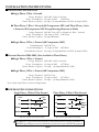
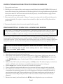
F IND
OUT MORE
ON THE WEB .
W I L B U RC U RT I S . C O M
W ILBUR C URTIS C OMP
ANY , I NC.
OMPANY
GEM-312IL & -300IL Satellite Brewer Instructions
GEMINI
INTERLOCK
COFFEE
SERVICE
MANUAL
Nº 11
Series
10/19/99SYSTEMS
BREWING
Gemini 300IL
Gemini 312IL
WILBUR CURTIS COMPANY
Montebello, CA 90640
C
ISO 9001 REGISTERED
F-1901.:65 14.4
P1
REV.A
FOR THE LATEST SPECIFICATIONS AND INFORMATION GO TO
WWW.WILBURCURTIS.COM
SHIPPING CARTON CONTENTS
The shipping carton contains the following standard items:
GEMINI 312IL
QTY
1
2
2
4
2
1
2
70
2
ITEM
Brewer (Dash Numbers Indicate Variations)
Brew Cone with Handle
Wire Basket
Adjustable Legs, 4"
Satellite Server with Lid (Less Faucet)
3/8 Male X 3/8 Compression Elbow
"S" Faucet, Self Closing
Paper Filters
Satellite Faucet Guard
Part Nº
GEM 312IL
WC-3311
WC-3301
WC-3500
GEM-3
WC-2805
WC-1800
GEM-6
WC-6417
GEMINI 300IL
QTY
1
1
1
4
1
1
1
35
1
ITEM
Brewer(Dash Numbers Indicate Variations)
Brew Cone with Handle
Wire Basket
Adjustable Legs, 4"
Satellite Server with Lid
3/8 Male X 3/8 Compression Elbow
"S" Faucet, Self Closing
Paper Filters
Satellite Faucet Guard
Part Nº
GEM-3OOIL
WC-3311
WC-3301
WC-3500
GEM-3
WC-2805
WC-1800
GEM-6
WC-6417
Index
SUBJECT
PAGE
Installation Instructions - Electrical Data . . . . . . . . . . . .
1
Electrical Data GEMINI 312IL . . . . . . . . . . . . . . . . . 1
Electrical Data GEMINI 300IL. . . . . . . . . . . . . . . . . . 1
Plumbing Information . . . . . . . . . . . . . . . . . . . .
2
Set-up Instructions . . . . . . . . . . . . . . . . . . . . .
2
Grinder Hook-up . . . . . . . . . . . . . . . . . . . . . .
3
Programming . . . . . . . . . . . . . . . . . . . . . . . . 3
Operating the Interlock System . . . . . . . . . . . . . . . . 4
By-pass Operation . . . . . . . . . . . . . . . . . . . . . . 5
By-pass Adjustment . . . . . . . . . . . . . . . . . . . . . 5
Hot Water Dispensing . . . . . . . . . . . . . . . . . . . . 5
Coffee Requirements - Type & Quantity . . . . . . . . . . . .
6
Satellite Holding Temperature . . . . . . . . . . . . . . . .
6
Care & Maintenance . . . . . . . . . . . . . . . . . . . .
6
Cleaning . . . . . . . . . . . . . . . . . . . . . . . . . . 6
High Temperature Reset Thermostat . . . . . . . . . . . . . . 7
Troubleshooting . . . . . . . . . . . . . . . . . . . . . 7-11
Function of Gemini . . . . . . . . . . . . . . . . . . . . . 1 1
Gemini 312IL Illustrated Parts List . . . . . . . . . . . . . 12-15
Gemini 300IL Illustrated Parts List . . . . . . . . . . . . . 15-16
Gemini Satellite & Warmer, Illustrated Parts List . . . . . . . 17-18
Gemini Satellite Parts List . . . . . . . . . . . . . . . . . 20-21
Wiring Diagram - GEM 5 & 8 . . . . . . . . . . . . . . . . . 2 1
Wiring Diagram - Gemini 312IL Single Phase . . . . . . . . . . 2 2
Wiring Diagram - Gemini 300IL Single Phase . . . . . . . . . . 2 3
Warranty . . . . . . . . . . . . . . . . . . . . . . Back Cover
-
INSTALLATION INSTRUCTIONS
Electrical Data for GEM-312IL
Single Phase, 3 Wire + Ground
Voltage Required: 208/240V (120V to Neutral)
Power Consumption: 29 Amps at 220V
6300 Watts
Circuit Breaker Capacity: 40 Amps (30 Amp Minimum on 220V, 40 Amp if 208V)
Three Phase, 3 Wire + Ground (All Components 220V) and Three Phase, 4 wire
+ Ground. (All Components 120V Except Heating Elements in Tank)
Voltage Required: 208/240 Volts (120V to Neutral in 4 Wire + Ground)
Power Consumption: 16.6 Amps at 220V 6300 Watts
Circuit Breaker Capacity: 20 Amps Minimum.
Single Phase, 2 Wire + Ground (All Components 220V)
Voltage Required: 208/240 Volts
Power Consumption: 29 Amps at 220V 6300 Watts
Circuit Breaker Capacity: 40 Amps. (30 Amp Minimum on 220V, 40 Amp if 208V)
Electrical Data for GEM-300IL (Not Available in Three Phase)
Single Phase, 3 Wire + Ground
Voltage Required: 208/240V (120V to Neutral)
Power Consumption: 19 Amps at 220V
4175 Watts
Circuit Breaker Capacity: 30 Amps (20 Amps Minimum if 220V)
Single Phase, 2 Wire + Ground (All Components 220V)
Voltage Required: 208-240 Volts
Power Consumption: 19 Amps at 220V
4175 Watts
Circuit Breaker Capacity: 30 Amps. (20 Amps Minimum if 220V)
Note: Read Serial Plate for Power Requirements
POWER SUPPLY CONNECTIONS
Single Phase, 3 Wires* Plus Ground
POWER SUPPLY
WIRES
BREWER
WIRES
Red
L1
Blue
L1
Red
L2
220V
220V
120V
Neutral
BREWER
WIRES
POWER SUPPLY
WIRES
220V
208-240V
L2
Three Phase, 3 Wires* Plus Ground
White
L3
Black
Striped
Blue
GND
Ground
* Do not use less than #10 AWG
* Do not use less than #12 AWG
! WARNING To prevent shock, the body of the brewer must be securely grounded. A
GREEN grounding screw, located inside the electrical box is provided for this purpose.
Page 1
PLUMBING INFORMATION
A 3/8" pipe thread X 3/8" compression 90º elbow is supplied with this brewer for water line connection.
Use 3/8" O.D. copper tubing to connect water to the machine.
We recommend using a good water filter in the line before entering the brewer. Some type of water
strainer MUST be used to obtain a trouble-free operation. The removable top back panel of the brewer
has two 1/4 dia. screws to facilitate mounting the water filter.
CAUTION: DO NOT connect this brewer to hot water. The inlet valve is not rated for hot water.
SET-UP INSTRUCTIONS
After the brewer has been properly installed to comply with all local electrical and plumbing codes, proceed to start the brewing operation as follows:
1.
Remove top cover. Locate and remove lid from the heating tank. Make sure the primary
thermostat (part no. WC-517) is turned off. The thermostat is item no. 88 in Gemini
312IL parts list and item no. 58 in the Gemini 300IL parts list.
2.
Open the water supply valve.
3.
Turn main breaker on. Turn toggle switch in back of brewer on. At this
time the water will start flow in into the heating tank. Turn On/Off switch in front panel
on. This will energize the controls and the switches will light up.
4.
Place clean satellite on warmer deck.
5.
Push warmer switch to ON position to preheat the satellite.
NOTE: The satellite must be preheated for ten minutes before brewing coffee.
Never brew coffee in a cold satellite. The coffee temperature will drop instantly.
6.
When the heating elements are covered with water, turn primary thermostat, WC-517, on.
7.
When water shuts off, reinstall the tank lid.
Allow 15 minutes for the water to reach 200°F inside the heating tank. After the initial heat up, the
temperature recovery is instantaneous. You may brew continuously.
Page 2
INSTRUCTIONS FOR CONNECTING TO INTERLOCK GRINDER
1. Place grinder near brewer.
2. With the top cover removed, take out the empty strain relief from hole labeled INTERLOCK in back of
brewer. Pass the end of the grinder interlock cable through this hole. On single head brewers plug the cable
directly into timer WC-642 or into the interlock cable (if present). On dual head brewers plug the interlock cable into the timer interlock cable.
3. Place strain relief onto cable outside of brewer. Connection to timer cable should be inside brewer for
maximum durability. Use a plier to squeeze the strain relief to slip it into the hole. Plug linecord into
power outlet.
4. To program the grinder, refer to the manual supplied with the grinder.
PROGRAM SETTING - GEMINI 312IL & GEMINI 300IL BREWER
IMPORTANT: Following the Set-up Instructions, your brewer is ready to brew coffee. This brewer is
set-up at the factory to brew 12, 24 or 36 cups of coffee. This will be fine for most brewing requirements. If you would like to adjust this setting, continue with the following programming instructions.
The amount of coffee brewed is controlled by timers that limit the duration of water flow coming from the
heating tank. Both brewers have preset switches marked 12 CUPS, 24 CUPS and 36 CUPS. Typically,
you would set up the 12 CUP brew switch to brew around twelve cups, the 24 CUP switch to brew about
twentyfour cups, etc.. However, the actual quantity of coffee depends on how you program the brewer.
1234567890123456789012345678901212345678901234567890123456789012123456789012345678901234567890121234
1234567890123456789012345678901212345678901234567890123456789012123456789012345678901234567890121234
1234567890123456789012345678901212345678901234567890123456789012123456789012345678901234567890121234
1234567890123456789012345678901212345678901234567890123456789012123456789012345678901234567890121234
1234567890123456789012345678901212345678901234567890123456789012123456789012345678901234567890121234
! CAUTION: As with all electrical equipment, caution must be taken to avoid electrical
1234567890123456789012345678901212345678901234567890123456789012123456789012345678901234567890121234
1234567890123456789012345678901212345678901234567890123456789012123456789012345678901234567890121234
1234567890123456789012345678901212345678901234567890123456789012123456789012345678901234567890121234
1234567890123456789012345678901212345678901234567890123456789012123456789012345678901234567890121234
shock. The following steps will also involve working with hot water. Scalding may occur
1234567890123456789012345678901212345678901234567890123456789012123456789012345678901234567890121234
1234567890123456789012345678901212345678901234567890123456789012123456789012345678901234567890121234
1234567890123456789012345678901212345678901234567890123456789012123456789012345678901234567890121234
if care is not taken against spilling.
1234567890123456789012345678901212345678901234567890123456789012123456789012345678901234567890121234
1234567890123456789012345678901212345678901234567890123456789012123456789012345678901234567890121234
1234567890123456789012345678901212345678901234567890123456789012123456789012345678901234567890121234
1. Open the top cover (loosen four slotted screws).
2. The Gemini 312IL brewer has two timers (right and left). The Gemini 300IL brewer has only one
timer. On the timer there is a small function switch marked RUN and PROGRAM. Push the switch
to the PROGRAM position. On the Gemini 312IL, you can program the timers one at a time or
together.
3. Push the ON/OFF switch, on the front panel, to the ON position. The indicator lights, over the brew
switches, will flash on the side that is controlled by the timer(s) that you're working on.
4. Slide an empty brew cone into the brew rails, beneath the sprayhead.
5. Place a graduated container under the brew cone to measure the water coming from the sprayhead.
6. Choose the brew switch that you want to set and press once. Hot water will start to spray in the brew
cone and into the measuring container. As soon as the amount of water has reached the desired level,
press the brew switch again. This stops the brew cycle. This brew switch is now set for the amount of
liquid in the container. Repeat this procedure on the other switches until all of them have been programmed.
7. Return to the timer(s) and switch back to the RUN position. Replace the top cover on the unit.
Page 3
OPERATING THE INTERLOCK SYSTEM
Make sure that the Set-up Instructions, are complete before
attempting to operate the Interlock System.
1 . Push the Brew Cone into Place on the
Grinder.
Decide on Regular or Decaf. Push 12, 24 or
36 Cup Switch. Coffee Will Start to Grind.
2 . When the Grinder Stops, Slide the Brew
Cone into the Rails on the Brewer. On the
312 you may use either side, as both are
interlocked.
3 . Push the Lighted Brew Switch with the
Lighted Indicator. Coffee Will Start to Brew.
To Interrupt a Brew Cycle, Push the ON/OFF
Switch.
12345678901234567890123456789012123456789012345678901234567890121234567890123456789012
12345678901234567890123456789012123456789012345678901234567890121234567890123456789012
12345678901234567890123456789012123456789012345678901234567890121234567890123456789012
12345678901234567890123456789012123456789012345678901234567890121234567890123456789012
12345678901234567890123456789012123456789012345678901234567890121234567890123456789012
! CAUTION: Once the brew cycle has finished be sure the brew cone is com12345678901234567890123456789012123456789012345678901234567890121234567890123456789012
12345678901234567890123456789012123456789012345678901234567890121234567890123456789012
12345678901234567890123456789012123456789012345678901234567890121234567890123456789012
pletely empty before attempting to lift the satellite server from the brewer.
12345678901234567890123456789012123456789012345678901234567890121234567890123456789012
12345678901234567890123456789012123456789012345678901234567890121234567890123456789012
Scalding may occur from hot liquid still in the brew cone. Allow it to drip out
12345678901234567890123456789012123456789012345678901234567890121234567890123456789012
12345678901234567890123456789012123456789012345678901234567890121234567890123456789012
12345678901234567890123456789012123456789012345678901234567890121234567890123456789012
a few minutes just to be safe.
12345678901234567890123456789012123456789012345678901234567890121234567890123456789012
12345678901234567890123456789012123456789012345678901234567890121234567890123456789012
NOTE: The brewer and grinder may be operated independently, without
Inerlock connection.
Page 4
BY-PASS FLOW OPERATION
These brewers are set at the factory to brew 12, 24 or 36 cups of coffee. The 36 cup brew cycle has a by-pass valve
that will by-pass up to 40% of the water around the coffee grounds. If you desire to change this setting for any
reason, you may do so by adjusting the by-pass valve (part no. WC-844) on the Gemini 312IL (item no. 57*) and
on the Gemini 300IL (item no. 56)
BY-PASS FLOW ADJUSTMENT
1. Place satellite, without cover, on the warmer deck.
2. Slide brew cone in just far enough to catch all the water pouring from the
sprayhead, but leaving the by-pass outlet exposed.
3. Hold a measuring cup under the by-pass outlet and push brew switch.
Count 15 seconds; then push the ON/OFF switch to stop the cycle.
4. Count the number of ounces collected in the measuring cup. Determine
the percentage of by-pass by comparing your total with the ounces in the
Brew Cycle Chart, below. Total flow in 15 seconds is 6.5 to 8.3 oz.
5. To change the quantity of water that is by-passed, turn the adjustment
screw clockwise for less water. Turning it counter clockwise will increase
the flow of water. You may have to adjust the brew timer to maintain the
total quantity of coffee brewed into the satellite.
6. The last column of the Brew Cycle Chart gives you the approximate timer
settings for 36 cups. Make your timer adjustments as detailed on page 3.
7. Check the coffee level in the satellite. The coffee should come up to one
inch from the top edge of the satellite liner or measure approximately 1.5
gallons.
BREW CYCLE CHART (36 CUPS ONLY)
BY-PASS SETTING
FOR 15 SECONDS
PERCENT OF
BY-PASS
PERCENT TO
SPRAYHEAD
TOTAL TIME
BREW CYCLE
3 oz.
60%
70%
5½ min.
2¼ oz.
40%
30%
1½ oz.
20%*
80%
6 min.
7 min.
The settings in this table are approximate. Variations may occur, requiring finer adjustment before the final setting.
HOT WATER DISPENSING
The hot water spout lets you draw piping hot water for tea, soups, and other profitable "instants" anytime - even
during the brew cycle.
To use this feature, place a cup under the hot water spout centered on the lower front panel. Press the HOT
WATER switch on the upper front panel and hold it. Hot water will flow from the spout. Releasing the switch
stops the flow of hot water.
*Factory setting.
Page 5
COFFEE REQUIREMENTS
TYPE
These Gemini brewers are designed to brew any type of ground coffee. Instant or concentrated liquid coffee is
not recommended. Before attempting to use these coffee products, consult your coffee provider.
QUANTITY
Because so many different grinds of coffee are available today, you should consult your coffee company. Generally
6 to 8 ounces are used to brew 1½ gallons (36 cups). Referring to the by-pass flow adjustment section will show
you how to adjust the brew to your tastes.
SATELLITE HOLDING TEMPERATURE
Under normal conditions, brewed coffee sitting in a satellite will maintain it's temperature at approximately 180ºF
until consumed when left on the warmer deck of the brewer and the satellite has been pre-heated. The same applies
when a satellite is removed from the brewer and placed on an electric warmer stand (GEM-5 or GEM-8). If the
satellite is removed from the brewer and placed on a non-electric stand, the coffee will keep it's temperature at
180ºF to 170ºF for an extended period of time depending on surrounding ambient temperature.
CARE AND MAINTENANCE OF BREWER
Regular and preventive maintenance is essential in keeping your Gemini system looking and working like new.
!
IMPORTANT
When cleaning your Gemini System, do not use cleansers, bleach liquids, powders or any other substance that
contains chlorine. These products promote corrosion and will pit the stainless steel. USE OF THESE PRODUCTS
WILL VOID WARRANTY.
PREVENTIVE MAINTENANCE
1. Remove the sprayhead (item no. 25 on the Gemini 312IL or item no. 27 on the Gemini 300IL) from the brewer and
clean it once a week or more often in heavy lime areas.
2. Clean the seat cups (item #32 on GEM-3 satellite parts breakdown) in the faucet once a week and replace if cracked
or leaking.
3. Remove the hot water spout aerator (item #13, Gemini 312IL and Gemini 300IL); clean it once a week.
4. The inside of the heating tank should be de-limed at least every six months and more often in areas with especially
hard water.
CLEANING
Using a daily routine of cleaning the external parts of the Gemini 300IL or Gemini 312IL brewing system should maintain it's new appearance and insure the good flavor of the coffee.
1. Wipe off any spills, dust or debris from the exterior surfaces.
2. Clean the outside of the brewer and satellite with stainless steel polish. Coarser agents may
scratch the machine.
3. Slide out brew cone. Rinse thoroughly with clean water.
4. Remove the sprayhead and clean. Clean around the dome area, wiping with a non toxic cleaner.
5. Clean the brew cone rails with a damp cloth or brush. Dry thoroughly with clean cloth.
Page 6
POWER DISCONNECT
Before removing any panels or starting any repairs, turn off power running to the brewer, from the main circuit
breaker panel.
The toggle switch, in back of the coffee brewer, turns on the power up to the contactor only. One half of this relay,
(part no. WC-400R) and one line to the heating elements remain electrified. With the toggle switch turned off, the
coffee brewer is inoperable.
The ON/OFF switch, on the front panel, turns off the power to all the controls: timers lights, warmer and dump
valves. The heating elements and the liquid level controls will remain electrified.
HIGH TEMPERATURE RESET THERMOSTAT
The function of this thermostat, part no. WC-508, is to automatically cut off the power to the heating element in
case the water level drops too low. This condition may be caused by failure in the solid state water level control, the
probe or the inlet valve. When the water level is so low that the elements are exposed, the very hot temperature will
cause the reset button to pop out to prevent the element from burning out. When the low water condition has
been corrected, push in the RED button on the thermostat to reset. You will know it has reset by a distinct "click".
! CAUTION
Do not turn off water supply while the brewer is still on. The coil on the water inlet valve will burn.
TROUBLESHOOTING
To help serviceman encountering a problem in the field make a rapid diagnosis, we have separated the three basic
functions of these brewers:
1
WATER LEVEL
CONTROL
2
HEAT SUPPLY
3
BREWING
OPERATION
When you are called for service, first find out which one of these three functions are failing and concentrate in
checking only the components involved. DO NOT remove any components until you know which is not working.
WATER LEVEL CONTROL OPERATION
These instructions and component part numbers are for 120V control circuits. If you have a 220V unit, see wiring
diagram furnished with your unit for part numbers and expect 208-240 where 110-120V is written.
Components involved:
1. Solid State Water Level Control Board
2. Water Inlet Valve
Part No. WC-608
Part No. WC-826 (Gemini 312IL)
Part No. WC-827 (Gemini 300IL)
3. Water Level Probe
Part No. WC-5502
Under normal conditions and operation the water level in the tank should not drop more than ½" from the
probe tip. If the water level is lower than this, the tank is not being refilled fast enough. Check your water line
and water filter. Cleaning of the water line or replacing the filter may be necessary.
Page 7
PROBLEM: NO WATER IS ENTERING THE HEATING TANK
TANK INLET VALVE TEST
TURN POWER OFF. Disconnect wires from the water inlet valve coil and connect a two wire lamp cord to
the terminals. Plug it into a 115 volt outlet. This will activate the coil. Water should flow into the tank when
you plug it in and stop when you pull out the plug. If it does, the valve is working normally.
If the water inlet valve passes this test, the problem may be with the probe or water level control board.
If the water inlet valve does not pass this test, the solenoid coil may have failed. Replace the coil. The valve
may have an obstruction blocking the flow of water. Disassemble and clean it out or replace the valve.
PROBETEST
If the valve is okay yet you are still not getting water flow into the tank, check the probe: Turn on the power
to the brewer. Check inside the heating tank to make sure the water is not touching the probe. Pull the wire
terminal off the probe rod. If water starts flowing into the tank, the probe may be grounded due to excessive
liming or condensation. Remove it, clean and wrap it tight with Teflon tape. Leave only 1/8" of the tip
exposed. If water still does not flow in after pulling the terminal off the probe, the problem may be in the
solid state liquid level control (LLC) board.
LIQUID LEVEL CONTROL TEST
Check the board as follows:
A. Make sure there is power input to the LLC board at
the terminals 2 & 3. Your voltmeter should read
115 volts. It should read the same at terminals 1 & 3.
This is the output power to electrify the coil of
the solenoid valve.
The lack of voltage at terminals 1 & 3 will indicate
that the L.L.C. board is not working properly.
B. Make sure all wire connections to the L.L.C. board
are tight.
C. The grounding plate, behind the board, should make
contact with the L.L.C. mounting bracket.
The board will not work or will work erratically if it is
not grounded properly.
GROUNDINGPLATE
PROBE
NEUTRAL
HOT
VALVESOLENOID
PROBLEM: WATER WON'T STOP FLOWING INTO THE HEATING TANK .
You must follow the same procedure to check the 3 components but in reverse.
WATER INLET VALVE TEST
Turn off all power to the brewer. Observe water level inside the heating tank. If it rises, the water inlet
valve is leaking. Clean it out or replace it.
PROBETEST
At the time the tank is overflowing pull the wire terminal off the probe rod and touch the metal top of the
tank. If the water stops flowing, the probe circuit lost continuity due to extreme liming condition, lack of
minerals in the water (very soft water), or loose connection.
A. Remove the probe and clean it.
Page 8
B. Disconnect ORANGE wire from T4 of water level board and check for continuity from the
terminal of this wire to the tip of the probe inside the heating tank. If there is no continuity, find
the point where continuity is broken and correct it.
C. If the tank is full but water continues to flow in, check for voltage at the water inlet valve coil. If
there is voltage, the water level control board is not working properly. Check it for loose ground
connection (see top of page, step B & C Liquid Level Control Test for lack of water). Replace
board if test shows the water level control is defective.
HEAT SUPPLY OPERATION
Components Involved:
1. High Temp. Cut-off Thermostat (WC-508)
2. Primary Thermostat (WC-517)
3. Power Relay, Contactor (WC-400R)
4. Heating Elements (WC-906),
5. Toggle Switch (WC-102)
6. Fuse (WC-1500)
PROBLEM: WATER STAYS COLD
HIGH TEMPERATURE RESET THERMOSTAT TEST
A. Make sure there is power at terminals 2 and 4 (points A) of high temperature reset thermostat.
Volt meter should read 220V between these two terminals. You should also read 220V at terminals
1 and 3 (points B) of the high temperature reset thermostat. Lack of voltage at these terminals will
indicate the thermostat is open. Push in the red reset button. If terminals 1 and 3 still lack voltage,
check the primary thermostat and contactor (steps B, C and D). The contacts of both must be
closed to allow current flow to terminals 2 and 1 of the high temperature reset thermostat. If
the contacts of the primary thermostat or the high temperature reset thermostat are open,
check toggle switch.
TOGGLE SWITCH AND FUSE TEST
B. Clamp one leg of your meter on terminal 1, point D, of the contactor.
C. Keep one leg of the meter on terminal 1 at point D on contactor. Make sure primary thermostat
dial is turned all the way clockwise. With the other leg of the voltmeter, take a reading at points I
and J of the thermostat. Your meter should read 110 to 120 volts. If no voltage is present at
point J replace this thermostat (WC-517). It is not closing the contacts that allow current to
flow to the contactor coil.
CONTACTOR TEST
D. Keep one leg of the meter on terminal 1 at point D of contactor and with the other leg touch the
screw, terminal no. 2, of same contactor at point K. If the primary thermostat is working properly,
the meter should read 110 to 120 volts: the thermostat is open.
Page 9
If you do not read 110 to 120V the contactor coil may be burned, remaining open and interrupting the flow of current to heating elements. The contactor may need to be replaced.
PROBLEM: WATER IS NOT HOT ENOUGH
Components to test:
1. Heating Elements . . . . . . . . . . . . . . . .
2. Primary Thermostat . . . . . . . . . . . . . .
Part No. WC-906
Part No. WC-517
A. On the Gemini 312IL, to verify if all three heating elements are working at full capacity, place a
clamp of your ammeter around the BROWN wire L. The dial should display approximately 29
amps if all three elements are working. A reading of 19 amps means only two elements are working. Disconnect the wires from the elements terminals and check each one for continuity. This will
determine which one is open or burned and if they need replacing.
A method of determining which element is burned; clamp an ammeter at each jumper between
the elements.
With the Gemini 300IL, you have only two heating elements in the heating tank, therefore a
reading of 19 amps is normal. Place a clamp of your ammeter around the BLACK wire L. You
should read 19 amps. If not, disconnect the wires from the element terminals and check each one
for continuity. This will determine which is open or burned and if they need replacing.
A method of determining which element is burned; clamp an ammeter at each jumper between
the elements.
B. The primary thermostat should be in the ON position (rotated fully clockwise).
PROBLEM: WATER DOES NOT COME FROM THE SPRAYHEAD WHEN THE BREW
SWITCH IS PRESSED
Components Involved:
1. On/Off Switch . . . . . . . . . . . . .
Part No. WC-121
2. Brew Switch . . . . . . . . . . . . . .
Part No. WC-122
3. Timer . . . . . . . . . . . . . . . . .
Part No. WC-642
4. Dump Valves . . . . . . . . . . . . . .
Part Nos. WC-820 & WC-821
All problems in the brewing function of these brewers are easily located and corrected due to the simplicity of
the components. Just follow the current flow from point to point as indicated in the wiring diagram.
We assume that the automatic refill and heat supply functions are working correctly.
A.
Be sure the heating tank is full of water up to the probe tip, if it is not, find the problem and
correct it. See "Water Level Control Operation".
B.
Pushing the ON/OFF switch to the ON position will send power to the two brew timers
Page 10
(through terminals 4B and 5B of the switch). With the switch in the ON position, check for
voltage between any of the above mentioned terminals and any neutral terminal (WHITE
wire). You should read 110 to 120 volts. If not, the ON/OFF switch is defective. Replace it.
C. Pushing any of the 12 cup, 24 cup, or 36 cup brew switches will open the dump valve, sending
hot water to the sprayhead. If the valve fails to open; check the coil for continuity. If the coil
checks out okay, then the brew timer is the likely cause of the problem. The brew timer energizes the coil on the valve, opening the valve for whatever brew switch you've selected.
PROBLEM: WATER IS COMING FROM THE AREA AROUND THE SPRAYHEAD WITHOUT
THE BREW SWITCH BEING PRESSED.
1. Determine if the water is flowing from the sprayhead or the overflow hole.
A. If water is leaking from the sprayhead, then the dump valve is the problem. Clean the inside of
the valve. Check the diaphragm for holes or tears in the rubber cup. Look for any solid particles that
may be preventing the valve from closing. You may have to replace the valve.
B. If water is leaking from the overflow hole, then the tank is overflowing. Refer to the trouble shooting
section, "PROBLEM: WATER WILL NOT STOP FLOWING INTO THE HEATING TANK."
FUNCTION OF THE GEMINI
B
A
G
1
1
D
C
123
123
E
H
F
123456789012345678901234567890121234567890123
123456789012345678901234567890121234567890123
123456789012345678901234567890121234567890123
1234567
1234567 1234567
12345678
123456789012345678901234567890121234567890123
1234567
1234567 1234567
12345678
1234567
1234567
12345678
The water in the hot water tank is maintained at the same level at all times by a
sensor called the water level probe A.
This controls the water inlet valve G.
When a brew switch is pushed, the brew
cycle is started: The dump valve B, is
opened by the brew timer, allowing hot
water to be sprayed over the ground
coffee in the brew basket C.
During the brew cycle, part of the water
coming from the tank is diverted away
from the ground coffee as by-pass; eventually mixing with the brewed coffee in
the Satellite. The by-pass is adjustable at
the by-pass valve D. By-pass is important
because it allows the user to control the
"balance" of the coffee, thereby optimizing the flavor of the coffee.
The hot water valve F, dispenses hot
water for tea, instant beverages, or soups.
A warmer element, H, keeps the coffee
in the Satellite at the proper temperature.
Page 11
Page 12
GEMINI 312IL PARTS BREAKDOWN
B
Page 13
C
GEMINI 312IL PARTS BREAKDOWN
B
C
Gemini 312IL - Parts List
INDEX
Nº
1
2
3
4
5
6
7
8
9
10
11
12
13
14
15
16
17
17A
18
19
20
21
22
23
24
25
26
27
28
29
30
31
32
33
34
35
36
37
38
39
40
41
42
43
44
45
46
48
49
50
51
53
54
PART
Nº
WC-5421
WC-3301
WC-3311
WC-3963
WC-4003
WC-3201
WC-5423
WC-38310
WC-37102
WC-6732-1
WC-4201
WC-2912BK
WC-2946
WC-2947
WC-4308
WC-5424
WC-3965
WC-3965-01
WC-3500
WC-4439
WC-5310
WC-4205
WC-37122
WC- 400R
WC-1411
WC-2936
WC-2945
WC-4213
WC-5829
WC-4503
WC- 122
WC- 121
WC- 200
WC- 123
WC- 124
WC-6301
WC-5482
WC-4616
WC-2805
WC- 847
WC- 830
WC-3765
WC-3249
WC-1501
WC-1500
WC- 102
WC-3810
WC- 517
WC-38149
WC-1412
WC-4509
WC- 647
WC-4329
DESCRIPTION
TOP COVER . . . . . . . . . . . . . . . . . . . . . . . . . . . . . . . . .
WIRE BASKET, PB-2 . . . . . . . . . . . . . . . . . . . . . . . . . . . . . . .
BREW CONE WITH HANDLE . . . . . . . . . . . . . . . . . . . . . . . . . . .
LABEL, REMOVE BASKET SLOWLY . . . . . . . . . . . . . . . . . . . . . . . .
RETAINER NUT . . . . . . . . . . . . . . . . . . . . . . . . . . . . . . . . . .
HANDLE FOR BREW CONE . . . . . . . . . . . . . . . . . . . . . . . . . . . .
WARMER DECK, NO ELEMENTS . . . . . . . . . . . . . . . . . . . . . . . . .
LABEL, CAREFUL HOT SURFACE . . . . . . . . . . . . . . . . . . . . . . . . .
KIT, WARMER ELEMENT 100W 120V . . . . . . . . . . . . . . . . . . . . . . . .
STRAP, WARMER ELEMENT GEMS . . . . . . . . . . . . . . . . . . . . . . . .
NUT, HEX KEP, 8-32 . . . . . . . . . . . . . . . . . . . . . . . . . . . . . . . .
SPOUT, HOT WATER, NO SPLASH (OPTIONAL) . . . . . . . . . . . . . . . . . . .
AERATOR, FEMALE, CHROME PLT'D . . . . . . . . . . . . . . . . . . . . . . .
ADAPTOR, MALE AERATOR . . . . . . . . . . . . . . . . . . . . . . . . . . .
WASHER, ½" I.D. INTERNAL LOCK . . . . . . . . . . . . . . . . . . . . . . . .
BRACKET, FAUCET SUPPORT . . . . . . . . . . . . . . . . . . . . . . . . . .
PANEL, TOP AND BOTTOM . . . . . . . . . . . . . . . . . . . . . . . . . . .
LABEL, SWITCH PANEL W/O HOT WATER . . . . . . . . . . . . . . . . . . . . .
LEG, 4" ADJUSTABLE COUNTER . . . . . . . . . . . . . . . . . . . . . . . . .
SCREW, 6-32x¼ PHIL PAN HD SS . . . . . . . . . . . . . . . . . . . . . . . . . .
TUBING, 5/16" I. D., SILICONE . . . . . . . . . . . . . . . . . . . . . . . . . .
NUT, ¼" NPS, BRASS . . . . . . . . . . . . . . . . . . . . . . . . . . . . . .
KIT, DUMP VALVE RIGHT . . . . . . . . . . . . . . . . . . . . . . . . . . . . . .
POWER RELAY, 120V, 50 AMP . . . . . . . . . . . . . . . . . . . . . . . . . .
BUSHING, SNAP IN, 5/8" . . . . . . . . . . . . . . . . . . . . . . . . . . . . .
SPRAY HEAD (RED PLASTIC) . . . . . . . . . . . . . . . . . . . . . . . . . . .
FLOW RESTRICTOR . . . . . . . . . . . . . . . . . . . . . . . . . . . . . . .
NUT, LOCK 5\8" . . . . . . . . . . . . . . . . . . . . . . . . . . . . . . . . .
COVER, FRONT W/A GEM-312 . . . . . . . . . . . . . . . . . . . . . . . . . . .
SCREW, 8-32 x ½" . . . . . . . . . . . . . . . . . . . . . . . . . . . . . . . .
ROCKER SWITCH, BREW, 125V . . . . . . . . . . . . . . . . . . . . . . . . .
ROCKER SWITCH, ON/OFF, 125V . . . . . . . . . . . . . . . . . . . . . . . .
INDICATOR LIGHT, 115V . . . . . . . . . . . . . . . . . . . . . . . . . . . . .
ROCKER SWITCH, WARMER, 125V . . . . . . . . . . . . . . . . . . . . . . . .
ROCKER SWITCH, HOT WATER, 125V . . . . . . . . . . . . . . . . . . . . . .
BRACKET, UPPER TANK SUPPORT . . . . . . . . . . . . . . . . . . . . . . . .
PANEL, BACK TOP WRAP . . . . . . . . . . . . . . . . . . . . . . . . . . . .
SCREW, 1/4-20x½ PHILLIPS PAN HEAD SS . . . . . . . . . . . . . . . . . . . . .
ELBOW, COMPRESSION, 3/8" x 3/8" . . . . . . . . . . . . . . . . . . . . . . .
VALVE, INLET 2 GPM 120V 10W . . . . . . . . . . . . . . . . . . . . . . . . . .
WASHER, FLOW, 1.0 GMP . . . . . . . . . . . . . . . . . . . . . . . . . . . .
KIT, REBIULD FOR WATER INLET VALVE . . . . . . . . . . . . . . . . . . . . .
GUARD, SWITCH . . . . . . . . . . . . . . . . . . . . . . . . . . . . . . . . .
FUSE HOLDER . . . . . . . . . . . . . . . . . . . . . . . . . . . . . . . . . . .
FUSE, 5 AMP . . . . . . . . . . . . . . . . . . . . . . . . . . . . . . . . . . .
SWITCH, TOGGLE, 125V, 20 AMPS . . . . . . . . . . . . . . . . . . . . . . . .
LABEL, CAUTION DO NOT TURN ON POWER... . . . . . . . . . . . . . . . . . .
THERMOSTAT . . . . . . . . . . . . . . . . . . . . . . . . . . . . . . . . . .
LABEL, WARNING DO NOT INSTALL... . . . . . . . . . . . . . . . . . . . . . .
CORD GRIP, 3/4" FOR METAL CORD . . . . . . . . . . . . . . . . . . . . . . . .
SCREW, 10-32 x 5/8" GRN . . . . . . . . . . . . . . . . . . . . . . . . . . . .
CABLE, INTERLOCK TIMER . . . . . . . . . . . . . . . . . . . . . . . . . . . .
WASHER, EXTERNAL LOCK #8 . . . . . . . . . . . . . . . . . . . . . . . . . .
Page 14
Gemini 312IL - Parts List
INDEX
Nº
55
56
57
58
59
60
61
62
63
64
65
66
67
68
69
70
71
72
73
74
75
76
77
78
79
80
82
83
84
85
86
PART
Nº
WC- 608
WC- 642
WC-37130
WC-2977
WC-37121
WC-4405
WC-2215
WC-3766
WC- 419
WC-4380
WC-5432
WC-5431
WC-2948
WC-4314
WC-4320
WC-29009
WC-5502
WC-2938
WC-4212
WC-5409
WC-4306
WC-3689
WC- 522
WC- 906
WC-2956
WC-2935
WC-5661
WC-43058
WC-4319
WC-4381
WC-43801
DESCRIPTION
LIQUID LEVEL CONTROL BOARD, LLC . . . . . . . . . . . . . . . . . . . . . .
TIMER, TRI-BREW, 120V . . . . . . . . . . . . . . . . . . . . . . . . . . . . .
KIT, VALVE BY-PASS . . . . . . . . . . . . . .
FITTING, SPRAYHEAD . . . . . . . . . . . . . . . . . . . . . . . . . . . . . . .
KIT, DUMP VALVE LEFT . . . . . . . . . . . . . . . . . . . . . . . . . . . .
SCREW, PAN HEAD, 6-32 x 7/8" . . . . . . . . . . . . . . . . . . . . . . . . . .
TEE 1/4" WROT TEE . . . . . . . . . . . . . . . . . . . . . . . . . . . . . . . .
KIT, REPAIR FOR VALVE WC-821 . . . . . . . . . . . . . . . . . . . . . . . . .
COIL FOR EATON VALVE, 115V . . . . . . . . . . . . . . . . . . . . . . . . . .
SHOCK GUARD FOR LLC . . . . . . . . . . . . . . . . . . . . . . . . . . . . .
HEATING TANK COMPLETE . . . . . . . . . . . . . . . . . . . . . . . . . . .
HEATING TANK WITH BRASS FITTINGS ONLY . . . . . . . . . . . . . . . . . .
FITTING, OVERFLOW . . . . . . . . . . . . . . . . . . . . . . . . . . . . . . .
GROMMET, SILICONE . . . . . . . . . . . . . . . . . . . . . . . . . . . . . . .
O' RING . . . . . . . . . . . . . . . . . . . . . . . . . . . . . . . . . . . . . .
FITTING, INLET . . . . . . . . . . . . . . . . . . . . . . . . . . . . . . . . . .
PROBE, WATER LEVEL . . . . . . . . . . . . . . . . . . . . . . . . .
FITTING, HEX PROBE . . . . . . . . . . . . . . . . . . . . . . . . . . . . . . .
NUT, 5/8" JAM . . . . . . . . . . . . . . . . . . . . . . . . . . . . . . . . . .
CLIP, THERMOSTAT BULB TO HEATING ELEMENT . . . . . . . . . . . . . . . . .
WASHER, TEFLON 9/16" I.D. . . . . . . . . . . . . . . . . . . . . . . . . . . .
INSULATION, WRAP TANK . . . . . . . . . . . . . . . . . . . . .
THERMOSTAT, RESET . . . . . . . . . . . . . . . . . . . . . . . . . . . . . .
HEATING ELEMENT, 2000W, 220V . . . . . . . . . . . . . . . . . . . . . . . .
FITTING, TUBE, HOT WATER OUTLET . . . . . . . . . . . . . . . . . . . . . . .
FITTING TANK OUTLET . . . . . . . . . . . . . . . . . . . . . . . . . . . . . .
LID ASSEMBLY FOR HEATING TANK, INCLUDING GASKET . . . . . . . . . . . .
PLUG, DRAIN PP RED . . . . . . . . . . . . . . . . . . . . . . . . . . . . . .
CLAMP, HOSE S/S . . . . . . . . . . . . . . . . . . . . . . . . . . . . . . . .
SHOCK GUARD, RESET THERMOSTAT . . . . . . . . . . . . . . . . . . . . . .
SHOCK GUARD, HEATING ELEMENT TERMINALS . . . . . . . . . . . . . . . . .
PRICES SUBJECT TO CHANGE WITHOUT NOTICE
Page 15
GEMINI 300IL PARTS BREAKDOWN
Page16
GEMINI 300IL PARTS BREAKDOWN
Page17
Gemini 300IL - Parts List
INDEX
Nº
1
2
3
4
5
6
7
8
9
10
11
12
13
14
15
16
17
17A
18
19
20
21
22
23
24
25
26
27
28
29
30
31
32
33
34
35
36
37
38
39
40
41
42
43
44
45
46
47
48
49
50
51
52
53
54
PART
Nº
DESCRIPTION
TOP COVER . . . . . . . . . . . . . . . . . . . . . . . . . . . . . .
WC-5450
WIRE BASKET, PB-2 . . . . . . . . . . . . . . . . . . . . . . . . . . .
WC-3301
BREW CONE WITH HANDLE . . . . . . . . . . . . . . . . . . . . . . .
WC-3311
LABEL, REMOVE BASKET SLOWLY . . . . . . . . . . . . . . . . . . . .
WC-3963
NUT, RETAINER . . . . . . . . . . . . . . . . . . . . . . . . . . . . .
WC-4003
HANDLE FOR BREW CONE . . . . . . . . . . . . . . . . . . . . . . . .
WC-3201
WARMER DECK, NO ELEMENTS . . . . . . . . . . . . . . . . . . . . . .
WC-5451
LABEL, CAUTION HOT SURFACE . . . . . . . . . . . . . . . . . . . . .
WC-3831
KIT, WARMER ELEMENT 120V, 100W . . . . . . . . . . . . . . . . . . . .
WC-37102
WC-6732-1 STRAP FOR WARMER ELEMENT . . . . . . . . . . . . . . . . . . . . .
NUT, KEP, 8-32 . . . . . . . . . . . . . . . . . . . . . . . . . . . . . .
WC-4201
WC-2912BK HOT WATER SPOUT ASSEMBLY (OPTIONAL) . . . . . . . . . . . . . . . .
AERATOR, FEMALE . . . . . . . . . . . . . . . . . . . . . . . . . . . .
WC-2946
ADAPTER, MALE . . . . . . . . . . . . . . . . . . . . . . . . . . . . .
WC-2947
WASHER, INTERNAL LOCK, 1/2" I.D. . . . . . . . . . . . . . . . . . . .
WC-4308
NUT, LOCK, NPS, 1/4" . . . . . . . . . . . . . . . . . . . . . . . . . .
WC-4205
PANELS TOP AND BOTTOM . . . . . . . . . . . . . . . . . . . . . . .
WC-39009
WC-39009-01 LABEL, SWITCH PANEL W/O HOT WATER GEM300IL . . . . . . . . . . . .
BRACKET FAUCET SUPPORT . . . . . . . . . . . . . . . . . . . . . . .
WC-5424
LEG, ADJUSTABLE 4" . . . . . . . . . . . . . . . . . . . . . . . . . .
WC-3500
KIT, DUMP VALVE RIGHT . . . . . . . . . . . . . . . . . .
WC-37122
KIT, REPAIR USE ON WC-820, WC-821,WC-844,WC-880E . . . . . . . . . .
WC-3766
COIL, 115V, FOR EATON VALVE . . . . . . . . . . . . . . . . . . . . .
WC- 419
TUBING, SILICONE, 5/16" I.D. . . . . . . . . . . . . . . . . . . . . . .
WC-5310
WC- 400R POWER RELAY, 115V, 50A . . . . . . . . . . . . . . . . . . . . . . . .
COVER, FRONT . . . . . . . . . . . . . . . . . . . . . . . . . . . . .
WC-5452
BUSHING, SNAP-IN, 5/8" . . . . . . . . . . . . . . . . . . . . . . . . .
WC-1411
SPRAYHEAD, RED . . . . . . . . . . . . . . . . . . . . . . . . . . . .
WC-2936
RESTRICTOR, FLOW . . . . . . . . . . . . . . . . . . . . . . . . . . .
WC-2945
NUT, LOCK 5/8" . . . . . . . . . . . . . . . . . . . . . . . . . . . . .
WC-4213
SCREW, PAN HEAD, 8-32 x 1/2" . . . . . . . . . . . . . . . . . . . . .
WC-4503
VALVE, WATER INLET . . . . . . . . . . . . . . . . . . . . . . . . . .
WC- 827
WASHER, FLOW, 1 GPM FOR WC- 827 . . . . . . . . . . . . . . . . . .
WC- 848
KIT, REPAIR, FOR WC- 827 VALVE . . . . . . . . . . . . . . . . . . . .
WC-3700
SCREW, 1/4-20x½ PHILLIPS PAN HEAD SS . . . . . . . . . . . . . . . . .
WC-4616
FITTING, ELBOW, COMPRESSOR, 3/8" x 3/8" . . . . . . . . . . . . . . .
WC-2805
SCREW, 6-32x¼ PHIL PAN HD SS . . . . . . . . . . . . . . . . . . . . . .
WC-4439
LIGHT, INDICATOR, 115V . . . . . . . . . . . . . . . . . . . . . . . .
WC- 200
SWITCH, ROCKER, HOT WATER, 115V . . . . . . . . . . . . . . . . . .
WC- 124
SWITCH, ROCKER, ON/OFF, 115V . . . . . . . . . . . . . . . . . . . .
WC- 121
SWITCH, ROCKER, BREW, 115V . . . . . . . . . . . . . . . . . . . . .
WC- 122
SWITCH, ROCKER, WARMER, 115V . . . . . . . . . . . . . . . . . . .
WC- 123
LABEL, WARNING . . . . . . . . . . . . . . . . . . . . . . . . . . . .
WC-38149
GUARD, SWITCH . . . . . . . . . . . . . . . . . . . . . . . . . . . . .
WC-3234
SWITCH, TOGGLE, 125V, 80A . . . . . . . . . . . . . . . . . . . . . .
WC- 102
LABEL, GROUND . . . . . . . . . . . . . . . . . . . . . . . . . . . . .
WC-3812
GRIP, CORD, 7/8" . . . . . . . . . . . . . . . . . . . . . . . . . . . .
WC-1408
LABEL, WIRING WARRANTY . . . . . . . . . . . . . . . . . . . . . . .
WC-3820
FUSE, 5 AMP . . . . . . . . . . . . . . . . . . . . . . . . . . . . . .
WC-1500
FUSE HOLDER . . . . . . . . . . . . . . . . . . . . . . . . . . . . . .
WC-1501
COVER, ELECTRIC BOX . . . . . . . . . . . . . . . . . . . . . . . . . .
WC-5840
LABEL, CAUTION . . . . . . . . . . . . . . . . . . . . . . . . . . . . .
WC-3810
SCREW, 8-32 x 1/4 . . . . . . . . . . . . . . . . . . . . . . . . . . . .
WC-4501
TIMER, TRI-BREW . . . . . . . . . . . . . . . . . . . . . . . . . . . .
WC- 642
SCREW, PAN HEAD, 6-32 x 7/8 . . . . . . . . . . . . . . . . . . . . . .
WC-4405
Page 18
.
. .
. .
. . .
. .
Gemini 300IL - Parts List
INDEX
Nº
55
56
57
58
61
62
63
64
65
66
67
69
70
71
72
73
74
75
76
77
78
79
80
81
82
83
84
85
86
87
PART
Nº
WC-2977
WC-37130
WC-6556
WC- 517
WC- 608
WC-4380
WC-4329
WC-6301
WC-4320
WC-2948
WC-5661
WC-4212
WC-4314
WC-2938
WC-5502
WC-2935
WC- 508
WC-4306
WC- 906
WC-5409
WC-29009
WC-2956
WC-43801
WC-4381
WC-4398
WC-4319
WC-3691
WC-5453
WC-5454
WC- 648
DESCRIPTION
FITTING, SPRAYHEAD . . . . . . . . . . . . . . . . . . . . . . . . . . . . . . .
KIT, VALVE BY-PASS . . . . . . . . . . . . . .
PANEL, TOP WRAP BACK G300IL . . . . . . . . . . . . . . . . . . . . . . . . . .
THERMOSTAT . . . . . . . . . . . . . . . . . . . . . . . . . . . . . . . . . . . .
CIRCUIT BOARD, LIQUID LEVEL CONTROL . . . . . . . . . . . . . . . . . . . .
GUARD, SHOCK FOR L.L.C. . . . . . . . . . . . . . . . . . . . . . . . . . . . . .
WASHER, LOCK, EXTERNAL #8 . . . . . . . . . . . . . . . . . . . . . . . . . . .
BRACKET, UPPER TANK SUPPORT . . . . . . . . . . . . . . . . . . . . . . . . .
O' RING, 1/2" . . . . . . . . . . . . . . . . . . . . . . . . . . . . . . . . . . . .
FITTING, TANK OVERFLOW . . . . . . . . . . . . . . . . . . . . . . . . . . . . .
LID ASSEMBLY FOR HEATING TANK . . . . . . . . . . . . . . . . . . . . . . . .
NUT, JAM, 5/8" BRASS . . . . . . . . . . . . . . . . . . . . . . . . . . . . . . .
GROMMET, RUBBER, FDA (9101) . . . . . . . . . . . . . . . . . . . . . . . . . .
FITTING, HEX PROBE . . . . . . . . . . . . . . . . . . . . . . . . . . . . . . . .
PROBE, WATER LEVEL . . . . . . . . . . . . . . . . . . . . . . . . . . . . . . .
FITTING, TANK OUTLET . . . . . . . . . . . . . . . . . . . . . . . . . . . . . . .
THERMOSTAT, RESET, MR-4 . . . . . . . . . . . . . . . . . . . . . . . . . . . .
WASHER, TEFLON, 9/16" I.D. . . . . . . . . . . . . . . . . . . . . . . . . . . . .
HEATING ELEMENT, 2000W, 220V . . . . . . . . . . . . . . . . . . . . . . . . .
CLIP, THERMOSTAT TO HEATING ELEMENT . . . . . . . . . . . . . . . . . . . . .
FITTING, INLET . . . . . . . . . . . . . . . . . . . . . . . . . . . . . . . . . .
TUBE ASSEMBLY, HOT WATER TANK . . . . . . . . . . . . . . . . . . . . . . . .
SHOCK GUARD FOR HEATING ELEMENT TERMINALS . . . . . . . . . . . . . . . .
SHOCK GUARD FOR RESET THERMOSTAT . . . . . . . . . . . . . . . . . . . . .
PLUG, DRAIN, TEFLON . . . . . . . . . . . . . . . . . . . . . . . . . . . . . . .
CLAMP, HOSE, S/S . . . . . . . . . . . . . . . . . . . . . . . . . . . . . . . . .
INSULATION, GEM-230A/300IL . . . . . . . . . . . . . . . . . . . . .
HEATING TANK WITH FITTINGS ONLY . . . . . . . . . . . . . . . . . . . . . . .
HEATING TANK COMPLETE . . . . . . . . . . . . . . . . . . . . . . . . . . . . .
CABLE, INTERLOCK TIMER . . . . . . . . . . . . . . . . . . . . . . . . . . . . .
PRICES SUBJECT TO CHANGE WITHOUT NOTICE
Page 19
ILLUSTRA
TED PPAR
AR
TS BREAKDOWN GEM-3, -5, -8
ILLUSTRATED
ARTS
5
6
7
8
11
4
9
2
12
1
17
10
15
14
13
3
INDEX PART
Nº
Nº
GEM-5
WC-1201
WC- 114R
GEM 3
WC-3307
WC-5622
WC-2102
WC-2010C
WC-2025
SATELLITE WARMER STAND,115V . . . .$124.00
.
POWER CORD 6’ 18/3 BLK . . . . . . . . . .10.00
SWITCH, ROCKER 120V RED . . . . . . . .13.00
.
SATELLITE SERVER 1½ GAL . . . . . . . 239.00
.
LID GEMINI SATELLITE . . . . . . . . . . . 26.50
LID, SATELLITE PLASTIC GEM3 (OPTIONAL)
18.00
GAUGE GLASS ASSEMBLY, 8” C . . . . . . 11.00
SHIELD, 8 INCH GAUGE GLASS . . . . . . . 4.50
GAUGE GLASS, 8 INCH . . . . . . . . . . .
Wiring Diagram Gem -5 & -8
WARMER ELEMENT
WHITE
INDEX PART
Nº
Nº
9
10
11
11A
12
13
14
15
WC-2007
WC-1901
WC-1800
WC-1841
WC-3705
GEM 4
WC-3503
WC-37102
120 Volts,
DESCRIPTION
90 Watts
BLACK
RED
WARMER
SWITCH
5B 4B
3A
Page20
LIST
PRICE
BRACKET, GAUGE GLASS FORMED . . . .$5.50
.
SHANK, FAUCET D&T CHROME . . . . . .24.00
FAUCET S’ NONLOCKING . . . . . . . . . 36.00
FAUCET, "ESP" BLACK NONLOCKING (OPTNL)
20.00
KIT FAUCET S’ SERIES . . . . . . . . . . 76.00
.
SATELLITE STAND . . . . . . . . . . . . . 1.50
LEG, SCREW BUMPER 3/8"-16 STD . . . . 8.00
KIT, WARMER ELEMENT 100W 120VAC . . .
POWER CORD
WHITE
GRN
1
2
3
4
5
5A
6
7
8
LIST
PRICE
DESCRIPTION
Page21
Page 22
Page23
Page 24
WARRANTY
We hereby certify that the products manufactured by the Wilbur Curtis Company, Inc., are, to thebest of our knowledge,
free from all defects and faulty workmanship.
The following warranties and conditions are applicable:
1. 1 Year Parts & Labor from Date of Purchase from Factory: This warranty covers all electrical parts, fittings
and tubing.
2. 40 Months or 40, 000 Pounds of Coffee on a set of Grinding Burrs. (ADS Grinders)
3. 3 Years from Date of Purchase: This warranty covers electronic control boards and leaking or pitting of a
stainless steel body of a Brewer or Urn.
4. 90 Days from Date of Purchase: On replacement parts that have been installed on out of warranty equipment
All in-warranty service calls must have prior authorization from the manufacturer. For an RMA (Return Merchandise
Authorization) number, call the Technical Service Department at 1-800-995-0417. The Wilbur Curtis Company will allow
up to 100 miles, round trip, per in-warranty service call.
CONDITIONS & EXCEPTIONS
The warranty covers original equipment at time of purchase only. The Wilbur Curtis Company, Inc., assumes no
responsibility for substitute replacement parts installed on Curtis equipment that have not been purchased from the
Wilbur Curtis Company. Inc The Wilbur Curtis Company will not accept any responsibility if the following conditions are not
met. The warranty does not cover and is void under these circumstances:
1) Improper operation of equipment. The equipment must be used for its designed and intended
purpose and function.
2) Improper installation of equipment. This equipment must be installed by a professional,
certified technician and must comply with all local electrical, mechanical and plumbing codes.
3) Wilbur Curtis Company will not be responsible for the operation of equipment at other than the
stated voltages on the serial plate.
4) Abuse or neglect (including failure to periodically clean or remove lime accumulations).
Manufacturer is not responsible for variation in equipment operation due to excessive lime or
local water conditions.
5) Replacement of items subject to normal use and wear. This shall include, but is not limited to,
light bulbs, shear disks, “0” rings, gaskets, canister assemblies. whipper chambers and plates,
mixing bowls, agitation assemblies and whipper propellers.
6) Any faults resulting from inadequate water supply. This includes, but is not limited to, excessive or low water pressure, and inadequate or fluctuating water flow rate.
7) All repairs and/or replacements are subject to our decision that the workmanship or parts were
faulty and the defects showed up under normal use.
8) All labor shall be performed during regular working hours. Overtime charges are the responsibility of the owner.
9) Charges incurred by delays, waiting time, or operating restrictions that hinder the service
technician’s ability to perform service is the responsibility of the owner of the equipment.
This includes institutional and correctional facilities.
10) All claims under this warranty must be submitted to the Wilbur Curtis Company Technical
Service Department before return of the unit to the factory.
11) All equipment returned to us must be repackaged properly in the original carton. No units will
be accepted if they are damaged in transit due to improper packaging.
12) Damaged in transit.
13) The resetting of safety thermostats and circuit breakers, programming and temperature
adjustments are the responsibility of the equipment owner.
NO UNITS OR PARTS WILL BE ACCEPTED WITHOUT A RETURN MERCHANDISE AUTHORIZATION (RMA).
RMA NUMBER MUST BE MARKED ON THE CARTON OR SHIPPING LABEL.
All in-warranty service calls must be performed by an authorized service center, where service is available. Call the factory
for location near you.
WILBUR CURTIS CO., INC.
6913 Acco St., Montebello, CA 90640-5403 USA
Phone: 800/421-6150
Fax: 323-837-2410
Technical Support Phone: 800/995-0417 (M-F 5:30A - 4:00P PST)
Web Site: www.wilburcurtis.com
E-Mail: [email protected]
Printed in U.S.A.
FOR THE LATEST SPECIFICATION INFORMATION GO TO WWW.WILBURCURTIS.COM
8/27/03 F-1901 rev B