1
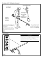
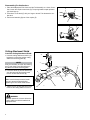
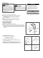
SHINDAIWA OWNER’S/OPERATOR’S MANUAL
Model: 65001
MULTI-PURPOSE
TRIMMER TOOL
Minimize the risk of injury to yourself and others!
Read this manual and familiarize yourself with the
contents. Always wear eye and hearing protection
WARNING! when operating this unit.
X7502880002
01/11
Introduction
The Multipurpose Trimmer Tool has
been designed and built to deliver
superior performance and reliability
without compromise to quality, comfort,
safety or durability.
While every attempt has been made
to provide the latest information about
your Shindaiwa product, there may be
some differences between your attachment and what is described here.
As an owner/operator, you’ll soon
discover for yourself why Shindaiwa is
simply in a class by itself!
ECHO, Inc. reserves the right to make
changes to products without prior
notice, and without obligation to make
alterations to units previously manufactured.
Contents
PAGE
Attention Statements........................... 2
Safety.................................................. 3
Product Description............................. 5
IMPORTANT!
The information contained in these
instructions describes units available at
the time of publication.
PAGE
Specifications...................................... 5
Assembly............................................. 5
Operation............................................. 7
PAGE
Maintenance........................................ 8
Troubleshooting Guide........................ 9
IMPORTANT!
The operational procedures described in this manual are intended to help you get the most from this unit as well as to
protect you and others from harm. These procedures are guidelines for safe operation under most conditions, and are not
intended to replace any safety rules and/or laws that may be in force in your area. If you have questions regarding your
Shindaiwa hand held power equipment, or if you do not understand something in this manual, contact your local Shindaiwa
dealer for assistance. You may also contact Shindaiwa at the address printed on the back of this Manual.
Attention Statements
Throughout this manual are special “attention statements”.
WARNING!
DANGER!
A statement preceded by the triangular attention symbol and the word
“DANGER” contains information
that should be acted upon to prevent serious injury or death.
CAUTION!
A statement preceded by the triangular attention symbol and the word
“WARNING” contains information
that should be acted upon to prevent serious bodily injury.
A statement preceded by the word
“CAUTION” contains information
that should be acted upon to prevent mechanical damage.
NOTE:
IMPORTANT!
A statement preceded by the word
“IMPORTANT” is one that possesses
special significance.
A statement preceded by the word
“NOTE” contains information that is
handy to know and may make your job
easier.
International Symbols
Read and follow this manual,
make sure anyone using the
pruner does likewise. Failure
to do so could result in serious
personal injury or machine failure. Keep this manual for future
reference.
Always wear a hard hat to
reduce the risk of head injuries
during operation of this machine.
In addition, always wear eye and
hearing protection. Shindaiwa
recommends wearing a face
shield as additional face and eye
protection.
2
Keep bystanders at
least 50 ft. away.
Do not operate this tool if you are
tired, ill or under the influence of
alcohol, drugs, or medication.
Do not operate this machine with a
brushcutter blade.
Safety
This machine operates at very high speeds and has the
potential to do serious damage if misused, abused or mishandled. To reduce the risk of injury, you must maintain
control at all times, and observe all safety precautions
during operation. Never permit a person without training
or instruction to operate this machine!
NOTE:
For specific maintenance and safety information about your
Multipurpose Tool Carrier, consult the owner's manual
provided with it. If it has been lost or misplaced, contact a
Shindaiwa dealer for a replacement.
Operating Precautions
■■This Shindaiwa trimmer tool is
specifically designed for use on
the Shindaiwa Multipurpose Tool
Carrier. Installation and/or use on
any other model, brand or type
of power tool is not approved by
Shindaiwa. Attempts to use on
non-approved models can damage
the equipment and cause accidents, serious injury or death.
■■Always make sure the Multipurpose Trimmer Tool is properly
installed and firmly tightened
before operation.
■■Never extend trimming line beyond
the length specified for your unit.
WARNING!
■■Never use a cracked or warped
cutting attachment: replace it with
a serviceable one and make sure
it fits properly.
■■Before starting the engine, make
sure the cutting attachment is not
contacting anything.
■■Always stop the engine immediately and check for damage if
you strike a foreign object or if the
machine becomes tangled. Do not
operate with broken or damaged
equipment.
■■Stop the machine immediately if
it suddenly begins to vibrate or
shake. Inspect for broken, missing or improperly installed parts or
attachments.
■■Never transport the machine or set
it down with the engine running. An
engine that’s running could be accidentally accelerated causing the
cutting attachment to rotate
■■ALWAYS keep a Solid Stance.
Maintain footing and balance at all
times. Do not stand on slippery,
uneven or unstable surfaces. Do
not work in odd positions or on ladders. Do not over reach.
The Properly Equipped Operator
ALWAYS protect yourself from
hazards such as thorny brush
and flying debris by wearing
gloves and close fitting clothing
that covers arms and legs.
Never wear shorts. Don't wear
loose clothing or items such as
jewelry that could get caught
in machinery or underbrush.
Secure long hair so it is above
shoulder level.
Keep a proper
footing and do not
overreach—maintain your balance
at all times during
operation.
Wear sturdy footwear with
nonslip soles to provide good
footing. Steel-toed safety boots
are recommended. Never
operate unit bare-footed!
Always wear eye protection such as goggles or
safety glasses. Wear hearing protection devices
and a broad-brimmed hat or helmet.
Always operate with both
hands firmly gripping the unit.
Keep away from the rotating
trimmer line at all times, and
never lift a moving attachment
above waist-high.
Always make sure the appropriate cutting attachment
shield is correctly installed
and in good condition.
3
Be Aware of the Working Environment
Avoid long-term operation in very hot or
very cold weather.
Be extremely
careful of slippery terrain, especially during
rainy weather.
If contact is made with a hard object, stop
the engine and inspect the cutting attachment for damage.
Be constantly alert for objects and debris
that could be thrown either from the rotating
cutting attachment or bounced from a hard
surface.
Make sure bystanders or observers outside the 50-foot “danger zone” wear eye protection.
Reduce the risk of
bystanders being struck
by flying debris. Make
sure no one is within
50 feet
(15 meters)—that’s
about 16 paces—of an
operating attachment.
When operating in rocky terrain
or near electric wires or fences,
use extreme caution to avoid contacting such items with the cutting
attachment.
Figure 3
Safety Labels
IMPORTANT!
Safety and Information Labels: Make sure all safety and information labels are undamaged, readable and up to date.
Immediately replace damaged or missing labels.
New labels are available through your local authorized
Shindaiwa dealer.
Figure 1
4
Product Description
Using the illustration as a guide, familiarize yourself with your machine and its various components. Understanding your machine helps ensure
top performance, long service life and safer
operation.
Multipurpose
Trimmer Tool
1 - Outer tube
2 - Gearcase
3 - Trimmer Head
4 - Cutting attachment shield
1
2
4
WARNING!
Do not make unauthorized
modifications or alterations to this unit
or its components.
3
Specifications
Length/Width/Height
Weight
Gearcase Lubrication
Gear Reduction
Gearcase Arbor Bolt Size
814 x 315 x 241 mm (32 x 12.4 x 11.8 in)
1.18 kg (2.6 lb)
Lithium based grease
1.286:1
7mm Left-hand thread
*Specifications are subject to change without notice.
Prior to Assembly
Before assembling, make sure you
have all the components required for a
complete unit:
■■Outer Tube/Main Shaft Assembly
■■Cutting Attachment Shield
■■Trimmer Head
■■Assembly Tool (s)
Carefully inspect all components for
damage.
IMPORTANT!
The terms “left”, “left-hand”, and “LH”;
“right”, “right-hand”, and “RH”; “front” and
“rear” refer to directions as viewed by the
operator during normal operation.
Assembly
Installing a Tool Attachment
1. Place the Multipurpose Tool Carrier (A) and the Tool Assembly (B) on a clean,
flat surface so that both assemblies fit end to end. The powerhead assembly
should be facing up, and the tool assembly should be positioned with the locking hole in the tube (C) end facing up.
A
G
F
CAUTION!
C
Keep the open ends of the tubes clean and free of Debris!
2. Slip off the protective cover from the end of the tool, and loosen the coupler
screw knob (D).
3. Insert the tool assembly into the coupler (E), with the tool decal facing up, until
the line of the decal is flush with the end of the coupler. Twist the tool back and
forth until you are sure it snaps in place by the coupler latch (F).
D
M23004
E
B
4. When the two tube halves are locked together, press down on the spring-loaded latch protector (G) and tighten the coupler screw knob.
5
Disassembling The Pole Sections
1. Place the Multipurpose Tool Carrier and the Tool Assembly on a clean, flat surface, loosen the coupler screw knob (D). The spring-loaded coupler protector
(G) should pop up.
E
G
2. Press down on the latch (F) with your finger or thumb. This releases the coupler latch.
3. Pull the tool assembly (B) out of the coupler (E).
M23005
D
M23006
Cutting Attachment Shield
Install the Cutting Attachment Shield.
G
1. Insert the cutting attachment shield (A)
between the outer tube and the cutting
attachment mounting plate (B).
NOTE:
F
It may be necessary to loosen the retaining
nut (C) and clamp screw (D)to adjust cutting attachment shield mounting plate.
A
E
2. Fit the two shims (E) and the bracket (F)
over the outer tube and loosely install
the four socket-head screws (G).
D
CAUTION!
Make sure the clamp screw and retaining nut is securely tightened before
tightening the four socket head screws.
3. Tighten the four socket-head cap screws
to secure the cutting attachment shield.
WARNING!
NEVER operate the trimmer without the
cutting attachment shield installed and
tightly secured!
6
E
C
1025
B
Trimmer Head
Install the Trimmer Head.
A
1. Turn the trimmer over so that the gearcase output shaft faces UP.
2. Remove and discard the plastic retaining plug.
3. Rotate the tool holder and shaft until the notch in the holder (A)aligns with the
notch on the gearcase (B) flange, and use the long end of the hex wrench to
lock the output shaft in position.
B
4. While holding the hex wrench, thread the trimmer head onto the output shaft,
turning counter-clockwise.
5. Using hand pressure only, tighten the trimmer head firmly on the gearshaft.
IMPORTANT!
The trimmer head has a left-hand thread. Turn the trimmer head counter-clockwise
to install.
6. Remove the hex wrench (C).
The Multipurpose Trimmer Tool should now be
completely assembled and ready for use.
C
Operation
CAUTION!
CAUTION!
Do not push the rotating line into
trees, wire fences or any material
that could tangle or break line ends.
Operation of trimmer without a cutting attachment shield and using
excessive line length can lead to
premature clutch failure.
Engine Operating Speeds
Operate the unit at full throttle while
cutting grass.
CAUTION!
Operation at low RPM can lead to
premature clutch failure.
Trimming and Mowing Grass
Hold the trimmer so the trimmer head is angled slightly into the area to be cut.
To ensure maximum trimmer-line service life, cut only with the tip of the trimmer
line. Cut grass by swinging the trimmer from left to right. Keep the trimmer head
horizontal.
Edging
Tilt the handle about 100° to the left (from horizontal) and move forward, holding
the trimmer vertically as shown.
7
Maintenance
IMPORTANT!
WARNING!
Before performing any maintenance, repair, or cleaning work on
the unit, make sure the engine and
cutting attachment are completely
stopped. Disconnect the spark plug
wire before performing service or
maintenance work.
WARNING!
Non-standard parts may not operate properly with your unit and may
cause damage and lead to personal
injury.
For detailed maintenance information
about your Multipurpose Tool Carrier, consult the owner's manual that
was provided with it. If it has been lost
or misplaced, contact Shindaiwa for a
replacement.
NOTE:
Using non-standard replacement parts
could invalidate your Shindaiwa warranty.
Prior to each work day, perform the following:
■■Check for loose or missing screws or components. Make
sure the cutting attachment is clean, free of debris and
securely fastened.
■■Check the entire machine for leaking fuel or grease.
■■Make sure that nuts, bolts, and screws (except carburetor adjusting screws) are tight.
50-hour Maintenance
Every 50 hours of operation
(more frequently in dusty or dirty conditions):
■■Remove the cutting attachment and the gear shaft collar (A), and press
new grease into the gear case until the old grease has been pushed out.
Use only lithium-base grease such as Shindaiwa Gear Case Lubricant or
equivalent.
New
Grease
Old
Grease
A
Loading Speed-Feed© Trimmer Line
1. Cut one piece of line to recommended length.
.080 (2.0 mm) dia. - 10’ (3 m)
.095 (2.4 mm) dia. - 10’ (3 m)
2
3
2. Align arrows on top of knob with openings in eyelets.
3. Insert one end of trimmer line into an eyelet, and push line equal distance through trimmer head.
4. Hold trimmer head while turning knob clockwise to wind line onto
spool until about 5” (13 cm) of each line remains exposed.
Trimmer head is now fully loaded and ready for operation.
4
8
IMPORTANT! When the wear indicators located at the bottom of the Speed-Feed head are worn
smooth, replacement of the cover or the entire Speed-Feed head is required.
Wear Indicators
Wear Indicators
Troubleshooting Guide
Indicadores
de desgaste
Symptom
Excessive vibration.
Cutting attachment will not
move.
ADDITIONAL PROBLEMS
Possible Cause
Warped or damaged attachment.
Inspect and replace attachment as
required.
Loose gearcase.
Tighten gearcase securely.
Bent main shaft/worn or damaged bushings.
Inspect and replace as necessary.
Shaft not installed in powerhead or gearcase.
Inspect and reinstall as required.
Broken shaft.
Consult with an authorized Shindaiwa servicing
dealer.
Damaged gearcase.
Engine idle too high.
Cutting attachment
moves
at engine idle.
Indicateurs
d’usure
RemedyIndicadores de desgaste
Broken clutch spring or worn clutch
spring boss.
Adjust idle. Check Specifications page for correct idle
speed.
Indicateurs
Replace spring/shoes as required,
check idled’usure
speed.
9
NOTES
10
NOTES
11
Servicing Information
Parts/Serial Number
Genuine Shindaiwa Parts and Assemblies for your Shindaiwa products are available only from an Authorized Shindaiwa
Dealer. When you do need to buy parts always have the Model Number and Serial Number of the unit with you. You can
find these numbers on the engine. For future reference, write them in the space provided below.
Model No. _____________ SN. ______________
Service
Service of this product during the warranty period must be performed by an Authorized Shindaiwa Service Dealer. For
the name and address of the Authorized Shindaiwa Service Dealer nearest you, ask your retailer or call: 1-877-986-7783.
Dealer information is also available on WWW.SHINDAIWA.COM. When presenting your unit for Warranty service/repairs,
proof of purchase is required.
Consumer Product Support
If you require assistance or have questions concerning the application, operation or maintenance of this product you may
call the Shindaiwa Consumer Product Support Department at 1-877-986-7783 from 8:30 am to 4:30 pm (Central Standard
Time) Monday through Friday. Before calling, please know the model and serial number of your unit.
Warranty Registration
To ensure trouble free warranty coverage it is important that you register your Shindaiwa equipment by filling out the warranty registration card supplied with your unit. Registering your product confirms your warranty coverage and provides a direct
link if we find it necessary to contact you.
Additional or Replacement Manuals
Replacement Operator and Parts Catalogs are available from your Shindaiwa dealer or at WWW.SHINDAIWA.COM or
by contacting the Consumer Product Support Department (1-877-986-7783). Always check WWW.SHINDAIWA.COM for
updated information.
ECHO Incorporated.
400 Oakwood Road
Lake Zurich, IL 60047-1564 U.S.A.
Telephone: 1-877-986-7783
Fax: 1-847-540-8416
www.shindaiwa.com
Copyright© 2011 By Echo, Incorporated
All Rights Reserved.
Yamabiko Corporation
7-2 Suehirocho 1-Chome, Ohme,
Tokyo, 198-8760, Japan
Phone: 81-428-32-6118
Fax: 81-428-32-6145
T18800001001/T18800999999