1
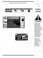
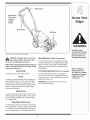
Safety • Assembly • Operation • Tips & Techniques • Maintenance
A
OF
• Troubleshooting • Parts Lists • Warranty
O
AL
Gas Lawn Edger-
Model Series 550
iMPORTANT
READ SAFETY
RULES AND iNSTRUCTiONS
CAREFULLY
BEFORE
OPERATION
Warning: This unit is equippedwith an internalcombustionengineand shouldnot be usedon or nearany unimprovedforest-covered,brushcoveredor grass-coveredland unlesstheengine'sexhaustsystemis equippedwith a sparkarrestermeetingapplicablelocalor statelaws(if any).
If a sparkarresteris used,it shouldbe maintainedin effectiveworkingorder by the operator.In theState of Californiathe aboveis requiredbylaw
(Section4442 of the CaliforniaPublicResourcesCode). Otherstatesmay havesimilarlaws.Federallaws applyon federallands.A sparkarrester
for the muffleris availablethroughyour nearestengineauthorizedservicedealeror contactthe servicedepartment,RO. Box361131Cleveland,
Ohio 44136-0019.
PRINTEDIN U.S.A
MTD LLC, P.O. BOX 361131 CLEVELAND,
OHIO 44136-0019
FORMNO. 769-02351
1/26/2006
This Operator's iVlanual is an important part of your new Edger. it will help you assemble, prepare,
and maintain the unit for best performance. Please read and understand what it says.
Table of Contents
1.
2.
3.
4.
5.
Safety Labels ..................................................
Safe Operation Practices ...............................
Assembling Your New Edger .........................
KnowYour Edger ............................................
Operation and Adjustment ............................
3
4
6
7
8
6. iVlaintainance
& Servicing ............................
7. Troubleshooting
............................................
8. Parts List .......................................................
Warranty
............................................
11
13
14
Back Cover
Finding and Recording IVlodel Number
BEFORE YOU BEING ASSEMBLING YOUR NEW EQUIPMENT, please locate the model plate on the equipment and
copy the informationto the sample model plate provided
to the right. You can locate the model plate by standing at
the operating position and looking down at the rear of the
Edger/Trencher.This informationwill be necessary to use the
manufacturer'sweb site, to obtain help from the Customer
Support Department, or when contacting an authorized service
dealer.
Model Number
Serial Number
MTD
LLC
P. O. BOX 361131
CLEVELAND,OH 44136
330-220-4683
,. www.mtdproducts.com
8oo-8oo-731
o.,
Customer Support
Please do NOTretum
the unit to the retailer from which it was purchased,
contacting Customer Support.
without
first
If you have difficulty assemblingthis product or have any questions regarding the controls, operation, or maintenanceof this
unit, you can seek help from the experts. Choose from the options below:
1. Visit www.mtdproducts.com.
Support menu option.
3. The engine manufacturer isresponsible for all enginerelated issueswith regards to performance, power-rating,
specifications, warranty and service. Please refer to the
engine manufacturer's Owner's/Operator's Manual, packed
separatelywith your unit, for more information.
Click on the Customer
2. Phone a Customer Support Representativeat
1-800-800-7310.
2
Please take a moment to review your safety labels.
WARNING
$321
Thissymbolpoints
out importantsafety
instructionswhich, if
not followed, could
endangerthe personal
safety and/or propertyof
yourself and others.Read
and follow all instructions
in this manual before
attempting to operate
this machine. Failure
to complywith these
instructionsmay result
in personalinjury.When
you see this symbol.
HEEDiTS WARNING
Your ResponsibUity:
Restrictthe use
of this powermachine
to personswho read,
understand
and follow the warnings
and instructions
in this manual
and on the machine.
3
WARNING: Engine Exhaust, some of its constituents, and certain vehicle components contain or emit chemicals known to State of Californiato cause cancer and
birth defects or other reproductiveharm.
DANGER: This machine was built to be operated according to the rules for safe operation in this
manual. As with any type of power equipment, carelessness or error on the part of the operator can
result in serious injury. This machine is capable of amputating hands and feet and throwing objects.
Failureto observe the following safety instructions could result in serious injury or death.
Children
RNING
This symbol points
out important safety
instructionswhich, if
not followed, could
endangerthe personal
i safety and/or property
of yourself and others.
Read and follow all
instructions in this manual before attempting to
operate this machine.
Failureto comply with
these instructions may
result in personal injury.
i When you see this
symbol.
HEED iTS WARNING
Your
i Responsibility
I
Restrict the use
i of this power machine
to persons who read.
understand
and follow the warnings
and instructions
in this manual
and on the machine.
13. Neverstore the machineor fuel containernear an open
flame,spark or pilot light as on a water heater,space heater,
furnace,clothesdryeror othergas appliances.
14. Toreducefire hazard,keeplawnedgerfree of grass,
leaves,or otherdebris build-up.Clean up oil or fuel spillage
and removeany fuel soakeddebris.
15. Allow a lawnedgerto cool at least 5 minutesbeforestoring.
Tragicaccidentscan occur if operatoris not alert to presence
of children.Childrenare oftenattractedto powerequipment
suchas lawnedgers.Theydo not understandthe dangers.
Neverassumethatchildrenwill remainwhereyou lastsaw
them.
1. Keepchildrenout of the mowingareaand underwatchful
careof a responsibleadultotherthanthe operator.
2. Be alert andturn lawnedgeroff if a childentersthe area.
3. Beforeand whilemovingbackwards,look behindanddown
forsmallchildren.
4. Useextremecare when approachingblind corners,
doorways,shrubs,trees,or otherobjectsthat may obscure
yourvisionof a child whomay run intothe lawnedger.
5. Keepchildrenawayfrom hot or runningengines.Theycan
sufferburnsfrom a hot muffler.
General Operation:
1. Readthis operator'smanual carefully inits entiretybefore
attemptingto assemblethis machine.Read,understand,
andfollowall instructionson the machineandin the
manual(s) beforeoperation.Be completelyfamiliar with
the controls andthe proper useof this machinebefore
operatingit. Keepthis manualin a safe place forfuture and
regularreferenceandfor orderingreplacementparts.
2. This machineis a precision pieceof powerequipment,not a
plaything.Therefore,exerciseextremecaution at all times.
Yourunit has been designedto performonejob: to edge
lawn.Do not use it for any otherpurpose.
3. Neverallow childrenunder 14yearsold to operatethis
machine.Children 14yearsold and overshould readand
understandthe instructionsinthis manualandshould
6. Neverallowchildrenunder14 yearsoldto operatean
edger.Children14 yearsold and overshouldreadand
understandoperationinstructionsandsafetyrulesinthis
manualandshouldbe trainedandsupervisedbya parent.
Operation
Safe Handling Of Gasoline:
1. Toavoid personalinjury or propertydamage use
extremecare in handlinggasoline,Gasolineis extremely
flammableand the vapors are explosive,Serious personal
injury can occur when gasolineis spilledon yourselfor
yourclotheswhichcan ignite,
2. Washyourskin andchangeclothesimmediately,
3. Useonly an approvedgasoline container,
4. Neverfill containersinsidea vehicle or on a truck or trailer
bedwith a plastic liner,Alwaysplace containerson the
groundawayfrom yourvehicle beforefilling.
5. Removegas-poweredequipmentfrom the truck or
trailer andrefuel it on the ground. Ifthis is not possible,
then refuelsuch equipmenton a trailer witha portable
container,ratherthan from a gasolinedispensernozzle.
6. Keepthe nozzle incontactwith the rim of the fuel tank or
containeropeningat all times until fueling is complete.Do
not use a nozzlelock-opendevice.
7. Extinguishall cigarettes,cigars, pipes andothersources
of ignition.
8. Neverfuel machineindoorsbecauseflammablevapors
will accumulateinthe area.
be trainedand supervisedby a parent.Onlyresponsible
individualswho arefamiliar withthese rulesof safe operation should be allowedto use this machine.
4. Tohelp avoid bladecontact or a thrown objectinjury,stay in
operatorzonebehind handlesand keepchildren,bystanders, helpersand pets at least 75 feetfrom lawnedgerwhile
it is in operation.Stop machineif anyoneentersarea.
5. Thoroughlyinspectthe area wherethe equipmentis to be
used. Removeall stones, sticks,wire, bones,toysand other
foreignobjectswhichcould be tripped overor picked up
andthrown bythe blade.Thrownobjectscan causeserious
personalinjury.
6. Alwayswearsafetyglasses or safetygogglesduringoperation andwhile performingan adjustmentor repairto protect
youreyes. Thrownobjectswhich ricochetcan causeserious
injury to the eyes.
7. Wearsturdy, rough-soledworkshoesand close-fitting
slacksandshirts. Shirtsand pantsthatcoverthe arms and
legs andsteel-toedshoesare recommended.Neveroperate
this machinein bare feet,sandals, slipperyor lightweight
(e.g. canvas)shoes.
8. Neverattemptto makeany adjustmentswhilethe engine
is running,exceptwhere specificallyrecommendedinthe
operator'smanual.
9. Toavoid personalinjury or propertydamage use extreme
care inhandlinggasoline.Gasolineis extremelyflammable
andthe vaporsare explosive.Serious personalinjury can
occurwhen gasolineis spilledon yourself or your clothes
9. Neverremovegas cap or addfuel whileengine is hot or
running. Allow engineto cool at least two minutesbefore
refueling.
10. Neverover fill fuel tank. Filltank to no morethan V2inch
belowbottomof filler neckto providefor fuel expansion.
11. Replacegasolinecap andtighten securely.
12. Ifgasolineisspilled,wipeit offthe engineandequipment.
Moveunitto anotherarea.Wait5 minutesbeforestarting
engine.
4
which can ignite.Washeryour skinand changeclothes
immediately.
10.Do not put handsor feet near rotatingparts.Contactwith
the rotatingbladecan amputatehandsandfeet.
11.The bladecontrol handle is a safetydevice.Neverbypass
its operation.Doingso, makesthe machineunsafeand may
cause personalinjury.
12.Neveroperatewithout bladeguard,debris shieldand blade
control handle in placeand working.
13.Neveroperatewith damagedsafetydevices.Failureto do
so, can resultin personalinjury.
14.Neverrun an engine indoorsor ina poorly ventilatedarea.
Engineexhaustcontainscarbonmonoxide,an odorlessand
deadlygas.
15.Do not operate machinewhileunderthe influenceof alcohol
or drugs.
16.Mufflerand engine becomehot andcan causea burn.Do
not touch.
the originalequipmentmanufacture's(O.E.M.)bladeonly,
listedin this manual."Useof partswhichdo not meetthe
originalequipmentspecificationsmay leadto improper
performanceand compromisesafety!"
4. Lawnedgerbladesare sharpand can cut.Wrapthe blade
or weargloves,and use extracautionwhenservicingthem.
5. Keepall nuts,bolts, andscrewstight to be surethe equipmentis insafe workingcondition.
6. Nevertamperwithsafetydevices.Checktheir proper
operationregularly.
7. Afterstrikinga foreignobject,stop the engine,disconnect the sparkplug wire andgroundagainstthe engine.
Thoroughlyinspectthe lawnedgerfor any damage.Repair
the damagebeforestartingandoperatingthe lawnedger.
8. Neverattemptto makea wheel or cuttingheightadjustmentwhilethe engine is running.
9. Manycomponentson your new edgercan wearwith
continueduse. For safetyprotection,frequentlycheck
all edgercomponentsandreplaceimmediatelywith
originalequipmentmanufacturer's(O.E.M.)parts only,
listed inthis manual."Use of parts whichdo not meetthe
originalequipmentspecificationsmay lead to improper
performanceand compromisesafety!"
10. Do not changethe enginegovernorsettingor overspeed
the engine.The governorcontrolsthe maximumsafe
operatingspeed of the engine.
11. Maintainor replacesafetylabels,as necessary.
12. Observeproperdisposallawsand regulations.Improper
disposalof fluidsand materialscan harmthe environment.
17.Neveroperatethis machinewithoutgood visibility or light.
Alwaysbe sure of yourfooting and keepa firmhold on the
handles.Walk, neverrun.
18.Do not operatethis machineif it has beendroppedor damaged. Returnmachineto your nearestauthorizedservicing
dealerfor examinationand repair.
29. Do not operatethis machinewitha damagedor excessively
worncutting blade.
20. Neverattemptto clear materialfrom the bladeguardwhile
the engine is running.Shutthe engine off, disconnectthe
spark plug wire andground againstthe engineto prevent
unintendedstarting.
21. Do not overloadmachinecapacityby attemptingto edge at
too fast of a rate.
22. Stay alert for unevensidewalks,terrain etc. Alwayspush
slowly overroughsurfaces.Do not use this machineon
gravel surfaces.
23. Do not operate machinein rain or wet soil conditions.
Alwaysoperatemachinefrom behindthe handlesand
positionyourself wherethe direct line of sight to cutting
blade is blockedby guards.
24. Alwaysstop enginewhen edging or trimming is delayedor
when transportingmachinefrom one locationto another.
Neverleave a runningmachineunattended.Stopthe
engine,disconnectspark plug wireand groundagainstthe
engine to preventunintendedstarting.
25. Only use parts andaccessoriesmade forthis machineby
the manufacturer.Failureto do so, can result in personal
injury.
26. Ifsituationsoccur whichare not coveredinthis manual,
WARNING
This symbol points
out important safety
instructions which, if
not followed, could
endangerthe personal
safety and/or property
of yourself and others.
Read and follow all
instructions in this manual before attempting to
operate this machine.
Failureto comply with
these instructions may
result in personal injury.
When you see this
symbol.
HEED iTS WARNING
use care and goodjudgment.Call 1-800-800-7310 for
CustomerSupportandthe name of your nearestdealer.
Your
Service
Responsibility
1. Neverrunan engineindoorsor in a poorlyventilatedarea.
Engineexhaustcontainscarbonmonoxide,an odorlessand
deadlygas.
2. Beforecleaning,repairing,or inspecting,makecertain the
bladeand all movingparts havestopped.Disconnectthe
spark plugwire andgroundagainstthe engineto prevent
unintendedstarting.
3. Checkthe bladeand enginemountingbolts at frequent
intervalsfor propertightness.Also,visuallyinspectblade
for damage(e.g.,bent, cracked,worn) Replacebladewith
Restrict the use
of this power machine
to persons who read.
understand
and follow the warnings
and instructions
in this manual
and on the machine.
5
IMPORTANT:This unit is shipped WITHOUTGASOLINE. Aftersettingup the unit, serviceenginewith
gasolineas instructedin the separateengine manual
packedwith your unit. Also be sure to service engine
with the oil enclosed with this unit as instructedin the
enginemanual.
NOTE: Referenceto right or left hand side of the
edger is observedfrom the operatingposition.
Assembling
Your NeW
Securing
i
the Handles
Removeand discardanypackagingcardboardthat may
be presentbetweentheupper handleand the lower
handle.
1. Depressthe bladecontrolat thetop of the upper
handleand pivot the upperhandleupwarduntil it
snapsinto place,Figure3-1.
Figure3-1:Unfoldhandleandtighten star knobs.
2. Tightenthe star knobs,which are locatedon boththe
left and rightsides of the handle.
WARNING
i
Attaching the Starter Rope
i
Locatethe ropeguide foundon the rightsideof the upper
handle.Loosen,but do NOTremove,the wing knobwhich
securesthe rope guideto the upper handle,Figure3-2.
The edgerbladewILL
rotatewhen thestarter
rope is pulled.
1. Standbehindthe unitand holdthe blade control
againstthe upperhandle.
2. Gentlypull the starterrope outof theengine.The
starterrope willnot pull out of the engineunlessthe
bladecontrol is depressedagainstthe upperhandle.
: _MPORTANT:
Th_s
unit
_1
is shipped WITHOUT
GASOMNE.Aftersett ng
3. Slip the starterropethroughthetop of the ropeguide.
enginewith gasoline as
instructed in the engine
manual packedwith your
unit. Be sureto service
ARNING:The edger blade WILL rotatewhen
the starter rope is pulled.
4. Tightenthewing knobwhich securesthe ropeguide to
the upperhandle.
Figure3-2:Pull recoilstarterthrough ropeguideand tighten.
engine
withtheoi_
enclosedwith this unit as
_nstructed
intheseparate
engineman,a!,
Specifications are
subject to changew thout
notification or obligation,
imagesmay not reflect
your exact model and are
for reference purposes
only,
6
Blade Control
Blade Depth
Control Lever
(Transport
Position
Shown)
Recoil Starter
Belt Guard
WARNING
Figure4-1:The maincomponentson the edger.
Bevel Adjustment Lever (if so equipped)
,_
WARNING: Be familiar with all controlsand
their properoperation. Know how to stop
the machine and disengage them quickly.
The beveladjustmentlever,if soequipped,is located
on thefront, left portionof the edger,behindthe edger
blade.It is usedto vary the angle of theedger blade
betweenone of threepositionsfor edging/trenchingor
bevelededging.
NOTE: Refer to the Engine Manualpackedwith your
edger for a detailed description of all engine-related
controls and components.
Recoil Starter
Curb Height Adjustment Lever (if so equipped)
The recoilstarteris usedto startthe engine.
The curbheightadjustmentlever,ifso equipped,is
foundon the rear portionof the edger.Whenplacedin
an applicablenotch,it aidsin stabilizingthe edger while
edginggrass alonga curb.
Primer
The primeris usedto pumpgas into thecarburetorand
aid in startingtheengine.Use it to start a coldengine,
but do not useit to restarta warmengineafter a short
shutdown.Refer to theEngineManualpackedwithyour
edger fora detaileddescriptionofall engine-related
controlsand components.
IMPORTANT:Becomefamiliarwith all the controls
beforeoperatingtheedger.
Blade Control
Locatedon the upperhandle,the bladecontrolmustbe
depressedagainstthe upperhandlein orderto operate
the unit. Releasingthe bladecontrolstopsthe engine
and the edgerblade.
Blade Depth Control Lever
The bladedepthcontrolleverislocatedon the rightside
of the upperhandle.It is usedto controlthe depthof the
cut. Thefurtherforwardthe blade depthcontrolleveris
moved,the deeperintothe soil the edgerbladewill cut.
7
Be familiar with all
controlsand their proper
operation.Know how to
stop the machine and
disengage them quickly.
Refer to the Engine
Manualpackedwith
your edger for a detailed
description of all enginerelated controtsand
components.
Edging
The operationof any edgercan result
in foreign objectsbeingthrown intothe
eyes, whichcan result in severeeye
damage. Alwayswearsafety glassesor eye shields.
Werecommend wide visionsafety mask for over
spectaclesor standardsafetyglasses.
and
To beginedging,proceedasfollows:
1. Movethe unit overto thearea to be edged,making
surethat the left rearwheelis on a hard surfaceand
the bladeis overthe area to be cut, Figure5-1.
. Movethe bladedepthcontrol leverto the left and place
intothe next lowernotch.Thenmakea pass alongthe
areato be edged beforeproceedingto the next notch.
Thefurther forwardthe bladedepthcontrolleveris
moved,the deeperor lowerthe bladewill cut intothe
ground.Severalpassesmaybe necessaryto obtain
the desireddepthof cut. Do not lowerthe blade more
thanone depth notchat a time withoutmakinga pass.
_hlt
ARNING: Do not lowerbladeif bladeis
over concrete,asphalt,rocks or the like.
The bladecanstrike the supportingsurface,resulting in personalinjuryor propertydamage.
Adding Gasoline
& Oil
Servicethe enginewithgasolineandoil as instructed
inthe EngineManualpackedwithyouredger.Read
instructions
carefully.
f
_IIL
WARNING:Never fill fuel tank indoors,
with enginerunningor until the enginehas
been allowed to cool for at least two minutes after
running.
Starting
WARNING
Do not lowerblade if
blade is over concrete,
asphalt,rocks, or the like.
The blade canstrikethe
supportingsurface,resulting in personalinjuryor
propertydamage.
Never fill fuel tank
indoors,with engine
runningor until the engine
has been allowedto cool
for at leasttwo minutes
afterrunning.
The Blade Control isa
safetydevice.Neverattempt
to bypassitsoperation.
NOTE: Refer to the Engine Manual packedwith your
edger for a detailed description of all engine-related
controls and components.
Tostarttheedger'sengine,proceedas follows:
1. Attachthe sparkplug wireto the spark plug.Make
certainthe metalcap on theend ofthe sparkplug
wireis fastenedsecurelyoverthe metal tip on the
spark plug.
2. Movethe bladedepthcontrol leverbackto the
STARTpositionin the adjacent(top) notch.
3. Depressthe primerbulbthreetimes, pausingtwo to
threesecondsbetweeneachpush. Incold weather
(below50°F/19°0), it may be necessaryto depress
the primerbulb fouror five times.
Figure5-1:Edgingexample.
3. Forbest results,proceedslowlyalongthepathbeing
edged,slowlymovingtheedgerbackand forththrough
thecuttingarea,againmakingsureto keepthe left rear
wheelon the hardsurfaceandthe bladeinthecutting
path,closeto butnottouchingtheedge of thehard
surface.
4. Onceyou havereachedthe end of your cuttingpath,
raisethe bladecontrol leverbackinto the STARTposition, moveto the next area to be edged,and proceed
againfrom step 1.
IMPORTANT:Using the primerto restart a warm
engineafter a short shutdownis usually not necessary. Doing so may resultin a flooded engine.
4. Standingbehindtheunit,depressthebladecontrol and
holditagainsttheupperhandlewithyourIdt hand.
.
Rotatingcuttingblade
may throw objectscausing personalinjury.Keep
areaclear of bystanders
and do not operate
withoutguardsin place.
The Engine
Bevel Adjustment
Withyourrighthand,grasptherecoilstarterhandleand
slowlypullthe ropeoutwarduntilenginereachesthe
startof its compression
cycle(theropewillpullslightly
harderatthis point).
Theangleof theedgerbladecanbe adjustedby placing
thebeveladjustmentin one of threepositionsfor edging/
trenchingor bevelededging,Figure5-3.
6. Afterslowlyallowingthe ropeto recoil,pullthe rope
witha rapid,continuous,fullarmstroke.Keepa firm
gripon starterhandlethroughouttheentirestroke.
7. Allowthestarterhandletoslowlyreturntotheeyebolt.
_
ARNING: Rotating cuttingblade may
throw objects causingpersonal injury.Keep
area clear of bystanders and do not operate without
guards in place.
NOTE:If the enginefails to start after three pulls,
depress the primeran additional two times before
pulling the starter rope again.
Stopping
Beveling
In orderto achievea bevellededge,set the bevel
adjustmentlever(referto Figure5-2) in the first (left-hand)
or third (right-hand)notch to placethe edgerblade in
positionfor beveling.
The Engine
Tostoptheedger'sengine,releasethe bladecontrol.
NOTE:See yourengine manual packedwith your
unit for more detailed instructions.
8
Trenching (Optional)
In order to createa widercuttingpathfor such thingsas
layingwirefor landscapelightingor invisible
fences,you
can utilizethe edger'soptionaltrenchingfeature.
_
ARNING:Disconnectthe sparkplug
wire and ground against the engine before
performing the following steps.
Engine
_1
ARNING: The edger blade is sharp. Wear
leather work gloves to protect your hands
when working around the edger blade.
f
k,,RywheelPulley
Belt Guard
J
Figure5-4:Remove
thebeltfromaroundthepulley.
Bevel Adjustment
Blade PlateAssembly
Lever \
WARNING
Disconnectthe spark plug
wire and ground against
the Disconnectthe spark
plugwire and ground
against the engine before
performingthe following
steps.
Bevel Left &
Right Positions
Edging/Trenching
PositionShown
Figure5-2:Locationof the beveladjustmentlever.
Figure5-5: Removethe beltguard.
The edgerblade is sharp.
Wearleatherworkgloves
to protectyour hands
when workingaround the
edgerblade.
HexBolt Head
X
g Positions
Figure5-3:Thebevelpositions.
1. Workingin front of the edger,loosenthe flangelock
nut on top of frame,allowingthe idler pulleyassembly
to pivot slightlyout from the frame.
2. With yourotherhand,carefullyreachunder the
rear of the unitand removethe belt fromaroundthe
engineflywheelpulley,Figure5-4.
3. Removethe beltguard by removingthetwo selftappingscrewswhich secureit to the bladeplate
assembly,Figure5-5.
4. Use two wrenches(one wrenchto preventthe hex
bolt headfrom spinningand the otherto unthreadthe
flangenut) to removethe flangenut that securesthe
edger blade,leavingtheedger blade in place, Figure
5-6.
Flange
Nut
j
Figure5-6:Removethe flangenutto removeblade.
5. Install the Tri-star edger blade and the flat washer,
Figure5-7.
6. Securewith the flangenutremovedearlier.
IMPORTANT:Usea torque wrenchto tighten the
flange nut to between 37 foot-lbs, and 50 foot-lbs.
7. Reinstallthe spindlebeltguard with the self tapping
screwsremovedearlier.
8. Carefullyplacethe drivebelt backonto theengine
flywheelpulley,and retightentheflangelock nut on
the top of the frame.
9
Specifications are
subject to changewithout
notification or obligatiom
Images my not reflect
your exact model and are
for reference purposes
Figure 5-8: Edging/TrenchingPosition.
Fiat
ifCurb Height
Adjustment
Lever
Tri-starBlade
Figure5-7:TheoptionalTri-star
bladeandwasher.
"_
\X
iMPORTANT:Makecertainthat the drive belt is
iMPORTANT:Usea torque
wrenchto tightenthe
flange nut to between37
foot-lbs, and 50 foot-lbs.
seated correctlyon the bladespindle and that it is
riding smootMy on the spindle sheaves and is not
pinchedbetween them. Repeatthe first three steps
if the belt is pinched.
.
iMPORTANT:
Make
certainthatthe drivebelt
is seatedcorrectlyon the
bladespindleandthat
it is ridingsmoothlyon
the spindlesheavesand
is not pinchedbetween
them. Repeat the first
three stepsif the belt is
pinched.
iMPORTANT:For best
results,proceedslowly
along the path being
trenched,slowlymoving
the edgerbackand forth
throughthe cuttingarea.
Specifications are
subjectto changewithout
notification or obligation.
imagesmy not reflect
yourexact model and are
for referencepurposes
only.
Setthe beveladjustmentlever(referto Figure5-2)
inthe center notchto placethe edger bladeina
900position,Figure5-8, and placethe bladedepth
controlleverinthe lowestposition.
IMPORTANT:For best results, proceedslowly
along the path being trenched, slowly moving the
edger back and forth through the cutting area.
Edging
J
Figure5-9: UseCurbHeightAdjustmentLeverto adjustthe curb
wheel height.
Along A Curb
Theright, rearwheelofthe edgercanbe loweredintoone
of fivepositionsto easethetaskof edgingalonga curb.
Toadjustthe heightof the curbwheel, proceedas
follows:
1. Lowerthe right, rear wheelby movingthe curb height
adjustmentleverslightlyto the left, Figure5-9.
2. Pivotthe right, rear wheelintoan applicableposition
in relationto the heightof the curbto be edged
along.
3. Releasethe curb heightadjustmentleverto lock the
wheelin position.
NOTE:Several passesmay be necessary to obtain
the desired depth of cut. Do not lower blade more
than one depth notch at a time.
Figure5-10:The wheelinthe loweredposition.
10
,_1_
WARNING:Disconnectthe spark plug
wire and groundagainst the enginebefore
performingany adjustment, repairsor maintenance.
Lubrication
Engine
Maintaining
Refertothe EngineManualpackedwithyouredgerfora
detaileddescriptionof all engine-related
servicespecs.
Wheels
Lubricatethe wheelsand bearingsat least oncea
seasonwith a lightoil. Also if thewheels are removedfor
any reason,lubricatethe surfaceof the axle boltand the
inner surfaceof the wheelwith lightoil.
Pivot Points
Lubricatethe pivot pointson the blade controlbail and
bladedepthcontrol lever
Figure6-2: Loosenthe locknut and removebelt.
Bearing Block
Lubricatethe bearingblock oncea season,or as needed
by simplyapplyingoil at eachend of thecover plate,
Figure6-1.
3. Removethe spindlesheavesbelt guardby removing
the two self-tappingscrewswhich secureit to the
bladeplateassembly.
4. Usetwo wrenches(one wrenchto preventthehex
bolthead fromspinningand the otherto removethe
flangenut) to removethe edger blade,Figure6-3.
f
Flange Nut
\
Belt
Guard
WARNING
The edger blade is sharp.
Wearleatherworkgloves
to protectyour hands
whenworkingaround the
edgerblade.
Disconnect the spark
plugwire and ground
against the engine
before performingany
adjustment, repairs or
maintenance.
Lubricate
Figure6-1:Lubricate
thebearingblockasneeded.
Replacing
Figure6-3:Remove
theblade.
5. Removeand discardthe edgerblade but retainthe
flangenut.
6. Installthe replacementedgerblade and the flangenut
removedearlier.
the Blade
WARNING:The edgerblade is sharp. Wear leather
work glovesto protectyourhands when working
around the edgerblade.
IMPORTANT:Usea torquewrenchto tighten theflange
nutto between37 foot-lbs,and 50 foot-lbs.
WARNING:Disconnectthe spark plugwire and
groundagainst enginebefore performingthe followingsteps.
7. Reinstallthe spindlebeltguard with the self tapping
screwsremovedearlier.
1. Workingin front of the edger,loosentheflange lock
nuton top of frame,allowingthe idler pulleyassembly
to pivot slightlyout from theframe,Figure6-2.
2. With yourotherhand,carefullyreachunderthe
rear of the unitand removethe beltfrom aroundthe
8. Carefullyplacethe drivebelt backonto theengine
flywheelpulley,and retightentheflangelock nut on
the top of the frame.
engineflywheelpulley.
11
IMPORTANT:Makecertainthat the drivebelt is
seatedcorrectlyon the blade spindleand that it is riding
smoothlyon the spindlesheavesand is notpinched
betweenthem.Repeatthe first threestepsif the beltis
pinched.
Specifications are
subjectto changewithout
notification or obligation.
imagesmay not reflect
your exact model and are
for reference purposes
only.
3. Removethespindlesheavesbeltguard by removing
the two self-tappingscrewswhichsecure itto the
bladeplateassembly.
4. Carefullyremovethe belt fromoff of the pulleys,again
makingsureto notethe orientationof the belt. Discard
the belt.
Replacing the Drive Belt
iMPORTANT:To aid in reassembly,note the orientationof the drivebelt on thetwo idler pulleysand
the engine flywheel pulleypriorto performingthe
following steps, Figure6-4.
Theedger drivebelt issubjectto wear and shouldbe
replacedifany signsof cracking,shreddingor rotting
are present.To replacethe belt, proceedas follows:
Installthereplacement
belt(PartNo.754-04032B)inthesame
configurationthat theoriginalbeltwas routedasfollows:
5. Workingfrom the frontof theedger,placethe beltonto
the spindlesheaves,routeitbackonto thetwo idler
pulleys,and thenplace itontothe engineflywheel
pulley.
1. Workingin front of the edger,loosentheflange
lock nut on top of frame,allowingthe idler pulley
assemblyto pivot slightlyoutfrom the frame,Figure
6-4.
IMPORTANT:Makecertainthat the "V" side ofthe belt
isseatedinto thetop pulleyand the flat sideof the beltis
seatedintothe bottompulley.
2. With yourotherhand,carefullyreachunderthe
rear of the unitand removethe beltfrom aroundthe
engineflywheelpulley.
6. Reinstallthe spindlesheavesbelt guardwith the self
tappingscrews removedearlier.
7. Makecertain thatthe drive beltison the engine
flywheelpulleyand idlerpulleys,and retightenthe
flangelock nuton the topof theframe.
WARNING
IMPORTANT:Makecertainthat the drive beltis seated
correctlyand that it is ridingsmoothlyon the spindle
sheavesand is not pinchedbetweenthem.Repeatthe
first threestepsifthe belt ispinched.
Never operatethe
edgerwithoutthe spindle
sheavesbelt guardin
place.
,_
WARNING:Never operate the edgerwithout
the spindlesheavesbelt guard in place.
Figure6-4:Stepsinvolvedin replacingthe belt.
Off-Season
Storage
Observethe followingwhenpreparingthe edgerfor long-termstorage:
• Cleanand lubricateunit thoroughly.
Referto the EngineManualpackedseparately
with the edgerfor enginemanufacturers'sstorage
instructions.
• Coatthe edger bladewith chassisgreaseto prevent
rustingand corrosion.
Storetheedger in a dry,cleanarea. Do notstore next
to anycorrosivematerials,such as lawnfertilizer.
Coatthe edger,especiallyany springsand bearings
with a lightoil or siliconespray.
IMPORTANT:Whenstoringanytype of powerequipment
in an poorlyventilatedor metal storageshed,care should
be taken to rustproofthe equipment.
12
Troubleshooting Guide
Enginerunserratic
Excessive
Vibration
Spark plug wire loose
Stalefuel in gasolinetank
Ventin gas cap plugged
Wateror dirt infuel system
Dirty air cleaner
Carburetorout of adjustment
Connect andtighten sparkplug wire.
Draingasoline& refilltank with clean,fresh gasoline.
Clear vent of any debris.
Drainfuel tank. Refill withfreshfuel.
Edgerbladebent or damaged
Bladespindlebentor damaged
Replaceedgerblade.
Contactan authorizedMTDservicedealer.
13
Referto the EngineManualpackedwith yourunit.
Referto the EngineManualpackedwith yourunit.
Specificationsare
subjectto changewithout
notification or obligation.
images my not reflect
your exact model and are
for reference purposes
only.
/ /
-
/
i
\
j;
,,J_i
TrencherKit (optional)
14
1
746-04052
34-inchControlCable
33
746-04036
WheelAdjustmentCable
2
720-0142
Grip
34
732-0369
CompressionSpring
3
749-04234
LowerHandle
35
710-3180
HH CapScrew5/16-18x 1.75
4
787-01304
Frame
36
781-0741A
Depthindex Bracket
5
736-0452
BellWasher.396x 1.14x .095
37
781-0742
Depthindex Lever
6
712-04065
FlangeLock Nut3/8-16
38
712-04063
FlangeLockNut 5/16-18
7
738-0929
ShoulderScrew
39
747-0976A
OperatingBail
8
731-05063
DebrisGuard
40
710-1143A
HH CapScrew5/8-18x 4
9
711-04440
Spacer.50x 9.25
41
756-0449
Sheave
10
750-04129
Spacer.525 x .775x 3
42
781-0427
SpindleBeltGuard
11
787-01239
BracketDuelWheel
43
687-02126
Blade PlateAssembly
12
711-04361
Axle Shaft .50x 6.65
44
750-0547
Spacer.628ID x .875OD x .500
13
734-1988
Wheel7 x 1.8SpokeBar
45
732-04169
CompressionSpring
14
726-0299
PushCap
46
731-04207
BearingBlock
714-3010
CotterPin
Parts List
ii_ii i_i_iiiii_
ii_ _ ii ii i__iii_iii_
ii_i
ENUINE
15
732-04045
TorsionSpring
47
16
750-04142
PulleyMountSpacer
48
747-04110
BladeAdjustmentRod
17
756-04148
IdlerPulley
49
732-0188A
DoubleTorsionSpring
18
710-0411
HHCap Screw3/8-16x 4.00
50
710-04389
TT Screw5/16-18x 2.25
19
710-0191
HHCap Screw3/8-24x 1.25
51
787-01081A IndexBracket
To order replacement
parts; call
1,800,800,7310 or visit
uson the web at
20
756-1150A CombinationFlywheelPulley
52
781-0080
EdgerBlade
www:mtdprod,,cts
21
710-0654A TT Screw3/8-16x 1
53
712-0417A
FlangeNut5/8-18
22
738-04149
ShoulderScrew
54
738-0706C
ShoulderScrew
23
734-1987
Wheel8 x 1.8SpokeBar
55
731-05064
BladeGuard
24
687-02125
HeightAdjustmentPlateAssy
56
736-04088
FiatWasher.635x 1.24x .181
25
736-0234
FiatWasher.385x 1.5x .075
57
718-04012
BearingCup
26
710-0726
AB Screw5/16-12x .75
58
741-0524
Ball Bearing
27
687-02022
LeverAssembly
59
750-04105
Spacer
28
710-1174
CarriageBolt5/16-18x2
60
756-0449
Sheave
29
720-04072
Star Knob
61
754-04032B V-Belt
30
749-04183
UpperHandle
62
710-0599
TT Screw 1/4-20x.500
63
781-0748
TriStar Blade
31
710-1205
EyeBolt
32
720-0279
ERSHandleKnob
NOTE:Features/components
vary by model.NOTall parts listedaboveand picturedon the previouspage arestandardequipment.
15
_FACTORY
PARTS
V-BELTSare specially
des gnedto engage and
disengage safely A substitute(non-OEM)V-Belt
can be dangerous by not
disengaging completely.
MANUFACTURER'S
LiMiTED WARRANTY
The limitedwarrantyset forth belowisgivenby MTDLLCwith respect
to newmerchandisepurchasedand usedin the UnitedStates,its
possessionsand territories.
"MTD"warrantsthis productagainstdefectsin materialand workmanshipfor a periodof two (2) years commencingon the date of original
purchaseand will, at its option,repairor replace,freeof charge,any
part foundto be defectiveinmaterialsor workmanship.This limitedwarranty shallonlyapply if this product hasbeen operatedand maintained
inaccordancewith the Operator'sManualfurnishedwith the product,
and has notbeen subjectto misuse,abuse,commercialuse, neglect,
accident,impropermaintenance,alteration,vandalism,theft, fire, water,
or damagebecauseof otherperil or naturaldisaster.Damageresulting
fromthe installationor useof any part, accessoryor attachmentnot
approvedby MTDfor use with the product(s)coveredbythis manual
willvoid yourwarrantyas to any resultingdamage.
Normalwearparts are warrantedto be free fromdefects in materialand
workmanshipfor a periodof thirty (30) days fromthe dateof purchase.
Normalwearparts include,butare notlimitedto itemssuch as: batteries,belts,blades,blade adapters,grass bags, riderdeck wheels,seats,
snowthrowerskid shoes,shaveplates,auger spiralrubberand tires.
NOW TO OBTAIN SERVICE: Warranty service is available, WITH
PROOF OF PURCHASE, through your local authorized service
dealer. To locate the dealer in your area, check your Yellow Pages,
or contact MTD LLC at RO. Box 361131,Cleveland, Ohio 441360019, or call 1-800-800-7310 or 1-330-220-4683 or log on to our
Web site at www.mtdproducts.com.
This limitedwarrantydoesnot providecoverageinthe followingcases:
a. Theengineor componentparts thereof.These itemsmaycarry a
separatemanufacturer'swarranty.Referto applicablemanufacturer's
warrantyfor termsand conditions.
b. Log splitterpumps,valves,and cylindershavea separateone year
warranty.
c. Routinemaintenanceitemssuch as lubricants,filters, blade
sharpening,tune-ups,brakeadjustments,clutchadjustments,deck
adjustments,and normaldeteriorationof the exteriorfinish due to
useor exposure.
FOR
e. MTDdoesnot extendanywarrantyfor productssoldor exported
outsideof the UnitedStates,its possessionsand territories,except
those soldthroughMTD'sauthorizedchannelsof export distribution.
f. Replacementparts that are notgenuine MTDparts.
g. Transportationchargesand servicecalls.
No impliedwarranty,includingany impliedwarrantyof merchantabilityof fitness for a particular purpose,applies after the
applicable periodof express written warranty above as to the
parts as identified.No otherexpresswarranty, whetherwritten or
oral, except as mentioned above, givenby any personor entity,
includinga dealeror retailer, with respect to any product,shall
bind MTD.Duringthe periodof the warranty,the exclusiveremedy
is repairor replacementof the productas set forth above.
The provisionsas set forth in this warrantyprovidethe sole and
exclusiveremedy arising from the sale. MTDshallnot be liable
for incidentalor consequentialloss or damage including,without
limitation, expensesincurredfor substituteor replacementlawn
careservicesor for rentalexpensesto temporarily replacea
warranted product.
Somestatesdo notallowthe exclusionor limitationof incidentalor
consequentialdamages,or limitations
on howlong an impliedwarranty
lasts,sothe aboveexclusionsor limitations
maynot applyto you.
In no event shallrecoveryof any kindbe greaterthanthe amountof the
purchasepriceof the productsold.Alterationof safety features of
the product shallvoid this warranty. Youassumethe riskand liability
for loss,damage,or injuryto you and yourpropertyand/orto others and
theirpropertyarisingout of the misuseor inabilityto usethe product.
This limitedwarrantyshallnot extendto anyoneotherthan theoriginal
purchaseror to the personfor whomitwas purchasedas a gift.
HOWSTATELAWRELATESTOTHIS WARRANTY: This limited
warrantygivesyou specificlegal rights,and youmay alsohaveother
rightswhich vary from stateto state.
IMPORTANT:OwnermustpresentOriginal Proofof Purchaseto obtain
warrantycoverage.
d. Servicecompletedby someoneotherthanan authorizedservice
dealer.
MTD LLC, P.O. BOX 361131 CLEVELAND,
OHIO 44136=0019; Phone: 1=800=800=7310, 1=330=220=4683