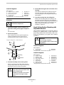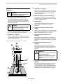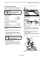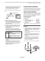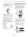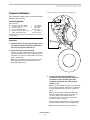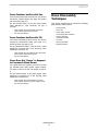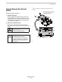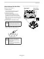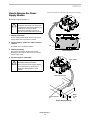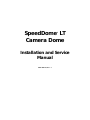
1
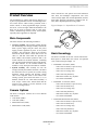
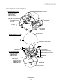
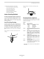
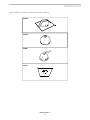
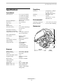
SpeedDome LT
Camera Dome
®
Installation and Service
Manual
8000-1686-01, Rev. A
SpeedDome® LT
Camera Dome
Installation and Service Manual
8000-1686-01, Rev. A
SH 7/97
FCC COMPLIANCE
This equipment has been tested and found to comply with Part 15
of the FCC Rules. Operation is subject to the following two
conditions: 1) this device may not cause harmful interference, and
2) this device must accept any interference received, including
interference that may cause undesired operation.
EQUIPMENT MODIFICATION CAUTION
Equipment changes or modifications not expressly approved by
Sensormatic Electronics Corporation, the party responsible for
FCC compliance, could void the user's authority to operate the
equipment.
WARRANTY DISCLAIMER
Sensormatic Electronics Corporation makes no representation or
warranty with respect to the contents hereof and specifically
disclaims any implied warranties of merchantability or fitness for
any particular purpose. Further, Sensormatic Electronics
Corporation reserves the right to revise this publication and make
changes from time to time in the content hereof without obligation
of Sensormatic Electronics Corporation to notify any person of
such revision or changes.
No part of this manual may be reproduced in any form without
written permission from Sensormatic Electronics Corporation.
SpeedDome is a trademark of Sensormatic Electronics Corporation. Other product names (if any) mentioned herein may be
trademarks or registered trademarks of other companies.
© Copyright Sensormatic Electronics Corporation 1997
ii
TABLE OF CONTENTS
PREFACE....................................................................................................................................................................V
CHAPTER 1 INTRODUCTION ............................................................................................................................ 1-1
PRODUCT OVERVIEW .................................................................................................................................................. 1-2
Main Components .................................................................................................................................................. 1-2
Camera Options...................................................................................................................................................... 1-2
Basic Genealogy..................................................................................................................................................... 1-2
Indoor Mounting Methods ..................................................................................................................................... 1-4
Features .................................................................................................................................................................. 1-6
SPECIFICATIONS .......................................................................................................................................................... 1-9
CHAPTER 2 INSTALLATION.............................................................................................................................. 2-1
BEFORE YOU BEGIN ................................................................................................................................................... 2-2
Safety ..................................................................................................................................................................... 2-2
Verifying and Unpacking ....................................................................................................................................... 2-2
Tools and Equipment Required.............................................................................................................................. 2-2
Parts Check ............................................................................................................................................................ 2-2
INSTALLATION PROCEDURE ........................................................................................................................................ 2-2
How to Use this Section ......................................................................................................................................... 2-2
Hard/Tile Ceiling Mounting................................................................................................................................... 2-2
Pendant Mount Installation .................................................................................................................................... 2-6
Chassis Installation................................................................................................................................................. 2-8
Bubble and Skirt Installation................................................................................................................................ 2-10
CHAPTER 3 SERVICE .......................................................................................................................................... 3-1
BEFORE YOU BEGIN ............................................................................................................................................. 3-2
Tools and Equipment Required.............................................................................................................................. 3-2
TROUBLESHOOTING .................................................................................................................................................... 3-2
DOME DISASSEMBLY TECHNIQUES ............................................................................................................................. 3-5
How to Remove the Unicard Board ....................................................................................................................... 3-6
How to Remove the Pan Motor.............................................................................................................................. 3-7
How to Remove the Power Supply Module ........................................................................................................... 3-8
How to Remove the Clock-Spring Cable Assembly............................................................................................... 3-9
How to Remove the Camera Assembly................................................................................................................ 3-10
How to Remove the Camera/Lens Board ............................................................................................................. 3-11
How to Remove the Tilt Motor ............................................................................................................................ 3-12
How to Remove the Slip-Ring Assembly............................................................................................................. 3-13
How to Remove the Eyeball Assembly ................................................................................................................ 3-14
DOME MAINTENANCE ............................................................................................................................................... 3-15
Setting Communications Jumpers ........................................................................................................................ 3-15
Setting the Dome Address.................................................................................................................................... 3-15
iii
Preface
Who should use this manual
Customer Engineers and Dealers who want to install and service
the camera dome.
How this manual is organized
This manual contains the following three chapters:
1
INTRODUCTION provides a product overview and specifications.
2
“INDOOR” INSTALLATION provides procedures required to
mount the dome indoors.
3
SERVICE provides
information.
troubleshooting
and
maintenance
Related Documents
Installation and service of this camera dome does not require
detailed knowledge of how it works or its circuits. However, if this
information is required, order the following document.
Theory for SpeedDome LT Camera Domes, document number
8000-1692-01.
Questions?
For technical support or questions that this manual does not
address:
Customer Engineers call: 1-800-543-9740
Dealers call: 1-800-442-2225
v
CHAPTER
SpeedDome LT
CHAPTER 1
INTRODUCTION
ν
Product Overview .....................................................................1-2
Describes how the dome works, its mounting methods,
major components, and features.
ν
Specifications ............................................................................1-9
Lists electrical, environmental, regulatory, and
mechanical specifications for the dome.
SPEEDDOME LT
1-1
1
INTRODUCTION
Product Overview
The SpeedDome LT camera dome (Figure Chapter 1-1)
is part of a programmable network of camouflaged cameras. These devices enable security personnel, from a
remote console, to track programmed targets (presets),
near or far, even in low light. Small and unobtrusive, the
dome can be used in facilities such as retail stores,
casinos, manufacturing facilities, hotels, and hospitals,
especially where appearance is important.
These cameras have 12X optical zoom with continuous
auto focus and backlight compensation. The color
camera is fully digital, has no field adjustments, and has
better light sensitivity and picture resolution (430 TV
lines) due to Digital Signal Processing (DSP).
Figure Chapter 1-1. SpeedDome LT chassis
Carriage
Assembly
Main Components
The dome consists of the following assemblies:
• Carriage assembly. This assembly mounts directly
into the housing. The carriage assembly contains the
dome’s power supply and pan motor; the power
supply provides regulated dc power to the eyeball
assembly. The Unicard PC board is the interface
between the dome and the console and receives all
video, ac, and data. This board also provides the
dome address and transient protection and is the
central controller for all dome functions, controlling
360° pan movement and storing targets and patterns.
An LED indicator on the Unicard enables the
installer to verify when power and data are available.
• Eyeball assembly. This assembly fits into the
carriage assembly and contains the dome’s tilt motor
and electronics used to operate the eyeball, storing
automatic camera patterns and directing camera
video to the composite cable via the Unicard. The
rotating eyeball, gloss black and 190cm (7.5”) in
diameter, houses the 1/4” CCD camera assembly. A
clear, acrylic “contact lens” mounts flush with the
contour of the eyeball to prevent detection of the
camera’s viewing position.
Camera Options
The dome, as shipped, contains one of four different
CCD cameras.
• Color NTSC (60Hz)
• Color PAL (50Hz)
• Monochrome EIA (60Hz)
• Monochrome CCIR (50Hz)
Eyeball
Assembly
Basic Genealogy
The dome is available in the four versions listed below.
Basic parts are listed under each version. An exploded
view is shown in Figure Chapter 1-2.
• RAS588LP Color NTSC (60Hz)
− 0100-1326-01 Chassis, Top-Level Assy.
− 0300-1742-01 Chassis Assy.
− 0300-1743-01 Carriage Assy.
− 0300-1740-01 Eyeball Assy.
− 0400-0507-01 Skirt Assy. Eyeball
− 0351-0558-01 Install Kit
• RAS588LP-1 Color PAL (50Hz)
− 0100-1326-02 Chassis, Top-Level Assy.
− 0300-1742-02 Chassis Assy.
− 0300-1743-01 Carriage Assy.
− 0300-1740-02 Eyeball Assy.
− 0400-0507-01 Skirt Assy. Eyeball
− 0351-0558-01 Install Kit
• RAS587LP Monochrome EIA (60Hz)
− 0100-1326-03 Chassis, Top-Level Assy.
− 0300-1742-03 Chassis Assy.
− 0300-1743-01 Carriage Assy.
− 0300-1740-03 Eyeball Assy.
− 0400-0507-01 Skirt Assy. Eyeball
− 0351-0558-01 Install Kit
SPEEDDOME LT
1-2
INTRODUCTION
Figure Chapter 1-2. Chassis components
Pan Motor (not shown)
3501-0009-01
0300-1742-00 Chassis, Indoor
-01 Color NTSC camera
-02 Color PAL camera
-03 BW EIA camera
-04 BW CCIR camera
0300-1743-01 Carriage Assy.
Power Supply
5606-0002-02
Unicard Board (hidden)
0301-0518-03
Pan Gear
0500-3869-01
Yoke Bracket
0500-3844-01
Camera Shroud
0500-3795-01
0400-0507-01 Skirt Assy., Eyeball
Camera/Lens Board (hidden)
0301-0832-01
Sector Gear
0500-3817-01
Camera Cable,
integral to camera assy.
0300-1740-00 Eyeball Assy.
-01 Color NTSC camera
-02 Color PAL camera
-03 BW EIA camera
-04 BW CCIR camera
Cable Assy., Slip Ring Interface
0650-0623-01
Spool Cable Retainer
0500-3841-01
Camera/Bracket Assy.
0300-1754-00
-01 Color NTSC camera
-02 Color PAL camera
-03 BW EIA camera
-04 BW CCIR camera
Tilt Motor
3501-0010-01
Acrylic Lens
0500-4131-01
Lens Shroud
0500-3796-01
SPEEDDOME LT
1-3
INTRODUCTION
• RAS587LP-1 Monochrome CCIR (50Hz)
− 0100-1326-04 Chassis, Top-Level Assy.
− 0300-1742-04 Chassis Assy.
− 0300-1743-01 Carriage Assy.
− 0300-1740-04 Eyeball Assy.
− 0400-0507-01 Skirt Assy. Eyeball
− 0351-0558-01 Install Kit
Figure Chapter 1-4. Surface mounting to tile
ceilings
Indoor Mounting Methods
The dome’s housing mounts directly to indoor hard or
tile ceilings using hardware supplied with the dome or
to one of several optional mounting structures. These
methods facilitate quick installation after site preparation, enabling wiring to be done during rough
building construction.
Hard/Tile Ceiling Mounting
The dome’s housing can be surface mounted directly to
sheet rock ceilings, wood ceilings, or ceilings with special finishes (Figure Chapter 1-3). The housing can also
be mounted in a section of tile ceiling using a ceiling Tbar among other components (Figure Chapter 1-4).
Mounting hardware varies with the type of installation
kit.
Figure Chapter 1-3. Surface mounting to hard
ceilings
Side View
Mounting Structures (Optional)
The dome’s chassis can be mounted to several indoor
ceiling mounting structures (Figure Chapter 1-5). These
structures are as follows:
Product
Code
Mounting Structure
RH105-8
Bubbles. The following bubbles are available:
RU105
RU106
RU107
RU108
Clear bubble
Silver bubble
Smoked bubble
Gold bubble
RHI2X2*
Drop ceiling 2x2 mount. Allows chassis to be
recessed into dome housing that fits a 2x2
opening.
RHICM*
Hard ceiling mount with adjustable ceiling
kit. For sheet rock, wood, or ceilings with
special finishes, a hard ceiling housing is
available. The 20mm lip of this housing
enhances the appearance of the dome in well
designed ceilings.
RHIPM*
Pendant mount with I-beam clamp. For direct
installation to hard ceilings, an I-beam, or other
support structure. A section of 38mm pipe is
added to the hard ceiling housing to form a
pendant mount.
RH400*
2x2 plenum dome shroud. Covers electrical
cables within plenum.
RH530*
T-bar molding kit. Permits installing a dome to
a hard ceiling using hardware that a “Drop
Ceiling 2x2 Mount” mounts to.
* These options come in white but can be easily painted to
match decor.
SPEEDDOME LT
1-4
INTRODUCTION
Figure Chapter 1-5. Indoor mounting structures (optional)
RHI2X2
RHICM
RHIPM
RH530
SPEEDDOME LT
1-5
INTRODUCTION
Features
Performance Features
In alphabetical order:
• Apple Peel Default Pattern. Controller dependent,
the dome automatically defaults to an “apple peel”
pattern where, starting at the ceiling, the camera pans
the entire viewing area three times, dropping 30°
after each pan.
• Automatic Calibration. When power is first
applied, the dome calibrates its position-sensing
electronics by going through a one-minute motion
routine (during which it ignores commands). Once
calibrated, the dome is in its "home" position, ready
for use, with the lens pointing at wide angle along
the top of the ceiling. "Homing" does not occur
again unless power is removed.
• Automatic Lens Control (ALC). Also called autoiris, this feature enables the lens iris to adjust to
different lighting conditions automatically; however,
manual adjustments can be made at the console. See
Iris Preference in this section.
• Automatic/Manual Dome Reset. A watchdog
circuit automatically resets the dome if voltage levels
or preprogrammed instructions are incorrect. The
dome can be manually reset using keyboard
commands from the console.
• Auto-Pan. The dome can be taught to continuously
pan any designated area. Once activated, the pattern
repeats until interrupted.
• Automatic Synchronization. The dome automatically synchronizes to a 50- or 60Hz ac source or
free-runs on its own internally generated clock.
• Continuous Rotation. The dome rotates 360°.
There are no end stops.
• DSP Motor Control. Digital signal processing
(DSP) and dynamic motor braking assure precise
and fluid camera movement and accuracy.
• Focus Preference™. Provides automatic focusing
with the benefits of manual override.
• High Resolution Cameras. The dome uses monochrome and color cameras. These cameras have 12X
optical zoom with continuous auto focus and
backlight compensation.
• Iris Preference. Manual or automatic iris control
enables the operator, on a selective basis, to
manually fine-tune back lighting problems for proper
illumination of the subject.
• QuickView™. The dome can precisely pan, tilt,
zoom and focus in less than two seconds. This speed
and accuracy enables one SpeedDome LT to offer
better coverage than multiple fixed cameras.
• Switching Power Supply. This circuit reduces
power consumption and enables cable runs of up to
120 meters (394’).
• Transient Protection. All dome inputs and outputs
are opto-coupled, transformer isolated, or provided
with heavy duty transient protection to enhance longterm product reliability.
• Zoom Adjusted Program (ZAP)™. This feature
automatically adjusts pan and tilt speeds during
manual operation to keep the video image constant
as the camera lens adjusts from wide angle to
telescopic. For example, a 12x lens panning at
100°/second at full telephoto slows to 0.5°/second at
full zoom.
• 180° Flip. The dome can follow a target as it moves
toward the camera, directly beneath it, and away
from the camera by flipping its camera 180° at the
point where the target passes directly beneath the
dome.
• 12x “Fast” Lens. A 4-48mm, f1.6 lens enables the
video image to fill the monitor screen at 15m (50’).
SPEEDDOME LT
1-6
INTRODUCTION
Video System Dependent Features
VM16 System
Certain dome features depend on the video system the
dome is used with:
• Sensormatic Video Manager system with RS422
• Sensormatic VM8, VM16, or VM96 systems
• American Dynamics AD083-02A system.
Following are features associated with each type of
system.
• Proportional pan and tilt speed control scaled to
zoom position
• Four programmable targets
• Apple Peel pattern
• Flip function
• Loadable program code
• Console V-phase adjustment
• Address range from 1 to 16
• Auto pan.
Video Manager System with RS422
• Pan and tilt speeds of 0.5° to 24° per second scaled
to zoom position
• User selectable pan speed multipliers: X1, X2, X3,
X4
• Four programmable targets
• Console V-phase adjustment
• Flip function
• Address range from 1 to 58.
VM8 System
• Proportional pan and tilt speed control scaled to
zoom position
• Pan lock, Apple peel, and flip function keys
• Loadable program code
• Console V-phase adjustment
• Flip function
• Address range from 1 to 8.
VM96 System
• Proportional pan and tilt speed control scaled to
zoom position
• Unlimited programmable Quick Views
• Apple Peel pattern
• Loadable program code
• Automatic V-phase adjustment initiated by operator
• Flip function
• Address range from 1 to 96
• Auto pan.
AD2083-02A System
• Proportional pan and tilt speed control, eight speeds
scaled to zoom position
• Sixteen programmable targets (presets)
• Apple Peel pattern
• Console V-phase adjustment
• Flip function
• Address range from 1 to 99
• Auto pan.
SPEEDDOME LT
1-7
INTRODUCTION
Installation & Service Features
In alphabetical order:
• Daisy-chaining. Control cables can be daisychained from dome to dome (10 domes maximum
for RS422), using up to 914m (3000’) of cable.
(RS422 uses two, 22 AWG, individually shielded,
twisted pairs; SensorNet uses one 22 AWG twisted
pair without a shield.)
• Safety. The camera dome meets all international
regulatory agency standards. Electrically, the dome
uses low-voltage Class 2 circuitry, and cable
connectors keyed to eliminate electrical hazards
during use. Indoor domes use safety chains to anchor
the dome to building structural members and a safety
lanyard to retain the chassis in its housing during
servicing.
• Interchangeability. Each dome can be easily moved
to a new location.
• Snap-Hinge Chassis. Two sets of spring-loaded
locking pins enable the light-weight, camera chassis
to swing out of its housing for servicing or removal.
• Internationally-recognized connectors. Composite and video cables from the controller connect to
the dome via internationally recognized screwterminal connectors. The dome address can be
changed without cable disconnect (powering down
the dome).
• Simple Disassembly. Only a Phillips screwdriver is
required to disassemble each motor (2 screws), the
slip ring (2 screws), the camera /bracket assembly (2
screws), and each pc board (3 to 4 screws). The
dome can be located up to 250m (820’) from the
junction box.
• Line lock. The dome can free-run on its own
internally-generated 2.5MHz signal, or to prevent
picture rolling on the monitor, be sync’d to a 50 and
60Hz ac source.
• V-Phase Adjustment. The dome has a remote Vphase adjustment that enables synchronization to any
line phase by one person at the control console.
• Power and communications LEDs. On the dome’s
Unicard, green power and yellow communications
LEDs (same as on the J-Box) indicate that power
and data are reaching the dome.
• Remote manual dome reset. The dome can be
manually reset using keyboard commands from the
console.
SPEEDDOME LT
1-8
INTRODUCTION
Regulatory
Specifications
Operational
Pan/Tilt Speed........................ 2° to 18° per second for
12-120mm focal length
3° to 24° per second for
8-180mm focal length
(based on zoom position)
Pan Speed Multiplier ............. 2X, 3X, 4X
Pan Travel.............................. 360° continuous
Tilt Travel.............................. >90°
Zoom
Optical Zoom ......................... 12X
Pan/Tilt Accuracy .................. ±0.5° (allows targeting up
to 12X zoom)
Zoom/Focus Accuracy ........... ±0.5%
Camouflage Lens Density ...... Clear
Target (Preset) Access Time.. <2 second to position at
60% of zoom setting
Auto Synchronization
Line Locked ........................... Remote V-phase
adjustment
Internal................................... Built-in sync generator
Video Output Connector ........ Female BNC
Address Range ....................... 1-99
Targets (Presets) .................... 4 with VMRS422
4 with VM16
7 with POS/EM
16 with AD2083-02A
Unlimited with VM96
Emissions............................... 47CFR Part 15, Subpart
B, Class A (FCC)
EN55022 Class B (CE)
Immunity................................ EN50082-1 (CE)
Safety..................................... UL2044
CSA 22.2 No. 1 (cUL)
EN60950 (CE)
Environmental
Operating Temperature.......... –10° to 50°C (14°–122°F)
Relative Humidity.................. 0 to 95% non-condensing
Mechanical
Electrical
Primary Source ...................... 18 to 30Vac, 50/60 Hz
Design Tolerance ................... 16 to 36Vac, 50/60 Hz
Current ................................... 0.85A max.
Power On In-Rush Current .... 1.5 A
Program Storage .................... 256 Kbytes of Flash
memory
Data Storage .......................... 96 Kbytes of SRAM
Surge Protection
Video Output ......................... 100A
Power Line............................. 60V, 1.5 joules, 250A
RS422 Comm. Line ............... 5.6V, 0.1 joules, 40A
RS485 Comm. Line
Isolated transformer
coupled, .10kA impulse
rated gas tube
SPEEDDOME LT
1-9
27.3 cm
(10.8 in.)
28.1 cm
(11.06 in.)
3.35 kg
(7.4 lbs)
INTRODUCTION
Camera
Field-of-View Formulas:
Monochrome/Color
Horizontal view = (3.2 x a)/b
Type................................ Interline transfer
1/4” CCD array
Scanning Area................. 3.2 (H) x2.4 (V) min.
Scanning System............. 2:1 interlace
Video Out ....................... 1.0Vp-p/75 ohm composite
Signal-to-Noise ............... 48dB (typical)
Vertical view = (2.4 x a)/b
where a = distance from camera in meters or feet
where b = focal length (mm)
Example of a wide angle view with the lens at 4mm at
10m (30.5’) from the camera:
(3.2mm x 10m)/4mm = 8m (24.4’) horizontal view
(2.4mm x 10)/4mm = 6m (18.3’) vertical view
Monochrome only
Horizontal Resolution ..... 380 lines at center
Minimum Illumination .... 0.1 lux (AGC on) at f1.6
AGC................................ >24dB
EIA
Pickup Device................. 510 (H) x 492 (V) pixels
Scanning ......................... 525 lines, 60 fields, 30 frames
Horizontal ....................... 15.734 kHz
Vertical ........................... 59.9 Hz internal sync
CCIR
Pickup Device................. 510 (H) x 582 (V) pixels
Scanning ......................... 625 lines, 50 fields, 25 frames
Horizontal ....................... 15.625kHz
Vertical ........................... 50Hz
Color only
Horizontal Resolution ..... >450 lines at center
Minimum Illumination .... 2.25 lux (AGC on) at f1.6
White Balance................. Through-the-Lens (TTL) Auto
Tracing White balance (ATW)
NTSC
Pickup Device................. 768 (H) x 494 (V) pixels
Scanning ......................... 525 lines, 60 fields, 30 frames
Horizontal ....................... 15.734kHz
Vertical ........................... 59.9 Hz internal sync
PAL
Pickup Device................. 752 (H) x 582 (V) pixels
Scanning ......................... 625 lines, 50 fields, 25 frames
Horizontal ....................... 15.625kHz
Vertical ........................... 50Hz
Lens
Design............................. Aspherical
Focal Length ................... 4 to 48 mm
Aperture .......................... f1.6
Viewing Angle*
4 mm ............................... 47.0°(H) x 35.2°(V)
48 mm ............................. 4.0°(H) x 3.0°(V)
*Equivalent to 8mm to 80mm on 1/2 in. CCD array.
SPEEDDOME LT
1-10
CHAPTER
“Indoor” SpeedDome LT
CHAPTER 2
INSTALLATION
In this chapter:
ν
Before You Begin ......................................................................2-2
Things you need to do before you install the camera dome.
ν
Installation Procedure ..............................................................2-2
Shows you how to mount the dome indoors to either a
hard ceiling, tile ceiling, I-beam, pendant mount, or
existing SpeedDome housing.
SPEEDDOME LT
2-1
2
INDOOR INSTALLATION
• Installation kit, 0351-0558-01.
Before You Begin
Safety
Installation Procedure
ALWAYS USE:
This section explains how to install the camera
dome indoors.
• Proper safety equipment for the location and type of
installation.
• Proper lift equipment to reach the installation.
• Safety features of the lift equipment.
BE SURE:
• Electrical power is not connected to the dome during
installation.
• Electrical power is not connected to nearby fixtures
that you might touch during installation.
!
WARNING!
Do not install this product in hazardous
areas where highly combustible or
explosive products are stored or used.
Both dome PC boards have electrostatic sensitive
devices, use caution when handling the dome.
CAUTION—ELECTROSTATIC SENSITIVE
DEVICE!
Use a grounding strap when handling the
PC board.
How to Use this Section
1. Mount the housing to the ceiling. Next, insert the
dome’s chassis into the housing (one of four
indoor mounting structures):
Hard/tile ceiling mounting ..................................... 2-2
Indoor Mounting Structures:
Verifying and Unpacking
• Verify that all parts have arrived and their
configuration is correct.
• Lay out parts in the order you will need them. Do not
clutter the area or create a trip hazard.
Tools and Equipment Required
You should have on hand the following equipment:
• Phillips-head screwdriver
• 0.4 x 2.5mm slotted screwdriver (for wire
connections)
• Power drill with 1/8”, 1/4”, and 3/8” drill bits
• Hammer
• Socket wrench with 5-inch extension, and 5.5mm,
10mm, and 11mm sockets
• 18-14 AWG and 22-20 AWG wire strippers
• Hand vacuum and broom.
Parts Check
Other than these instructions, in the shipping box
for the dome are the following parts:
Hard ceiling surface mounting
with adjustable bracket ......................................... 2-3
2x2 tile mount installation ..................................... 2-5
Pendant mount installation ................................... 2-6
Pendant (I-beam) mounting.................................. 2-7
2. Set up the dome and attach it to its housing:
Dome chassis setup and
attachment............................................................ 2-8
3. If used, you can attach an optional skirt and
bubble to the SpeedDome chassis:
Skirt and bubble attachment............................... 2-10
Hard/Tile Ceiling Mounting
The following methods show you how to mount the
dome’s housing directly to the surface of a hard
ceiling (sheet rock or wood beams) or to the T-bar
intersections of a tile ceiling.
Hard Ceiling Surface Mounting
This procedure explains how to mount the dome’s
housing to a support beam or other attachment
point using safety chain. After completing this
procedure, go to “Chassis Installation,” page 2-8.
• Chassis, top-level assembly, 0100-1326-00
• Chassis assembly, 0300-1742-00
• Eyeball assembly, 0300-1740-00
SPEEDDOME LT
2-2
INDOOR INSTALLATION
Install Kit Supplied
4. Feed cables through a hole in the side of the
housing.
0351-0393-01*
a) Washer, FL, #10 x .040THK
2
b) Eyebolt, 10-24 x 1-3/4”L
1
c) Nut, Lock, ZN, 10-24
1
d) “S” Hook, open
2
e) Chain, sash
6FT
* Only parts used in this procedure are listed.
2848-8100-17
2882-0112
2838-9154-05
2897-0004
2898-0002
5. Insert the housing into the ceiling hole.
Procedure
!
Feed video and multiconductor cables through one
of the two holes in the side of the housing. Then
cover all openings in the housing with the aluminum
tape supplied.
Shipping box contains a template—do
not throw the template out.
1. Using the template, scribe a 35.6cm (14”)*
hole in the ceiling or tile (Figure Chapter 21).
Cut out the hole.
2. Secure the eyebolt.
Place a washer (a) over the eyebolt supplied (b).
Insert the eyebolt into a hole in the top of the
housing and secure using a washer and nut (c).
With the three mounting tabs of the housing in the
up position, insert the housing into the ceiling hole,
then from inside the housing bring the tabs down and
tighten their screws to secure. The housing is now
ready for chassis installation (go to “Chassis
Installation,” page 2-8).
Hard Ceiling Surface Mounting with
Adjustable Bracket
This procedure explains how to mount
housing to a support beam or other
point using safety chain and bracket.
pleting this procedure, go to page 2-8
installation.
!
Figure Chapter 2-1. Hard mount
the dome’s
attachment
After comfor chassis
WARNING!
For all ceilings except tile.
Ceilings MUST be able to hold at least
9kg (20 lbs)!
e
d
Install Kit Supplied
Cables
0351-0393-01*
b
i)
“S” hook, open
2
2897-0004
j)
Chain, sash
6 FT 2898-0002
* Only parts used in this procedure are listed.
a
Install Kit Supplied
0351-0394-01*
Mounting
tabs
c
Cable Access
Hole
3. Connect the safety chain to the eyebolt.
Using an S-hook (d), hang safety chain (e) from a
strong ceiling member and, using a second S-hook,
attach other end of the chain to the eyebolt.
!
a) Support, Z-shape
2
b) Support, L-shape
2
c) Nut, wing 10-32
8
d) Screw, mach., M6x12
4
e) Adapter plate
1
f)
Spacer, Nylon
16
g) Washer, flat #10
8
h) Nut, wing 10-32
8
* Only parts used in this procedure are listed.
WARNING!
Keep chain as taut as possible! Close
ends of each S-hook!
DO NOT use sprinkler or fire control
system when securing the safety
chain!
SPEEDDOME LT
2-3
0500-3440-01
0500-3439-01
2834-0007-01
5801-4074-311
0500-3982-01
3110-0016
2848-6301-23
2834-0007-01
INDOOR INSTALLATION
3. Install the “L” supports.
Procedure
!
WARNING!
Shipping box contains a template—do
not throw the template out.
1. Tile ceilings only (Figure Chapter 2-2).
Remove the ceiling tile(s) and inspect the ceiling
frame. The frame must be capable of withstanding
9kg (20 lbs) of weight and the forces generated as
the dome pans and tilts.
!
WARNING!
If ceiling frame cannot support dome,
ask building maintenance to install
additional ceiling supports.
All ceilings. Using the template, scribe a 35.6cm
(14”) hole in the ceiling or tile. Cut out the hole.
2. Install the “Z” supports.
Place “Z” supports (a) on the ceiling’s top surface.
For tile ceilings: Make sure the edge of the supports
rests flush with edges of tile.
Figure Chapter 2-2. Installing "Z" support
i
From inside the housing, insert the four screws (d)
provided through the holes in the top of the housing
and into the adapter plate (e).
5. Install spacers.
Place enough spacers (f) over each stud in the
adapter plate to compensate for the ceiling
thickness.
6. Install the housing into the hole in the
ceiling.
With its three mounting tabs in the up position, insert
the housing into the ceiling hole until the studs in the
plate fit through the slots in the “L” supports.
7. Secure the adapter plate to the “L”
supports.
Bring the three mounting tabs of the housing down
and tighten their screws to secure. Then secure the
plate to the “L” supports using washers (g) and wing
nuts (h).
Using an S-hook (i), hang safety chain (j) from a
strong ceiling member and, using a second S-hook,
connect the other end of the chain to one of the “L”
supports.
h
j
4. Attach the adapter plate to the housing.
8. Connect the safety chain to the “L”
supports.
c
S
Place the two “L” supports (b)—cut to length, if necessary—over the threaded studs of the “Z” supports
and fasten together using four washers and four
wing nuts provided (c).
g
S
!
b
a
f
WARNING!
Keep chain as taut as possible! Close
ends of each S-hook!
DO NOT use sprinkler or fire control
system when securing the safety
chain!
Cables
Mounting
tabs
e
9. Feed cables through a hole in the side of the
housing.
Feed video and multiconductor cables through one
of the two holes in the side of the housing. Then
cover all openings in the housing with the aluminum
tape supplied. The housing is now ready for chassis
installation (go to “Chassis Installation,” page 2-8).
d
SPEEDDOME LT
2-4
INDOOR INSTALLATION
2x2 Tile Mount Installation
Figure Chapter 2-3. Installing "Z" support
This procedure explains how to mount the dome’s
housing in ceiling tile. After completing this
procedure, go to page 2-8 for chassis installation.
!
61cm (24")
WARNING!
If ceiling frame cannot support dome,
ask building maintenance to install
additional ceiling supports.
a
Install Kit Supplied
0351-0376-01*
a) Bar, ceiling tee
1
0500-0263-01
b) Tab
2
0500-0264-04
c) Clip, T-bar
4
1400-0033-01
d) Chain, sash
6 FT 2898-0002
e) “S” hook, open
2
2897-0004
* Only parts used in this procedure are listed.
Area of Detail
Frame
b
Slot
Extension Bar Install Kit Supplied
0351-0243-01*
A) Bar, extension
4
B) Rivet, pop, .125”x.188”-.250”
16
C) Washer, flat #5
16
* Only parts used in this procedure are listed.
3. Secure the T-bar.
Procedure
1. Inspect the ceiling frame (Figure Chapter 23).
Remove the ceiling tile(s) and inspect the ceiling
frame. The frame must be capable of withstanding
9kg (20 lbs)* of weight and the forces generated as
the dome pans and tilts.
!
Bend tab
forward
Bend tab
outward
0500-3326-01
2873-0004-05
2848-1408-01
WARNING!
If ceiling frame cannot support dome,
ask building maintenance to install
additional ceiling supports.
Slide the tab through the slot in the existing frame
61cm (24”) from the T-bar opposite. Bend the ends
of the tab outward to secure. Repeat for the other
end of the bar.
4. Set the housing into the ceiling opening
(Figure Chapter 2-4).
Set the housing into the ceiling opening. If installing
in a 2x2 ceiling, remove an adjacent ceiling tile to aid
installation.
Figure Chapter 2-4. Installing the dome housing
Ceiling
member
e
d
2. Placement of the T-bar.
Housing
c
Cut the 2x4 ceiling tile to 60.3cm (23.75”) using the
length of the T-bar supplied (a) as a guide. Then
attach this T-bar (see detail) by centering steel tab
(b) through the slot at end of the T-bar. Bend the tab
as shown.
e
Eyelet
Cables
For slightly larger openings, see text and Figure
Chapter 2-5.
SPEEDDOME LT
2-5
INDOOR INSTALLATION
Extension bars (A) mount to the edge of the housing
to provide proper fit. Buttjoint as many bars as
required using pop rivets (B) and washers (C), four
per bar, as shown below. Do not use clips.
Figure Chapter 2-5. Installation using extension
bars
C
Edge of housing
Pendant Mount Installation
The following methods show you how to mount the
dome’s base directly to the surface of a hard ceiling
(sheet rock) or I-beam using a pipe as a pendant.
Standard Pendant Mounting
This procedure explains how to mount the dome’s
housing to a section of pipe extending downward
from the ceiling. After completing this procedure,
go to page 2-8 for chassis installation.
A
Install Kit Supplied
B
0351-0392-01*
5. Secure the housing to the T-bar.
Clamp the housing to the T-bars by snapping a T-bar
clip (c) over the raised edge of the housing and the
T-bar. Center this clip along the edge. Repeat for
each side of housing.
6. Connect one end of the safety chain to the
housing, with opposite end secured to a
ceiling member.
Wrap safety chain (d) around a strong ceiling
member while attaching it to itself using an S-hook
(e). Using a second S-hook (e), attach the other end
of the chain to one of two eyelets on the housing.
!
a) Flange, 1-1/4” dia.
b) Anchor bolt, 1/4”x2-1/4” w/hdwr
c) Pipe, 1-1/4”, straight, 6m max.†
d) Nipple, short 1-1/4”x2”
e) Fitting, pipe tee, 1-1/4”
f)
Cap pendant
* Only parts used in this procedure are
ends.
1
1400-0069-01
4
2880-0011
1
CE supplied
1
1417-0041-01
1
1417-0040-01
1
0500-3964-01
listed. †threaded both
Procedure
1. Using the flange (a) as a template, mark hole
locations on ceiling for four bolts (Figure
Chapter 2-6).
Remove the flange and drill four .64cm (1/4”) holes
to required depth.
WARNING!
Keep chain as taut as possible! Close
ends of each S-hook!
DO NOT use sprinkler or fire control
system when securing the safety
chain!
7. Feed cables through a hole in the side of the
housing.
Feed video and multiconductor cables through one
of the two holes in the side of the housing and
reinstall the adjacent ceiling tile. The housing is now
ready for chassis installation (go to “Chassis
Installation,” page 2-8).
For each hole, screw two nuts onto the anchor bolt
provided, with two threads of the second nut
extending over end of bolt (b) to prevent damage to
bolt threads.
Hammer the bolt into the ceiling leaving only its
threads exposed. Remove the nuts and bolt the
flange to the ceiling using the flat washers, lock
washers and nuts supplied.
Figure Chapter 2-6. Pendant mounting flange
a
b
Washers
Nut
SPEEDDOME LT
2-6
INDOOR INSTALLATION
2. Connect the nipple to the pipe by using the
pipe tee (Figure Chapter 2-7).
Thread the straight pipe (c) (not supplied) and nipple
(d) into the pipe tee (e). Thread the nipple of the
entire assembly into the flange.
Figure Chapter 2-7. Pendant mount - exploded
view
Flange
Procedure
1. I-beam attachment (Figure Chapter 2-8).
Set the base plate (a) against a suitable ceiling
member. Secure the plate using clamps (b) and
hardware supplied (c-f)—see base plate hole-to-hole
dimensions, below. Attach the flange (g) using
hardware supplied.
d
Cables
e
Figure Chapter 2-8. I-beam mountCeiling
member
20M
(20’)
b
c
f
a
c-f
Housing
3. Feed cables through a hole in the side of the
housing.
Base plate holeto-hole
dimensions
g
Hardware
supplied
90mm
(3.5")
Feed video and multiconductor cables through
center hole of pipe tee and down through the pipe.
128mm (5")
Note: Remove the Cinch-Jones connector, if used,
to enter pipe.
179mm (7")
230mm (9")
Slip the cap (f) onto the pipe, then thread housing
onto the pipe. The housing is now ready for chassis
installation (go to “Chassis Installation,” page 2-8).
Pendant (I-Beam) Mounting
This procedure explains how to mount the dome’s
housing to an I-beam in the ceiling. After completing this procedure, go to page 2-8 for chassis
installation.
Install Kit Supplied
0351-0391-01*
a)
b)
c)
d)
e)
f)
g)
h)
i)
Base plate
Clamp plate
Screw, mach. M6x70
Washer, flat
Washer, SL, M6
Nut, hex, M6
Flange, 1-1/4” dia.
Nipple, short 1-1/4”x2”L
Fitting, pipe tee, 1-1/4”
1
2
4
12
8
8
1
1
1
0500-3975-01
0500-3976-01
5801-4194-311
5840-0500-020
5846-0500-020
5820-0500-020
1400-0069-01
1417-0041-01
1417-0040-01
2. Vertical/horizontal mounting (Figure Chapter
2-9).
Thread nipple (h) and purchased part into the pipe
tee (i) and screw the entire assembly into the base.
Next, feed video and multiconductor cables through
center hole of pipe tee.
Note: Remove the Cinch-Jones connector, if used,
to enter pipe.
Finally, thread the housing onto the pipe. The
housing is now ready for chassis installation (go to
“Chassis Installation,” on the next page).
Figure Chapter 2-9. Vertical and horizontal
mountings
Base
h
i
* Only parts used in this procedure are listed.
Purchased
Part
Cables
Pipe
Housing
SPEEDDOME LT
2-7
Note: If replacing pipe tee with
pipe, cable exiting pipe tee must
be no farther than 15.2cm (6”)
from I-beam clamp.
INDOOR INSTALLATION
Chassis Installation
Figure Chapter 2-10. Chassis installation
This procedure explains how to mount the chassis
within the dome housing.
d
c
b
Install Kit Supplied
0351-0558-01*
a)
b)
c)
d)
e)
f)
Connector, BNC, Plug, RG59
Connector, BNC, Jack, RG59
Cable Tie, Nylon, 4”
Tubing, Heat Shrink, Black
Resistor, 180-ohms, ±5%, .25W
Tubing, Heat Shrink, Black
1
1
3
.8ft
2
.5ft
e
2111-0035-01
2111-0034-01
6009-0006
3121-0007
4711-1800-700
3121-0027-01
g
f
* Alphabetical parts listing does not correspond to parts used in
this procedure.
Procedure
h
1. Snap the ball (a) of the lanyard hanging from
the chassis into the bracket (b) at the top of
the housing (Figure Chapter 2-10).
a
2. Place the chassis in the housing.
Squeeze the spring-loaded ejector pins (c) together
to seat the chassis in the corner receptacles (d). The
PC board must face the cables exiting the access
holes in the housing.
Note: After the chassis is in place, remove the foam
packing that prevents the eyeball assembly from
pivoting during shipment.
3. If using a patch cable (0650-0657-01),
connect the cable ends to their respective
receptacles on the Unicard and on the
composite cable from the J-Box (Figure
Chapter 2-11).
Note: If you must replace the Cinch-Jones connector
on the existing composite cable from the J-Box with
a female compression-type connector, continue to
step 4.
Note: If using customer-supplied 22 AWG cable,
wire the receptacle style, compression-type, P3
connector, which comes with the dome, in
accordance with the “Connector Pin Out” table
(column P1) on the next page.
With the chassis hanging down, connect the video
and multiconductor cables to their receptacles (e).
Note: Do not use the alarm input connector (f).
SPEEDDOME LT
2-8
INDOOR INSTALLATION
To Cinch-Jones
connector on composite
To Unicard
terminal block,
P3
To video cable
BNC connector
To Unicard BNC
connector, J1
4. If it is necessary to replace the Cinch-Jones
connector on the composite and video
cables, use the male and female BNC and
compression-type connectors supplied with
the SpeedDome Cable Conversion Kit (03510403-01—Figure Chapter 2-12).
Use the following table and figure for data cable pin
out information.
Connector Pin Outs
Cinch-Jones (P2)
Pin No.
Compression (P1)
Wire Color
7
8
3
4
5
2
1
Signal Name
Brown
Yellow
Black
Red
White
Green
Orange
Using address switches (g), set the dome address
(Figure 2-13).
Figure Chapter 2-13. Setting dome address
MSB LSB
1
1
SW2
Board edge
9
1
2
3
4
5
6
7
type connector,
p/n 2109-0254-06
1
1
7
To existing
J-Box
cables
Female BNC connector,
p/n 2111-0034-01
J1
9
Squeeze the ejector pins (h) and swing the chassis
all the way up, while easing the cables up through
the access holes. Release these pins into the
remaining corner receptacles.
Figure Chapter 2-12. Extending composite
cable
Female compressionMale compression-type
connector, p/n 2109-
Video
6. Lock the chassis into the housing.
Pin No.
Data Out (Lo)
Data Out (Hi)
AC
Ground
AC
Data In (Lo)
Data In (Hi)
SW1
0
Figure Chapter 2-11. Patch cable connection
5. Set the dome address (Figure Chapter 2-13).
0
!
WARNING!
Disconnect cable from power source
when performing cable conversions.
7
To Unicard
Male BNC connector,
p/n 2111-0033-01
SPEEDDOME LT
2-9
!
WARNING!
Ejector pins must be fully inserted in
their receptacles.
INDOOR INSTALLATION
Bubble and Skirt Installation
This procedure explains how to mount the optional
bubble assembly and skirt assembly.
Procedure
2. Secure the skirt assembly or optional
bubble assembly to the chassis (Figure
Chapter 2-15).
Insert its T-lanyard into a slot (a) on the chassis until
both ends catch securely.
Figure Chapter 2-15. Securing the lanyard
1. Snap the four pins of the skirt (or bubble)
assembly into the four chassis receptacles
(a) (Figure Chapter 2-14).
Figure Chapter 2-14. Attaching the skirt
a
SPEEDDOME LT
2-10
Power supply
a
CHAPTER
SpeedDome LT Camera Dome
CHAPTER 3
SERVICE
In this chapter:
ν
Before you begin ......................................................................3-2
Explains things you need to do and tools you
need to have on hand before you service the
camera dome.
ν
Troubleshooting........................................................................3-2
Contains procedures to help you isolate and fix a
problem in the housing or the chassis and eyeball
assembly.
ν
Dome Disassembly Techniques ................................................3-5
Explains how to disassemble the dome and
remove major components.
ν
Dome Maintenance.................................................................3-15
Shows you how to set communications jumpers and
change the dome address.
SPEEDDOME LT
3-1
3
SERVICE
BEFORE YOU BEGIN
Troubleshooting
This chapter contains one troubleshooting procedures. Before you perform this procedure, perform
the following steps first:
Use this procedure if:
ο Try the troubleshooting procedure!
Use this procedure to fix the problem if it is in
the indoor chassis.
−
−
−
−
Read CAUTIONS below.
ο If you cannot fix the problem, ship the
indoor chassis (dome) back to the National
Repair Center.
If the troubleshooting procedure does not fix the
problem, then the manufacturer suggests that
you ship the dome to the National Repair Center
for service. To obtain a repair authorization
number, call 1-800-543-9740 (CEs) or 1-800442-2225 (Dealers).
Tools and Equipment Required
To service the dome, you should have on hand the
following equipment:
−
−
−
−
−
The dome does not respond to commands
The dome does not produce video
The quality of the video is poor
The dome has no lens control.
Dome Software (latest version)
Phillips-head screwdriver
0.4 x 2.5mm slotted screwdriver (for wire connections)
Socket wrench with 5” extension and 5.5mm,
6mm, 8mm, and 10mm sockets
14-18 AWG and 20-22 AWG wire strippers
SPEEDDOME LT
3-2
!
WARNING!
DO NOT use this procedure if the
dome functions but does not pan or
tilt.
!
WARNING!
Ship the indoor chassis to the NRC for
service. If you can’t perform routine
troubleshooting, we strongly recommend
you ship the chassis to the National
Repair Center for service.
CAUTION—ELECTROSTATIC
SENSITIVE DEVICES! Use a grounding
strap when handling either the Unicard
board or the Camera/Lens Board.
SERVICE
Procedure
Perform steps in sequence until the problem is
corrected.
4. Check dome address switches (Figure
Chapter 3-2).
Are they set correctly?
−
1. Check the video on the monitor.
No video? Go to step 2.
Is the contrast or color off?
−
YES: Send the dome (indoor chassis) back to the
National Repair Center.
− NO: Go to step 2.
Does the video roll when switching between
monitors?
−
Figure Chapter 3-2. Dome address switches
Unicard board
YES: Use the video controller or switcher to
synchronize the video vertical sync phases of all
domes to the ac line. For specific instructions,
see the installation and service manual for the
controller or switcher.
NO: Go to step 2.
2. Check ac power and video connections at
the J-box.
MSB LSB
1
1
Is 24Vac absent? Is a video signal absent?
0
−
−
YES: Correct problem at J-box.
NO: Go to step 3.
9
3. Verify that the video cable is securely
connected J1 (video jack) on the Unicard
board (Figure Chapter 3-1).
Is the cable disconnected?
−
−
SW2
Board Edge
SW1
9
5. Isolate the problem to the dome.
If another housing is nearby, detach the dome and
reinsert it to the other housing. Does it display video
or respond correctly to commands?
−
YES: Connect the cable.
NO: Go to step 4.
Address
Switches
0
−
−
YES: If the dome still doesn’t respond, then the
problem is likely in the dome. Ship the dome to
the NRC. If you must repair the dome, continue
troubleshooting to identify the task that removes
the faulty component.
NO: Set the correct address. Go to step 5.
−
Figure Chapter 3-1. Video jack on the Unicard
board
Unicard board
J1-Video
SPEEDDOME LT
3-3
YES: Then the problem is likely the cable
connections to the Unicard board. Go to step 6.
NO: Send the dome back to the National Repair
Center.
SERVICE
6. On the Unicard board, observe the green
power LED (Figure Chapter 3-3).
RS422 or SensorNet cable is properly attached
to connector P3. If OK, then replace the Unicard
board.
Is the +12Vdc, green LED off or not on steady?
−
−
P3 Connector (RS422 Data Comm.)
YES: Indicates loss of power to or from power
supply. Verify that the 22Vac (min.) cable is
properly attached to the 7-pin connector, P3
(pins 3, 4 and 5). Ensure all cable connections
within the dome are secure. If O.K., then replace
the Unicard board.
NO: Go to step 7.
3
4
5
Color
Black
Red
White
Color
Designation
7
6
2
1
Orange
Green
Yellow
Brown
RS422 Data In High (+)
RS422 Data In Low (–)
RS422 Data Out High (+)
RS422 Data Out Low (–)
P3 Connector (SensorNet Data Comm.)
P3 Connector (AC In)
Pin
Pin
Designation
Pin
Color
Designation
AC
Ground
AC
1
2
—
—
SensorNe* (–)
SensorNet* (+)
* NOTE: 2-wire, twisted, unshielded, 22AWG cable.
9. Check Unicard board.
Figure Chapter 3-3. LEDs on the Unicard
Does the dome produce video and respond to
commands?
−
YES: Then it is likely that the connectors were
not seated properly.
− NO: Then replace the Unicard board.
If none of these steps worked, then send the dome
back to the NRC. To obtain a repair authorization
number, call 1-800-543-9740 (CEs) or 1-800-4422225 (Dealers).
RED GRN YEL
If you need to identify and replace the faulty
component, continue with the troubleshooting
procedure.
P3
Continue with this procedure if:
−
−
−
7. On the Unicard board, observe the red
power LED (Figure Chapter 3-3).
Is the +5Vdc, red LED off or not on steady?
−
YES: Indicates loss of power to or from power
supply. Verify that the 22Vac (min.) cable is
properly attached to the 7-pin connector, P3
(pins 3, 4 and 5). Ensure all cable connections
within the dome are secure. If O.K., then replace
the Unicard board.
− NO: Go to step 8.
P3 Connector (AC In)
Pin
Color
Designation
3
4
5
Black
Red
White
AC
Ground
AC
To perform this procedure, you must have ready
access to the chassis (camera and lens shrouds
removed).
8. On the Unicard board, observe the yellow
communication LED (Figure Chapter 3-3).
Is the yellow LED flashing?
−
−
The dome functions but does not pan
The dome functions but does not tilt
The dome does not “home” or respond to
commands even when attached to another
dome’s housing and its address switches are set
correctly (dead dome).
YES: Typical communications cause this LED to
be illuminated intermittently. Go to step 9.
NO: Indicates that a command is not being
received from the controller. Verify that the
SPEEDDOME LT
3-4
CAUTION—ELECTROSTATIC
SENSITIVE DEVICE! Use a grounding
strap when handling PC boards.
SERVICE
Dome Functions but Does Not Pan
If the dome functions but does not pan, you need to
access the Unicard board (see page 3-6) and/or
pan motor (see page 3-7).
On the Unicard board, is the pan motor ribbon
cable attached to 7-pin connector, P6 (pin 3
missing).
−
−
YES: Replace the Unicard board. And if this
doesn’t work, replace the pan motor.
NO: Connect cable(s).
Dome Functions but Does Not Tilt
If the dome functions but does not tilt, you need to
access the camera/lens board (see page 3-11)
and/or tilt motor (see page 3-12).
Dome Disassembly
Techniques
This section explains how to remove the following
parts from the camera dome.
−
−
−
−
−
−
−
−
−
On the camera/lens board, is the tilt motor’s cable
attached to connector P2? Is the slip-ring’s cable
attached to connector J2?
−
−
YES: Replace the camera/lens board. And if this
doesn’t work, replace the tilt motor.
NO: Connect cable(s).
Dome Does Not “Home” or Respond
to Commands (Dead Dome)
If the dome does not respond, you need to access
the Unicard board and/or power supply module.
For steps on how to do this, see pages 3-6 and 38.
On the Unicard board, is the power supply cable
attached to connector P1? Is the slip-ring cable
attached to connector P8?
−
−
YES: Replace the Unicard board. And if this
doesn’t work, replace the power supply module.
NO: Connect cable(s).
SPEEDDOME LT
3-5
Unicard board
Pan motor
Power supply module
Clock-spring cable assembly
Camera assembly
Camera/lens board
Tilt motor
Slip-ring assembly
Eyeball assembly
SERVICE
How to Remove the Unicard
Board
Figure Chapter 3-4. Removing the Unicard
board
Use a grounding strap when
removing the board.
Referring to Figure Chapter 3-4.
1. Detach connectors.
On the Unicard board, detach the two 3-pin, power
supply cables from connectors P1 and P9; the 7-pin,
composite cable from connectors P3 and J1; the pan
motor cable from connector P6, and the 18-pin slipring cable from connector P8.
2. Remove the Unicard board.
Remove the four Phillips head screws holding the
board in place, then “gently” lift the board out and set
it aside.
P8
CAUTION—ELECTROSTATIC
SENSITIVE DEVICE! Use a grounding
strap when handling the board.
P1
UNICARD BOARD
3. Reverse steps to reassemble.
!
WARNING!
Be careful not to pinch wires!
When reattaching the Unicard board to
the chassis, be careful not to abrade the
power supply cable wires against the
metal chassis.
SPEEDDOME LT
3-6
P9
P6
Screw, 4 J1
pl
P3
SERVICE
How to Remove the Pan Motor
Referring to Figure Chapter 3-5.
Figure Chapter 3-5. Removing the pan motor
M3x8 screws attach
motor to chassis
1. Detach connector.
On the Unicard board, detach the 7-pin cable
connector from P6 (see figure for location).
2. Remove the pan motor.
Remove the two M3x8, Phillips head screws
securing the pan motor bracket to the carriage
assembly, then remove the motor and set it aside.
Note: Outline the bracket of the old motor with a
pencil before removing to simplify the alignment
of the new motor.
3. Reverse steps to reassemble the dome.
!
WARNING!
Be careful not to bend connector pins!
When reattaching the cable to P6, be
careful not to bend or break a connector
pin.
Note: Realign gear mesh using a 1/4-watt
resistor or .05mm (.02”) diameter drill rod.
Gear Mesh Technique
!
Unicard board
P6
WARNING!
When putting in a new motor, be
careful to properly mesh the motor
and pan gears!
Failure to do so can destroy both the
motor and pan gear. Verify that the pan
gear turns freely!
SPEEDDOME LT
3-7
Outline bracket on
chassis to help you
align new pan motor
SERVICE
How to Remove the Power
Supply Module
Figure Chapter 3-6. Removing the power supply
Referring to Figure Chapter 3-6.
!
WARNING!
Unexpected pan and tilt can cause injury
or damage the dome during servicing. To
prevent such movement, always
disconnect power/data connector P3
from the Unicard board before servicing.
1. Detach connectors.
On the Unicard board, detach the two 3-pin, power
supply cables from connectors P1 and P9.
P1
2. Cut tie wraps to release the cables from the
chassis.
P9
Be careful not to nick cable insulation.
3. Detach the supply.
Unicard Board
Remove the four M3x10, Phillips head screws
holding the corner tabs in place, then remove and
set the supply aside.
4. Reverse steps to reassemble.
Power supply
!
WARNING!
Be careful not to pinch wires!
When routing the power supply cables to
the Unicard board, be careful not to
abrade the cable against the metal
chassis.
Cable to Unicard, P9
Cable to Unicard,
P1
Power Supply Module
SPEEDDOME LT
3-8
M3x10
screws,
4 pl
SERVICE
How to Remove the ClockSpring Cable Assembly
Figure Chapter 3-7. Removing the clock-spring
cable
Referring to Figure Chapter 3-7.
J2
1. Remove the lens and camera shrouds.
When removing the four screws from each shroud,
you may want to use a screwdriver with a magnetic
tip.
2. Detach clock-spring cable connectors.
On the camera/lens board, unplug the connector
from J2. At the base of the yoke bracket, remove the
two M3x12, Phillips head screws holding the
connector in place, and unplug the cable from the
slip-ring connector.
Camera
/lens board
Eyeball Assembly
Camera/Lens Board
3. Remove the cable from the retainer
assembly.
Camera shroud
With the cable ends hanging free, unwind the cable,
and slip it out of the retainer/spool assembly.
!
WARNING!
Note details of how this cable is
removed!
To install the new cable in step 4, you
have to reverse this process.
M3x12 screws,
2 pl
4. Slip the new cable into the retainer
assembly.
To yoke
bracket
Using the inked marking on the new cable as a
guideline, crease the cable along this marking,
forming a 90° bend. Hold the cable’s terminal
connector in your hand, and insert the bend into the
retainer.
5. Attach the terminal connector.
Connect the cable’s terminal connector to the slipring connector at the base of the yoke bracket using
the previous hardware.
6. Attach the receptacle connector.
Dress the cable’s receptacle end clockwise around
the spool approximately 1-1/2 times; connect the
receptacle connector to J2 on the camera/lens
board.
!
WARNING!
Be careful not to twist the cable!
Dress the cable neatly, avoiding an extra
twist as you route it to J2.
7. Reassemble the two shrouds using the eight
screws.
Lens shroud
Receptacle
end plugs
into J2 on the
camera /lens
board
Terminal end plugs into
slip-ring connector
(mounted to the yoke
bracket by two M3x12
screws)
Retainer/spool
assy
Retainer/Spool Assembly
SPEEDDOME LT
3-9
SERVICE
How to Remove the Camera
Assembly
Figure Chapter 3-8. Removing the camera
assembly
Referring to Figure Chapter 3-8.
!
WARNING!
Unexpected pan and tilt can cause injury
or damage the dome during servicing. To
prevent such movement, always
disconnect power/data connector P3
from the Unicard board before servicing.
Cable
connects to
J1 on
camera /lens
board
1. Remove the lens and camera shrouds.
When removing the four screws from each shroud,
you may want to use a screwdriver with a magnetic
tip.
Note: It is not necessary to remove the eyeball
assembly to perform this task.
Eyeball
casting
2. Detach cable connector.
On the camera/lens board, pull the tabs away from
the connector to release the cable from J1.
3. Remove the two screws that secure the
camera assembly to the eyeball casting.
Remove the two M3x10, Phillips head screws that
hold the camera/bracket assembly in place.
M3x10 screws,
2 pl
4. Reinstall the new camera (see list below),
reversing the steps above.
Camera/Bracket Assy
Lens
1/4”
1/4”
1/4”
1/4”
!
Camera
Color, NTSC
Color, PAL
BW, EIA
BW, CCIR
Part Number
0300-1754-01
0300-1754-02
0300-1754-03
0300-1754-04
Camera/bracket
assembly
WARNING!
Be careful not to bend pins on J1!
Carefully align camera cable before
inserting it into J1 on the camera/lens
board.
5. Reassemble the two shrouds using the eight
screws.
SPEEDDOME LT
3-10
SERVICE
How to Remove the
Camera/Lens Board
Figure Chapter 3-9. Removing the camera/lens
board
Referring to Figure Chapter 3-9.
!
WARNING!
Unexpected pan and tilt can cause injury
or damage the dome during servicing. To
prevent such movement, always
disconnect power/data connector P3
from the Unicard board before servicing.
1. Remove the lens and camera shrouds.
When removing the four screws from each shroud,
you may want to use a screwdriver with a magnetic
tip.
Note: It is not necessary to remove the eyeball
assembly to perform this task.
2. Detach cable connectors.
On the camera/lens board, “gently” unplug the
camera cable from J1, the clock-spring cable from
J2, and the tilt motor cable from P2.
3. Remove the three screws that secure the
camera/lens board to the eyeball casting.
Remove the three M3x10, Phillips head screws
holding the camera/lens board in place, then “gently”
lift the board out and set it aside.
CAUTION—ELECTROSTATIC
SENSITIVE DEVICE! Use a grounding
strap when handling the board.
J2, clockspring
cable
J1, camera
cable
4. Reverse steps to reassemble and recalibrate
the dome.
!
WARNING!
Be careful not to twist the cable!
Dress the cable neatly, avoiding an extra
twist as you connect the cable to J2.
M3x10
screws,
3 pl
Use grounding strap when
removing the board.
SPEEDDOME LT
3-11
P2, tilt motor cable
SERVICE
How to Remove the Tilt Motor
Figure Chapter 3-10. Removing the tilt motor
Referring to Figure 3-10.
1. Detach connector.
On the camera/lens board, detach the 7-pin cable
connector from P2.
2. Remove the screws that secure the tilt
motor to the eyeball casting.
Remove the two M3x10, Phillips head screws
securing the tilt motor bracket to the eyeball casting,
then remove the motor and set it aside.
Note: Outline the bracket of the old motor with a
pencil before removing to simplify the alignment of
the new motor.
3. Reverse steps to reassemble the dome.
!
WARNING!
Be careful not to bend connector pins!
When reattaching the cable to P2, be
careful not to bend or break a connector
pin.
M3x10
screws,
2 pl
Note: Realign gear mesh using a 1/4-watt resistor or
.05mm (.02”) diameter drill rod.
Eyeball
casting
Gear Mesh Technique
!
Tilt motor
WARNING!
When putting in a new motor, be
careful to properly mesh the motor
and tilt gears!
Failure to do so can destroy both the
motor and tilt gear. Verify that the tilt gear
turns freely!
SPEEDDOME LT
3-12
Outline bracket on
eyeball casting to
help you align new
tilt motor
SERVICE
How to Remove the Slip-Ring
Assembly
!
Referring to Figure Chapter 3-11.
!
WARNING!
Unexpected pan and tilt can cause injury
or damage the dome during servicing. To
prevent such movement, always
disconnect power/data connector P3
from the Unicard board before servicing.
WARNING!
Be careful not to bend connector
pins!
When reattaching the cable to P8, be
careful not to bend a connector pin.
Figure Chapter 3-11. Removing the slip-ring
assembly
P8
1. Remove the lens and camera shrouds.
When removing the four screws from each shroud,
you may want to use a screwdriver with a magnetic
tip.
Unicard Board
Note: It is not necessary to remove the eyeball
assembly to perform this task.
M3x12 screws
2. Detach cable connectors.
On the yoke bracket, unplug the receptacle
connector from the clock-spring cable; on the
Unicard board, unplug the ribbon cable from P8.
Connector plugs into
P8 on Unicard
Slip-ring
3. Remove the two screws that secure the slipring receptacle.
At the base of the carriage assembly, remove the
two M3x12, Phillips head screws that secure the
receptacle.
4. Remove the slip-ring.
Cut the tie wrap and remove the old slip-ring and
washer while carefully feeding its receptacle
connector down through the slip-ring receptacle.
5. Install the slip-ring.
Insert the new slip-ring by carefully inserting its
receptacle cable connector through the receptacle
(make sure the washer stays at the end of the slipring as it enters the receptacle). Position the slip-ring
ribbon cable in the slot of the receptacle and slowly
turn the slip-ring clockwise approximately 3/4-turn
until its flange firmly seats against the carriage
assembly. Secure the slip-ring using the two screws.
Ring retainer
Ball bearing
Collar
6. Attach cable connectors.
On the yoke bracket, connect the cable exiting the
end of the receptacle to the clock-spring cable
connector and tie wrap it to the chassis. Slip the 18pin, ribbon cable into its retaining notch and connect
it to Unicard connector P8.
Connector plugs into clockspring cable connector
(mounted to the yoke bracket
by two M3x12 screws)
Carriage Assembly
Slip-Ring Components
SPEEDDOME LT
3-13
SERVICE
How to Remove the Eyeball
Assembly
Figure Chapter 3-12. Removing the eyeball
assembly
Connector plugs into slip-ring cable
connector (mounted to the yoke bracket)
Referring to Figure Chapter 3-12.
!
WARNING!
Unexpected pan and tilt can cause injury
or damage the dome during servicing. To
prevent such movement, always
disconnect power/data connector P3
from the Unicard board before servicing.
M3x12
screws,
2 pl
1. Remove the lens and camera shrouds.
When removing the four screws from each shroud,
you may want to use a screwdriver with a magnetic
tip.
Screw is under cable,
see bottom figure
2. Detach cable connectors.
Eyeball Assembly
On the yoke bracket, loosen the two screws (M3x12)
and unplug the terminal connector from the clockspring cable; on the camera/lens board, unplug the
ribbon cable from J2.
Retainer/Spool Assembly
3. Remove the screw that secures the
retainer/spool assembly to the yoke bracket.
Move the clock-spring cable and remove the M3x25,
Phillips head screw (see figure) from the yoke.
J2
4. Remove the eyeball assembly.
While gently spreading the yoke opposite the
retainer/spool assembly, remove the eyeball
assembly from its bearing housing, and then remove
the retainer/spool assembly from the hole in the yoke
bracket.
5. Reverse steps to reassemble.
!
Eyeball Assembly
Camera/Lens Board
WARNING!
Be careful not to bend connector pins!
When reattaching the cable to J2, be
careful not to bend a connector pin.
M3x12
screws, 2 pl
M3x25 screw,
1 pl
Eyeball Assembly, Side View
SPEEDDOME LT
3-14
SERVICE
Dome Maintenance
Figure Chapter 3-13. Setting communications
jumpers
Setting Communications
Jumpers
To set the communications jumpers on the
Unicard:
1. Set the jumpers to RS422 or SensorNet
(Figure Chapter 3-13).
Unicard board
E2
E3
RS422
SensorNet*
2-3
1-2
2-3
1-2
RS422
Cable Type
* Factory default setting.
2. If you are installing SensorNet data cabling,
set the E1 termination jumper in one of two
positions, depending on the position of the
dome in the network.
Using Figure Chapter 3-13, set jumper E1 according
to your network requirements.
Data Line Termination Jumper
Last Dome in Network
All Other Domes*
3 2 1
E1
Communications Jumpers
Dome Position
P1
3 2 1
E3 E2
SNET
Using Figure Chapter 3-13, set jumpers E2 and E3
according to your network requirements.
3 2 1
Setting the Dome Address
Along the bottom edge of the Unicard are two
rotary switches (Figure Chapter 3-14), which enable
the dome address to be changed from 00 to 99.
E1
Figure Chapter 3-14. Setting the dome address
2-3
1-2
* Factory default setting.
Unicard board
MSB LSB
1
1
9
SPEEDDOME LT
3-15
SW1
0
SW2
0
!
WARNING!
Be careful not to bend connector pins!
When setting jumpers, be careful not to
bend a pin.
9
AMERICAN DYNAMICS
Sensormatic CCTV Systems Division
One Blue Hill Plaza
Pearl River, NY 10965
Technical Support Center 1-800-442-2225
Business (914) 624-7600
SENSORMATIC ELECTRONICS
951 Yamato Road
Boca Raton, FL 33431-4425
Technical Support Center 1-800-543-9740
Business (561) 989-7000