1
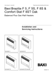
Please leave these instructions with the user © Baxi Heating U.K. Limited 2010. Baxi Brazilia F 5, F 5S, F 8S & Comfortstat 2 F 8ST Balanced Flue Gas Wall Heaters Installation and Owner Guide. Baxi Brazilia F 5 Baxi Brazilia F 5S Baxi Brazilia F 8S Baxi Brazilia F 8ST Comfortstat 2 5131922 / 04 © Baxi Heating U.K. Limited 2010. Natural Gas Propane Baxi Brazilia F 5 G.C.No. 35 075 01 Baxi Brazilia F 5 Propane G.C.No. 35 075 04 Baxi Brazilia F 5S Mahogany G.C.No. 35 075 02 Baxi Brazilia F 5S Oak G.C.No. 35 075 02 Baxi Brazilia F 5S Grey Propane G.C.No. 35 075 05 Baxi Brazilia F 8S Grey Propane G.C.No. 35 075 06 Baxi Brazilia F 8S Mahogany G.C.No. 35 075 03 Baxi Brazilia F 8S Oak G.C.No. 35 075 03 Baxi Brazilia Comfortstat 2 F8ST Oak G.C.No. 35 075 10 Baxi Heating Ltd is one of the leading manufacturers of domestic heating products in the UK. Our first priority is to give a high quality service to our customers. Quality is built into every Baxi product products which fulfil the demands and needs of customers, offering choice, efficiency and reliability. To keep ahead of changing trends, we have made a commitment to develop new ideas using the latest technology - with the aim of continuing to make the products that customers want to buy. We hope you get a satisfactory service from Baxi. If not, please let us know. © Baxi Heating U.K. Limited 2010. All rights reserved. No part of this publication may be reproduced in any material form (including photocopying), stored in any medium by electronic means (including in any retrieval system or database) or transmitted, in any form or by any means, whether electronic, mechanical, recording or otherwise, without the prior written permission of the copyright owner. Applications for the copyright owner's permission to reproduce any part of this publication should be made, giving details of the proposed use, to the following address: The Company Secretary, Baxi Heating UK Limited, Brooks House, Coventry Road, Warwick, CV34 4LL Warning: Any person who does any unauthorised act in relation to a copyright work may be liable to criminal prosecution and civil claims for damages. Warning: Any person who does any unauthorised act in relation to a copyright work may be liable to criminal prosecution and civil claims for damages. Baxi is a BS-EN ISO 9001 Accredited Company 2 For GB/IE only. © Baxi Heating U.K. Limited 2010. Installer Guide Contents Section Page(s) Installer guide 3 - 17 1.0 Introduction 2.0 3.0 4.0 5.0 6.0 7.0 8.0 9.0 Technical Data 6-7 Site Requirements 8 - 10 Installation 11 Commissioning the Appliance 12 Annual Servicing 13 Changing Components 14 - 17 Fault Finding 18 Short Parts List 19 Owner guide 4-5 20- 27 1.0 Warnings 1.1 Safe Installation 1.2 In case of gas leaks 1.3 Guarding 21 21 21 21 1.4 Servicing your Appliance 2.0 Introduction & Operation 2.1 Introduction 2.2 Operating units that are not fitted with the Comfortstat control 2.3 Operating units fitted with the Comfortstat control 3.0 Cleaning & Clearances 21 22 22 23 24 3.1 Cleaning the Appliance 3.2 Clearances 4.0 Spares & Running costs 4.1 Spare Parts 4.2 Running Costs 5.0 Warranty & Service 24 24 25 25 25 26 22 Installer Before continuing any further with the installation of this appliance please read the following guide to manual handling: The lifting weight of this appliance is as below: Gross weight (kg) Model F5 18.0. F 5S 19.1. F 8S & F 8ST 24.4. One person should be sufficient to lift the fire. If for any reason this weight is considered too heavy then obtain assistance. When lifting always keep your back straight. Bend your legs and not your back. Avoid twisting at the waist. It is better to reposition your feet. Avoid upper body/top heavy bending. Do not lean forward or sideways whilst handling the fire. Always grip with the palm of the hand. Do not use the tips of fingers for support. Always keep the fire as close to the body as possible. This will minimise the cantilever action. Use gloves to provide additional grip. Always use assistance if required. 3 © Baxi Heating U.K. Limited 2010. Installer Guide 1.0 Introduction IMPORTANT: The appliance must only be used on its designated gas type. This is indicated on the information label. 1.1 Description 1. The Baxi Brazilia F is a range of room sealed gas convector appliances designed to be used with gas type G20 (Natural Gas) at supply pressure 20 mbar. When converted using the below kits the non thermostatic range is also suitable for use with gas type G31 (Propane) at supply pressure 37 mbar. LPG Kits F 5 & F 5S 5110284 F8S 5110285 Fig. 1 Baxi Brazilia F 5 The procedure for installation, servicing etc. is the same for both Natural Gas and Propane models. 2. The appliance provides warm air by natural convection and flueing is by means of a concentric balanced flue arrangement. 3. Except for Comfortstat, the appliance is controlled by a control knob which operates the ignition and alters the heat output. The control knob has five positions giving a choice of three output rates: OFF Position Baxi Brazilia F 5S Position Fig. 2 l IGNITION Position Position LOW ll lll MEDIUM 4. (Comfortstat only) The appliance is controlled by an upper control knob which operates the ignition and burner setting. Fig. 3 Baxi Brazilia F 8S Position OFF Position IGNITION Position LOW Position HIGH A lower control knob alters the temperature setting, the knob has seven positions. Baxi Brazilia F 8ST Fig. 4 4 © Baxi Heating U.K. Limited 2010. Installer Guide 1.0 Introduction 1.2 Installation 1. The appliance is suitable for installation only in G.B. and I.E. and should be installed in accordance with the rules in force. For Ireland install in accordance with I.S.813 “Domestic gas installations”. In the UK the installation must be carried out by a Gas safe register Installer or other competent person (GAS SAFE REGISTER or CORGI engineer outside of UK) and be in accordance with the relevant requirements of Gas Safety (Installation and Use) Regulations latest edition, the Building Regulations issued by the Department of the Environment, Building Standards (Scotland) (Consolidation) Regulations issued by the Scottish Development Department and the Local Building Regulations. Where no specific instructions are given, reference should be made to the relevant BRITISH STANDARD CODES OF PRACTICE. 2. This appliance must be installed in accordance with the manufacturers instructions and the rules in force. Notice 3. Read the instructions before installing or using this appliance. Discolouration of wall surfaces Most heating appliances generate warm air convection currents and transfer heat to any wall surface against which they are situated. Some soft furnishings (such as blown vinyl wallpapers) may not be suitable for use where they are subject to temperatures above normal room levels and the manufacturer's advice should be sought before using this type of wall covering adjacent to any heating appliance. The likelihood of wall staining from convected air currents will be increased in environments where high levels of tobacco smoke or other contaminants exist. 1.3 NOTE: All illustrations show F 5S, unless otherwise indicated. The procedure for installation, commissioning, servicing etc. is the same for all Brazilia F models. B.S. Codes of Practice STANDARD B.S. 6891 B.S. 5440: Pt. 1 B.S. 5871 Pt.1 SCOPE Gas Installation. Flues. Installation of fires, convector heaters Important Information This product uses insulation board and gaskets containing Refractory Ceramic Fibres (RCF), which are man-made vitreous silicate fibres. Excessive exposure to these materials may cause irritation to eyes, skin and respiratory tract. Consequently, it is important to take care when handling these articles to ensure that the release of dust is kept to a minimum. To ensure that the release of fibres from these RCF articles is kept to a minimum, during installation and servicing we recommend that you use a HEPA filtered vacuum to remove any dust and soot accumulated in and around the fire before and after working on the fire. When replacing these articles we recommend that the replaced items are not broken up, but are sealed within a heavy duty polythene bag, clearly labelled as RCF waste. RCF waste is classed as a stable, non-reactive hazardous waste and may be disposed at a landfill licenced to accept such waste. Protective clothing is not required when handling these articles, but we recommend the use of suitable gloves to prevent irritation. We also recommend you follow the normal hygiene rules of not smoking, eating or drinking in the work area and always wash your hands before eating or drinking. This appliance does not contain any component manufactured from asbestos or asbestos related products. 5 © Baxi Heating U.K. Limited 2010. Installer Guide 2.0 Technical Data F 5 & F 5S Natural Gas Category of Appliance II2H3P The appliance is set for Gas Type G20 at 20mbar. Heat Input (gross) kW Btu/h High 2.05 7,000 Med 1.41 4,800 Low 0.86 3,000 Heat Output (gross) High kW 1.5 Btu/h 5,100 Med 0.98 3,350 Low 0.57 1,950 Setting Pressure 6 Cold mbar in wg 19.7 ± 0.75 7.9 ± 0.3 Injector Size CO2 Nox Class 3 Gas Rate on HIGH 0.195 m3/h (6.89 ft3/h) Gas Connection R 1/4 (1/4 BSP external) Ignition Piezo Spark Packed Weight F5 18 kg (39.7 lbs) F 5S 18.4 kg (40.6 lbs) Dimensions Height Width Depth (from the wall) F5 394mm 426mm 126mm F 5S 394mm 450mm 128mm Controls Rotary gas tap allowing manual adjustment between low, medium and high output. Flame failure device. Thermocouple Output 8-13mv Heat Exchanger Cast Iron F 8S & F 8ST Natural Gas Category of Appliance F 8S II2H3P Category of Appliance F 8ST I2H The appliance is set for Gas Type G20 at 20mbar. Except Comfort Except Comfort Stat Comfort Stat Stat Heat Input (gross) kW Btu/h High Med Low Low 3.06 2.21 1.50 1.27 10,440 7,540 5,118 4,333 Except Comfort Except Comfort Stat Comfort Stat Stat Heat Output (gross) High Med Low Low kW 2.26 1.48 0.6 0.80 Btu/h 7,700 5,050 2,047 2,730 Setting Pressure F Range Cold mbar in wg 19.25 ± 0.75 7.7 ± 0.3 Setting Pressure Comfortstat Cold mbar in wg 20.00 ± 1.00 8.0 ± 0.4 Injector Size CO1 Nox Class 2 Gas Rate on HIGH 0.29 m3/h (10.28 ft3/h) Gas Connection F 8S - R 1/4 (1/4 BSP external) F 8ST - 8mm nut and olive Ignition Piezo Spark Packed Weight F 8S & F 8ST 24.4 kg (54 lbs) Dimensions Height Width Depth (from the wall) F 8S 430mm 516mm 152mm Controls Non Thermostat Rotary gas tap allowing manual adjustment between low, medium and high output. Flame failure device. Controls Comfortstat Rotary thermostat allowing a lowt position and adjustment between low and high temperature settings. Flame failure device. Thermocouple Output 8-13mv Heat Exchanger Cast Iron F 8ST 430mm 516mm 170mm © Baxi Heating U.K. Limited 2010. Installer Guide 2.0 Technical Data F 5 & F 5S Propane (When converted using kit No. 5110284) Category of Appliance II2H3P The appliance is set for Gas Type G31 at 37mbar. F 8S Propane (When converted using kit No. 5110285) Category of Appliance II2H3P The appliance is set for Gas Type G31 at 37mbar. Heat Input (gross) kW Btu/h High 2.05 7,000 Med 1.41 4,800 Low 0.86 3,000 Heat Input (gross) kW Btu/h Heat Output (gross) High kW 1.5 Btu/h 5,100 Med 0.98 3,350 Low 0.57 1,950 Heat Output (gross) High kW 2.26 Btu/h 7,700 Setting Pressure Cold mbar in wg Setting Pressure 36.5 ± 1 14.6 ± 0.4 High Med 3.06 2.21 10,440 7,540 Med 1.48 5,050 Cold mbar in wg Low 1.27 4,333 Low 0.80 2,730 36.5 ± 1 14.6 ± 0.4 Injector Size 74 Injector Size 90 Nox Class 3 Nox Class 2 Gas Rate on HIGH 0.077 m3/h (0.146 kg/h) Gas Rate on HIGH 0.115 m3/h (0.218 kg/h) Gas Connection R 1/4 (1/4 BSP external) Gas Connection R 1/4 (1/4 BSP external) Ignition Piezo Spark Ignition Piezo Spark Packed Weight F5 18 kg (39.7 lbs) F 5S 18.4 kg (40.6 lbs) Packed Weight F 8S 24.4 kg (54 lbs) Dimensions Height Width Depth (from the wall) F5 394mm 426mm 126mm F 5S 394mm 450mm 128mm Dimensions Height Width Depth (from the wall) F 8S 430mm 516mm 152mm Controls Rotary gas tap allowing manual adjustment between low, medium and high output. Flame failure device. Controls Rotary gas tap allowing manual adjustment between low, medium and high output. Flame failure device. Thermocouple Output 8-13mv Thermocouple Output 8-13mv Heat Exchanger Cast Iron Heat Exchanger Cast Iron 7 © Baxi Heating U.K. Limited 2010. Installer Guide 3.0 Site Requirements 3.1 Location 1. The appliance must be fitted on a suitable outside wall to meet the requirements of the balanced flue arrangement. 2. For applications involving walls constructed from or comprising of combustible material, reference should be made to the requirements of B.S. 5871 and Building Regulations. 3. Building Regulations will require the flue duct to be separated from any combustible material within the wall by a non-combustible sleeve enclosing an annular air space of at least 25mm (1 in) around the flue duct. 4. If the outer face of the wall is combustible, a plate of metal (or other non-combustible material) should be fitted over the flue duct extending at least 50mm (2 in) around the terminal. 5. Further guidance on timber frame construction is given in the Institute of Gas Engineers UP7. “Guide for Gas Installations in Timber Framed Dwellings”. 3.2 Clearances 1. The appliance must be fitted on a vertical flat non-combustible wall. Any combustible wall coverings should be removed from within the area of the outer case. 2. Internally the appliance must not be fitted under a shelf or sill which has a projection of more than 150mm (6 in). 3. Curtains or a shelf must not be closer than 140mm (51/2 in) (F 5 & F 5S), 89mm (31/2 in) (F 8S & F 8ST) from top of outer case. 4. The bottom of the outer case must be a minimum of 72mm (27/8 in) from the floor. Subject to this minimum dimension it is recommended that the appliance is fitted as close to the floor as possible for optimum distribution of heat. 5. Minimum side clearance form any wall or fixed furniture to the outer case is: Left hand side: 45mm (13/4 in) Right hand side: 57mm (21/4 in) IMPORTANT: LPG Models. This appliance must not be installed below ground in basements, cellars, etc. unless these are open to ground level on one side. For further guidance see BS 5871 Pt.1. 8 Installer Guide 3.0 Site Requirements Fig. 5 3.3 Flue Position 1. The siting of the balanced flue terminal must meet the following conditions: a. Where the flue terminal of the appliance is beneath any opening (that is to say, any part of a window capable of being opened, or any ventilation inlet or similar opening) no part of the terminal shall be within 300mm (1 ft), measured vertically from the bottom of the opening. Fig. 6 Fig. 7 A* B* C* D E F G H I J K L (side view). Angle of drop shown exaggerated. Terminal Position with Minimum Distance (mm) Directly below an openable window or other opening, e.g. an air brick. Below gutters. Below eaves, soil pipes or drain pipes. Below balconies or car port roof From vertical drain pipes and soil pipes. From internal or external corners. Above ground, roof or balcony level. From a surface facing a terminal. From a terminal facing a terminal. Vertically from a terminal on the same wall. Horizontally from a terminal on the same wall. For an opening in a car port (e.g. door, window) into a dwelling. 300 300 300 600 300 600 300 600 600 1500 300 1200 *In addition, the terminal should not be nearer than 300mm to an opening in the building fabric formed for the purpose of accommodating a built-in element such as a window frame or door frame (Fig. 8). b. Where the flue terminal of the appliance is less than 2m (6 ft) above the level of any ground, balcony, flat roof or place to which any person has access and which adjoins the wall in which the flue terminal is situated, the terminal shall be protected by a guard. c. The guard must be screwed to the wall over the flue terminal and be at least 50mm (2 in) clear of any part of the terminal. A suitable guard is available direct from Baxi Heating, Part No. 080266 (Fig. 6). d. Not within 300mm (1 ft) of ground level. 2. Fig. 4 shows the positioning of the flue terminal relative to buildings and other structures. 3. If the outer face of the outside wall is of combustible material (timber, etc.) a metal or other non-combustible material plate should be fitted round the flue terminal so that it extends not less than 50mm (2 in) around the terminal. A 179mm (7 in) square or a 230mm (9 in) diameter circular plate will meet the requirement. 4. The flue should run horizontally, or with a slight drop to the terminal, in order to prevent rain entry (Fig. 7). Fig. 8 © Baxi Heating U.K. Limited 2010. 9 © Baxi Heating U.K. Limited 2010. Installer Guide 3.0 Site Requirements 3.4 Flue Dimensions 1. The standard appliance is supplied with flue ducting which is adjustable to accommodate wall thicknesses from 248mm (93/4 in) to 349mm (133/4 in). Flue Option Wall Thickness F8S & F8ST F5 & F5S 381mm-483mm (15in - 19in) Part No 243857 Not available 520mm-610mm (201/2in - 24in) Part No 243848 Not available 2. Three further flue terminals are available as optional extras to suit the wall thicknesses indicated in the table opposite. 3.5 Ventilation 1. The appliance is room sealed and therefore requires no purpose built ventilation. 2. It is intended for use in habitable rooms, and must not be fitted in cupboards or confined compartments. 3.6 Gas Supply 1. The inlet connection is located on the gas tap at the bottom right hand side of the appliance. Comfortstat models have an 8mm nut and olive connection. All other models use R1/4 (1/4 BSP external). 2. A gas service cock must be fitted in the supply to the appliance with a disconnecting union between the service cock and the inlet connection. NOTE: If the gas supply is run either to the left or right on leaving the appliance, at least the first 51mm (2 in) from the inlet connection must run vertically downwards to avoid the outer case fouling the gas supply. 10 © Baxi Heating U.K. Limited 2010. Installer Guide 4.0 Installation 4.1 Preparation 1. Ensure that the length of the flue ducting is suitable for the wall thickness. 2. Select a position for the appliance. Using the template supplied, mark the position of the flue ducting and the four fixing holes. Ensure that the template is vertical (Fig. 9 or 10 depending on model). 8 3. Cut a neat hole 127 - 140mm (5 - 51/2 in) in the wall for the flue. 4. Drill and plug the wall at the four fixing holes using a 6mm (1/4 in) drill. Fig. 9 (F 8S & F 8ST) 4.2 Fitting the Appliance 1. Slide the flue duct and terminal assembly into the flue outlet at the rear of the appliance. Ensure that the flue duct spotwelds are not at the bottom. 2. To determine the flue length, measure the wall thickness and add 20mm (3/4in). Adjust the distance from the back of the airbox and the joint between the terminal and air duct to this dimension. Using the length of flue tape provided fix this dimension by taping up the joint between the flue duct assembly and the flue outlet. 5 3. Offer the appliance up to the wall pushing the terminal and flue ducting through the wall. Fig. 10 (F 5 & F 5S) 4. Ensuring that the appliance is level, secure it to the wall using four suitable screws and washers. Check that the wall sealing ring is correctly positioned and seals against the wall (Fig. 11). 5. Ensure that the flue terminal protrudes sufficiently on the outside wall face (Fig. 11). Make good as appropriate. 6. Connect the gas supply incorporating a gas service cock and a disconnecting union between the service cock and the inlet connection. 7. Check for gas soundness (B.S. 6891). Fig. 11 (Top View) 11 © Baxi Heating U.K. Limited 2010. Installer Guide 5.0 Commissioning the Appliance 5.1 Commissioning the Appliance 1. Turn on the gas service cock. 2. Where applicable, fit the control knob onto the control tap spindle (Fig. 12). 3. Purge any air from the system. 4. Non Comfortstat models - Remove the pressure test point screw. Comfortstat models - Loosen the pressure test point screw. Control Knob Fit a pressure gauge to the pressure test point (Fig. 12). Pressure Test Point Fig. 12 Igniter removed for clarity Comfortstat models only Pressure Test Point at front marked 5. Push the control knob in and turn anticlockwise to the ignition ( ) / ( ) position. The main burner should light. Keep the control knob pushed in for 20 seconds. If the burner fails to remain alight repeat the procedure. Check that the gas supply is correct by measuring the pressure at the test point on the gas control tap. 6. No adjustment is provided on the appliance. If it is found that the test pressure is not within the tolerances given, consult the gas supplier. 7. Push in and turn the control knob back to the OFF ( ) position. Remove pressure gauge and replace the pressure test point screw. 8. Relight the appliance and check for gas soundness. N.G. Setting Pressure (Cold/High Rate) F5 & F5S F8S 19.7 ± 0.75mbar 19.25 ± 0.75mbar (7.9 ± 0.3in wg) (7.7 ± 0.3in wg) 5.2 Fitting the Outer Case Before fitting the case it is important that the details on the last page of this guide are completed. F8ST Comfortstat 2 20.00 ± 1.0mbar (8.0 ± 0.4in wg) 1. Push in and turn the control knob back to the OFF ( ) position. L.P.G. Setting Pressure (Cold/High Rate) 2. On models not fitted with the Comfortstat control, remove the knob from the appliance by gently pulling the knob forward (Fig. 12). F5 & F5S 36.5 ± 1mbar (14.6 ± 0.4in wg) F8S 36.5 ± 1mbar (14.6 ± 0.4in wg) Fig. 13 3. Fit the outer case by locating the slots in the outer case rear strip onto the four mounting lugs on the wall brackets (Fig. 14). 4. Where applicable, replace the control knob (Fig. 14). 5.3 Instructing the User 1. Explain how to ignite the appliance and alter the heat settings. 2. Show the position of the external gas service cock. Mounting Lugs Viewing Window 12 Fig. 14 3. Instruct the user that the bottom and top of the case must never be obstructed in any way and emphasise that clothes etc must never be hung over the appliance to dry as this will cause overheating and possible damage. 4. Hand over this guide and recommend that for reasons of safety and economy the appliance should be serviced annually by a competent person. © Baxi Heating U.K. Limited 2010. Installer Guide 6.0 Annual Servicing 6.1 Servicing the Appliance 1. For reasons of safety and economy the appliance should be serviced annually. Outer Case 2. Before servicing please read Section 1.3 Important Information. Fig. 15 3. Turn off the gas supply and ensure that the appliance is cold. 4. On models not fitted with the Comfortstat control, remove the control knob by pulling forward. Control Knob 5. Remove the case by easing upward and forward until it is clear of its retaining lugs. 6. Undo the heat exchanger retaining nuts and washers (Fig. 16) and draw the casting forward off the locating studs. Fig. 16 7. Remove the three screws holding the burner retaining plate to the airbox and undo the thermocouple nut from the gas tap (Fig. 17 & 20). 8. Ease the thermocouple and electrode lead from the rubber grommet (Fig. 18). Rope Seal Heat Exchanger Casting 9. Disengage the burner from the injector and pull the electrode lead off the spark electrode (Fig. 17). Burner Retaining Plate 10. Check that the insulation is undamaged. Replace if necessary. (Fig. 19). Fig. 17 11. Remove and clean the injector and sealing washer. The injector must not be cleaned with a needle or wire (Fig. 20). If the sealing washer is damaged it must be replaced. Burner Gauze Spark Electrode Flue Outlet Tube Burner Flame Ports Insulation 12. Check that the flue outlet tube is clear (Fig. 19). 13. Brush away any dirt from the heat exchanger casting. If necessary clean the viewing window. 14. With a light brush carefully remove deposits from the spark electrode, burner flame ports and the burner gauze (Fig. 17). Fig. 18 15. Replace the rope seal in the heat exchanger casting if it is damaged in any way (Fig. 16). Also examine the thermocouple and replace if necessary. Grommet Electrode Lead Fig. 19 Thermocouple wires 16. Re-assemble the injector, washer and burner assembly in reverse order of dismantling. Ensure that the spark gap is correct ie. 3.5mm ± 0.5mm. Check that the burner is horizontal and correctly positioned on the injector with the gauze covering the primary aeration hole. 17. Check the gas pressure at the test point on the gas control tap. If the pressure is not within the tolerance, (see Section 2.0 Technical Data) the gas supply to the unit needs to be investigated. Gas Tap 18. Check that the burner ignition is satisfactory. Ensure that the thermocouple/electrode lead grommet is correctly positioned and re-fit the heat exchanger casting. Thermocouple nut 19. Check for gas soundness. Injector Washer Fig. 20 20. Fit the case and control knob (where applicable) and re-check that the ignition is satisfactory. Electrode Lead 13 © Baxi Heating U.K. Limited 2010. Installer Guide Fig. 21 7.0 Changing components on models without the Comfortstat control 7.1 Mounting Lugs Changing Components 1. Before changing any components please read Section 1.3 Important Information. 2. Turn off the gas supply and ensure that the appliance is cold. 3. Remove the control knob by pulling forward, then remove the case by easing upwards and forwards until it is clear of its retaining lugs (Fig. 21). 4. After changing any components re-commission the appliance Fig. 22 7.2 Tabs Electrode Lead Igniter Burner Retaining Plate Piezo Unit (Fig. 22). 1. Pull off the spark lead at the rear of the igniter. 2. Straighten the tabs securing the piezo unit to the tap retaining plate and remove. 3. Fit the new piezo unit and twist the tabs slightly to secure. Fig. 23 4. Replace all components in the reverse order of dismantling. Burner Gauze 7.3 Spark Electrode Flue Outlet Tube Burner Flame Ports Insulation Fig. 24 Gas Control Tap 1. Undo the heat exchanger retaining nuts and washers and draw the casting forwards off the locating studs. 2. Remove the three screws holding the burner retaining plate to the airbox and undo the thermocouple nut from the gas tap (Fig. 23 & 25). 3. Ease the thermocouple and electrode leads from the rubber grommet (Fig. 24). 4. Disengage the burner from the injector and pull the electrode lead off the spark electrode (Fig. 23). 5. Pull off the spark electrode lead at the rear of the igniter (Fig. 25). Grommet Electrode Lead 6. Remove the supply pipe from the gas tap. 7. Undo the nut holding the gas tap to its retaining bracket, and disengage the tap from the bracket (Fig. 25). Thermocouple wires Gas Tap Locating Bracket Thermocouple wires Gas Tap Fig. 25 Injector Washer 14 Electrode Lead 8. Remove the injector and sealing washer. If the washer is damaged it must be replaced. 9. On re-assembly ensure that the airbox sealing grommet is correctly positioned and check for gas soundness. © Baxi Heating U.K. Limited 2010. Installer Guide Fig. 26 7.0 Changing components on models without the Comfortstat control 7.4 Burner 1. Undo the heat exchanger retaining nuts and washers and draw the casting forwards off the locating studs (Fig. 26). Rope Seal Heat Exchanger Casting Burner Retaining Plate Fig. 27 3. Ease the thermocouple and electrode lead from the rubber grommet (Fig. 28). 4. Disengage the burner from the injector and pull the electrode lead off the spark electrode (Fig. 27). 5. Remove the intake gauze from the burner inlet and undo the screws securing the burner to its’ retaining plate, noting the position of the shield at the left hand side (Fig. 27). Spark Electrode Thermocouple 2. Remove the three screws holding the burner retaining plate to the airbox, also remove the insulation and undo the thermocouple nut from the gas tap (Fig. 27 & 29). Electrode Lead Burner Gauze 6. Undo the screw securing the spark electrode to the burner. Fit the electrode to the new burner (Fig. 27). 7. Fit the intake gauze to the burner inlet ensuring that it covers the primary aeration hole (Fig. 27). 8. Reassemble in reverse order of dismantling. Shield 7.5 Injector 1. Remove the burner as described in sections 7.4.1 to 7.4.4 . 2. Undo the injector and sealing washer, retaining the washer for use with the new injector. If the washer is damaged it must be replaced (Fig. 29). Fig. 28 3. Reassemble in reverse order of dismantling. Grommet 7.6 Electrode Lead Thermocouple 1. Remove the burner as described in sections 7.4.1 to 7.4.4 . Thermocouple wires 2. Undo the nut retaining the thermocouple tip to the burner bracket and withdraw the thermocouple (Fig. 27). Gas Tap 3. Bend the new thermocouple in a similar manner to the one removed. Avoid any sharp bends. Thermocouple nut 4. On reassembly ensure that the airbox sealing grommet is correctly positioned. Injector Washer Fig. 29 Electrode Lead 15 © Baxi Heating U.K. Limited 2010. Installer Guide 8.0 Changing components on models with the Comfortstat control Fig. 30 8.1 Changing Components 1. Before changing any components please read Section 1.3 Important Information. 2. Turn off the gas supply and ensure that the appliance is cold. Mounting Lugs 3. Remove the case by easing upward and forward until it is clear of its retaining lugs (Fig. 30). 4. After changing any components re-commission the appliance 8.2 Gas Control Tap 1. Undo the heat exchanger retaining nuts and washers and draw the casting forward off the locating studs. Once clear of the studs the casting will need to be moved to the left to avoid the gas tap locating bracket. Burner Retaining Plate Fig. 31 2. Remove the three screws holding the burner retaining plate to the airbox, also remove the insulation and undo the thermocouple nut from the gas tap (Fig. 31 & 33). Burner Gauze 3. Ease the thermocouple and electrode leads from the rubber grommet (Fig. 32). Spark Electrode Flue Outlet Tube Burner Flame Ports Insulation 4. Disengage the burner from the injector and pull the electrode lead off the spark electrode 5. Remove the supply pipe clamp and supply pipe from the gas tap. 6. Unscrew and remove the pipe that connects the gas tap to the injector carrier. Fig. 32 7. Unclip the thermostat phial. 8. Unscrew and remove the two screws that secure the gas tap to the gas tap locating bracket then ease the gas tap forward and clear of the bracket. Grommet 9. On re-assembly ensure that the airbox sealing grommet is correctly positioned and check for gas soundness. Electrode Lead Thermocouple Seal Injector Gas Tap Washer Lock nut Gas Tap Locating Bracket Fig. 33 16 Injector carrier © Baxi Heating U.K. Limited 2010. Installer Guide Fig. 34 8.0 Changing components on models with the Comfortstat control 8.3 Burner 1. Undo the heat exchanger retaining nuts and washers and draw the casting forward off the locating studs. Once clear of the studs the casting will need to be moved to the left to avoid the gas tap locating bracket. (Fig. 34). Rope Seal 2. Remove the three screws holding the burner retaining plate to the airbox, also remove the insulation and undo the thermocouple nut from the gas tap (Fig. 35 & 37). Heat Exchanger Casting Burner Retaining Plate 3. Ease the thermocouple and electrode lead from the rubber grommet (Fig. 36). 4. Disengage the burner from the injector and pull the electrode lead off the spark electrode (Fig. 35). Fig. 35 5. Remove the intake gauze from the burner inlet and undo the screws securing the burner to its’ retaining plate, noting the position of the shield at the left hand side (Fig. 35). Spark Electrode Thermocouple Electrode Lead 6. Undo the screw securing the spark electrode to the burner. Fit the electrode to the new burner (Fig. 35). Burner Gauze 7. Fit the intake gauze to the burner inlet ensuring that it covers the primary aeration hole (Fig. 35). Shield 8. Reassemble in reverse order of dismantling. 8.4 Injector 1. Remove the burner as described in sections 8.3.1 to 8.3.4. Fig. 36 2. Undo the injector and sealing washer, retaining the washer for use with the new injector. If the washer is damaged it must be replaced (Fig. 37). Grommet 3. Reassemble in reverse order of dismantling. Electrode Lead Thermocouple 8.5 Thermocouple Seal 1. Remove the burner as described in sections 8.3.1 to 8.3.4. Injector Gas Tap Washer Lock nut 2. Undo the nut retaining the thermocouple tip to the burner bracket and withdraw the thermocouple. 3. Bend the new thermocouple in a similar manner to the one removed. Avoid any sharp bends. Gas Tap Locating Bracket Injector carrier 4. On reassembly ensure that the airbox sealing grommet is correctly positioned. Fig. 37 17 © Baxi Heating U.K. Limited 2010. Installer Guide Ensure all installation criteria have been satisfied before performing Fault Finding (e.g. flue terminal position). 7±1.5mm Fig. 38 18 3.5±0.5mm 8.0 Fault Finding © Baxi Heating U.K. Limited 2010. Installer Guide 9.0 Short parts list Key G.C. No. No. D G/R/S A 243262 234637 Knob Control (F 8S) E26568 Grey 205894 Beige 243261 234643 Knob Control (F 8ST) E94629 Beige 3002698 D 205837 Burner (F 5 / F 5S) 224041 E 205864 Burner (F 8S / F 8ST) 223963 F 205873 Electrode Spark 223940 G E01357 Igniter/Gas Tap (F 5 / F 5S) E01358 Igniter/Gas Tap (F 8S) 243194 243202 H 393734 Piezo Igniter/Generator 042941 I 381941 Injector (F 5 / F 5S) 224047 J 381942 Injector (F 8S / F 8ST) 224104 K 205791 Washer (For injector) 082365 L 205844 Insulation (F 5 / F 5S) 224048 M E01359 Insulation (F 8S / F 8ST) N 155654 O E01360 Thermocouple 243215 P 384248 Tap Mag Unit (Not F 8ST) 082462 Q E94622 Thermostat / Gas Control 3002927 C H O L N M F A Manufacturers Part No. Knob Control (F 5 / F 5S) E26513 Grey 205887 Beige B E Description 223971 Lead Electrode (For models not fitted with Comfortstat control) 043043 For LPG models only B/C P R S T I/J/T/U Q U E26556 Igniter / Gas Tap Assy. LPG (F 5 / F 5S) 243195 E26574 Igniter / Gas Tap Assy. LPG (F 8S) 243203 E26522 Injector LPG (F 5 / F 5S) 243295 E23577 Injector LPG (F 8S) 243296 K 19 © Baxi Heating U.K. Limited 2010. Owner Guide. Baxi Brazilia F 5 Baxi Brazilia F 5S Baxi Brazilia F 8S Baxi Brazilia F 8ST Comfortstat 2 © Baxi Heating U.K. Limited 2010. Owner Guide 1.0 Warnings 1.1 Safe Installation 1. The appliance is suitable for installation only in G.B. and I.E. and should be installed in accordance with the rules in force. For Ireland install in accordance with I.S.813 “Domestic gas installations”. The installation must be carried out by a Corgi Registered Installer or other competent person and be in accordance with the relevant requirements of Gas Safety (Installation and Use) Regulations latest edition, the Building Regulations issued by the Department of the Environment, Building Standards (Scotland) (Consolidation) Regulations issued by the Scottish Development Department and the Local Building Regulations. Where no specific instructions are given, reference should be made to the relevant BRITISH STANDARD CODES OF PRACTICE and Installation Specifications. Notice Discolouration of wall surfaces Most heating appliances generate warm air convection currents and transfer heat to any wall surface against which they are situated. Some soft furnishings (such as blown vinyl wallpapers) may not be suitable for use where they are subject to temperatures above normal room levels and the manufacturer's advice should be sought before using this type of wall covering adjacent to any heating appliance. The likelihood of wall staining from convected air currents will be increased in environments where high levels of tobacco smoke or other contaminants exist. 2. This appliance must be installed in accordance with the manufacturers instructions and the rules in force. 3. Read the instructions before installing or using this appliance. 1.2 In case of gas leaks If a gas leak is found or suspected, immediately turn off the gas supply at the meter or tank as appropriate and contact your Installer, British Gas Emergency (under 'Gas' in the phone directory) or the gas supplier. 1.3 Guarding During use the top and front of the appliance are working surfaces and become very hot. It is recommended that a guard conforming with B.S. 8423 is used, especially in instances where young children, the elderly, the infirm or pet animals are likely to be present. WARNING: Never Hang Flammable Items Over The Appliance 1.4 Servicing your Appliance For reasons of safety and economy your appliance should be serviced annually. Your Installer or British Gas Service will be able to advise you. The external flue terminal must be kept free from obstruction at all times. If the terminal is less than 2m (6ft.) from ground level, a balcony or other place to which any person has access a suitable terminal guard must be fitted. 21 © Baxi Heating U.K. Limited 2010. Owner Guide 2.0 Introduction & Operation 2.1 Introduction 1. Your Baxi Brazilia F is a room sealed gas convector heater. This means that the gas burning section is sealed from the room in which it is installed. It is connected to a circular flue terminal outside the building. This terminal is the inlet for air required to burn the gas and also the outlet for the flue gases. Fig. 1 2.2 Operating units that are not fitted with the Comfortstat control. Control Knob 1. The appliance is controlled by a knob which is positioned at the lower right on the front of case (Fig. 1). The knob has five positions. Relative positions of markings on side of control knob. OFF Position Position l IGNITION Position Position Position LOW ll lll MEDIUM HIGH 2. To light the appliance (Fig 2a): At the OFF ( ) position push in the control knob as far as possible and still pushing in slowly turn anti-clockwise to the ignition position ( ) to light the burner. Turning the control knob slowly allows gas to enter the burner ready for ignition. Keep the knob pushed in for 20 seconds and the burner should remain alight. If not, repeat the sequence. Fig. 2a Position Position I Position Position II Position III NOTE: Under extreme wind conditions more than one attempt to light the appliance may be required. - OFF - LOW - IGNITION - MEDIUM - HIGH 3. Once lit, the control knob can be altered to any of the three heat settings. 4. When first lit after installation some smells are likely to be emitted. These will quickly clear away with use. OFF IGNITION PRE-SET NOTE: If the appliance goes out at any time wait 3 minutes and repeat the procedure. When changing from one setting to another the knob should always be pushed in slightly. 5. To turn the appliance off: Push the knob in slightly and turn to the OFF ( ) position. MINIMUM TEMPERATURE MAXIMUM TEMPERATURE Fig. 2b 22 © Baxi Heating U.K. Limited 2010. Owner Guide 2.0 Introduction & Operation 2.3 Operating units fitted with the Comfortstat control. 1. The appliance is controlled by two knobs which are positioned at the lower right on the front of case (Fig. 3). The upper knob has four positions. Fig. 3 Control Knob Relative positions of markings on side of upper knob. Position OFF Position IGNITION Position LOW Position HIGH 2. To light the appliance (Fig 3a): At the OFF ( ) position push the upper control knob as far as possible and still pushing in slowly turn anti-clockwise to the ignition position ( ) to light the burner. Turning the control knob slowly allows gas to enter the burner ready for ignition. Keep the knob pushed in for 10 seconds and the burner should remain alight. If not, repeat the sequence. NOTE: Under extreme wind conditions more than one attempt to light the appliance may be required. 3. Once lit, the control knob can be altered to the High or Low heat settings. 4. When first lit after installation some smells are likely to be emitted. These will quickly clear away with use. Fig. 3a Position Position Position Position - OFF - IGNITION - LOW - HIGH Markings on lower knob. NOTE: If the appliance goes out at any time wait 3 minutes and repeat the procedure. When changing from one setting to another the knob should always be pushed in slightly. 5. To adjust the thermostat setting (Fig 3b): The lower control knob alters the temperature setting, the knob has seven positions. 6. To turn the appliance off: Push the knob in slightly and turn to the OFF ( ) position. Fig. 3b 23 © Baxi Heating U.K. Limited 2010. Owner Guide 3.0 Cleaning & Clearances 3.1 Cleaning the Appliance 1. When cold the appliance may be cleaned with a damp cloth and wiped with a soft duster. Do not use abrasive cleaning agents, wax or spray polish. 3.2 Clearances 1. Internally the appliance must not be fitted under a shelf or sill that projects more than 150mm (6in.) 2. Curtains or a shelf must not be closer to the top of the outer case than 140mm (51/2in) for F 5 & F 5S or 89mm (31/2in) for F 8S & F 8ST models. 3. The minimum side clearances from any wall or fixed furniture are:Left hand side 45mm (13/4in) Right hand side 57mm (21/4in) 24 © Baxi Heating U.K. Limited 2010. Owner Guide 4.0 Spares & Running Costs 4.1 Spare Parts 1. If spare parts are required they can be obtained through Baxi Spares Stockists. Please read section 5. 2. Always quote the appliance model name and G.C. number. The G.C. number can be found on page 2 of these instructions. 3. A “Special Needs Adaptor” is available for use with the Baxi Brazilia F. This is designed for customers suffering from arthritis or similar conditions and provides the user with extra leverage when operating the control knob. It is available from Baxi Spares Stockists. 4.2 Running Costs 1. The running cost of the appliance is quoted in kilowatt hours (kWh). The price per kilowatt hour varies and is shown on your gas bill. 2. The table below shows the approximate time taken by the appliance to consume 1 kWh of energy on minimum and maximum rates. F 5 & 5S F 8S F 8ST High 29 mins. 19 mins. 19 mins. Low 1 hour 8 mins. 47 mins. 40 mins. 25 © Baxi Heating U.K. Limited 2010. Owner Guide 5.0 Warranty and Service 5.1 Standard Warranty Terms & Conditions The warranty is for 12 months subject to contract. In the United Kingdom servicing can be carried out either by a heateam service engineer or a GAS SAFE REGISTER engineer. Outside of the United Kingdom servicing can be carried out either by a CORGI or GAS SAFE REGISTER engineer. You must register your fire with heateam, the service division of Baxi Heating UK Limited, either by completing and returning the registration card or calling our free telephone registration line on 0800 032 72 44. It is also a requirement of the warranty that the fire has an annual service (every 12 months) in accordance with the installation and servicing instructions, performed by a GAS SAFE REGISTER engineer, (CORGI or GAS SAFE REGISTER outside of UK), please call on 0844 8711 525. 5.2 Our promise to you If you experience a fault with your new fire, we aim to provide a safe and high quality repair service supported by our dedicated national network of highly skilled engineers. If your installer can’t resolve the problem for you, we will do everything we can to get an engineer out to you as quickly as possible. Nothing in this warranty will affect your statutory rights. 5.3 What you need to do if you experience a problem with the operation of the fire: You should always contact your installer first, because the cause of the fault may not be related to the fire. If your installer confirms that the fault is with the fire and they can’t repair it, our friendly customer service team is on hand to help. Simply call our service division heateam on 08706 090 081 to book an engineer visit or for any general advice that you may need. Our contact centre is open Monday to Friday 8am – 6pm, weekends and Bank Holidays 8.30am – 2pm, excluding Christmas Day and New Years day. 26 When calling heateam, it would be helpful if you could have the following information to hand:1. 2. 3. 4. 5. Fire serial number and fascia code (Located on the information label - See figure 4 on page 27 ). Date of installation Your installer name and address details Fire make and model number Proof of purchase (if you do not have the fire serial number) Note: details 1 – 4 should be recorded on page 27 at the end of this guide. 5.4 What this warranty covers Free of charge repair or replacement of components found to be of faulty manufacture. Free of charge replacement of the complete unit providing the failure is related to a manufacturing fault that cannot be repaired or is uneconomic to repair. 5.5 What this warranty does not cover Repairs to fires which haven’t been installed and commissioned properly and as set out in the installation instructions. Faults caused by inadequate supply of gas or electricity (where applicable). Reimbursement of any third party repair or replacement costs that we haven’t been told about or agreed with you in advance. Compensation or consequential losses (e.g. loss of earnings, business losses, stress and inconvenience) arising from a production breakdown, including repair delays caused by factors outside our reasonable control. © Baxi Heating U.K. Limited 2010. Owner Guide The following pages are to be completed by the installer: Installer Details (Block Capitals) Installer Name Gas Safe Register or Corgi Registration Number. Company Name. Company Address Company Telephone number Company Fax number Model 0 4 8 Serial number (Can be found on information label - See figure 4) Fig. 4 Information label location A LABEL CONTAINING THE SERIAL NUMBER MAY HAVE BEEN PLACED INSIDE THIS BOX. SERIAL NUMBER LABEL TO BE AFFIXED HERE Name B R (Please tick) A Z I L I A F 5 B R A Z I L I A F 5 S B R A Z I L I A F 8 S B R A Z I L I A F 8 S A X I Y Y T Brand B Date of Installation D D M M 27 © Baxi Heating U.K. Limited 2010. Baxi Heating U.K. Ltd manufacture a comprehensive range of products for the domestic heating market. Gas Central Heating Boilers (Wall, Floor and Fireside models). Independent Gas Fires. Renewal Firefronts. Gas Wall Heaters. Solid Fuel Fires. If you require information on any of these products, please telephone the number on the rear of this guide. The Baxi Helpline 0844 8711 565 Callers in the Republic of Ireland telephone 0044 844 8711 565 Valor Fires Wood Lane Erdington Birmingham B24 9QP www.firesandstoves.co.uk