1
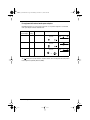
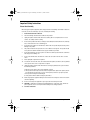
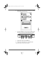
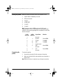
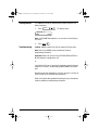
888385_01 Install.book Page 1 Wednesday, November 11, 1998 2:45 PM
••••••••••••••••••••••••••••••••••••••••
SMDR6
Installation Guide
•••••••••••••••••••••••••
888385_01 Install.book Page 2 Wednesday, November 11, 1998 2:45 PM
888385_01 Install.book Page i Wednesday, November 11, 1998 2:45 PM
Safety Installation Instructions
Please Read Carefully
WARNING: To avoid electrical shock hazard to personnel or equipment damage observe the
following precautions when installing telephone equipment:
1.
Never install telephone wiring during a lightning storm.
2.
Never install telephone jacks in wet locations unless the jack is specifically designed for wet locations.
3.
Never touch uninsulated telephone wires or terminals unless the telephone line has been disconnected at the network interface.
4.
Use caution when installing or modifying telephone lines.
The exclamation point within an equilateral triangle is intended to alert the user to the presence of important operating and maintenance (servicing) instructions in the literature
accompanying the product.
This symbol (if applicable) on the product is used to identify the following important information:
For equipment with internal power supplies:
•
Mains nominal AC voltage 110-120 V~ ; 50/60 Hz
•
Mains nominal AC voltage 220-240 V~ ; 50/60 Hz
SMDR6 Regulations i
888385_01 Install.book Page ii Wednesday, November 11, 1998 2:45 PM
For equipment with external mains power adapters:
CAUTION: Intended for use in a protected environment. Use only a Nortel supplied or recommended
mains power adapter marked as indicated below:
Mains Supply
(Input Voltage)
Output
Voltage
Rated Current
Approval Markings
240 Vac
9 Vdc
0.6 A maximum
CLASS II POWER
SUPPLY
- VE
+VE
230 Vac
9 Vdc
0.6 A maximum
CLASS II POWER
SUPPLY
- VE
+VE
110 Vac
9 Vdc
0.6 A maximum
CLASS 2 POWER
SUPPLY
- VE
+VE
NRTL/C
The
Polarity Marking
or
marking on the product indicates compliance with the EU Low Voltage Directive (LVD) and the
Electromagnetic Compatibility Directive (EMCD).
ii SMDR6 Regulations
888385_01 Install.book Page iii Wednesday, November 11, 1998 2:45 PM
Important Safety Instructions
Please Read Carefully
When using your telephone equipment, basic safety precautions should always be followed to reduce the
risk of fire, electric shock and injury of persons, including the following:
1.
Read and understand all instructions.
2.
Follow the warnings and instructions marked on the product.
3.
Unplug this product from the wall outlet before cleaning. Do not use liquid cleaners or aerosol
cleaners. Use a damp cloth for cleaning.
4.
Do not use this product near water, for example, near a bathtub, wash bowl, kitchen sink, or laundry
tub, in a wet basement or near a swimming pool.
5.
Do not place this product on an unstable cart, stand or table. The product may fall, causing serious
damage to the product.
6.
This product should never be placed near or over a radiator or heat register. This product should
not be placed in a built-in installation unless proper ventilation is provided.
7.
Do not allow anything to rest on the power cord. Do not locate this product where the cord will be
abused by persons walking on it.
8.
Do not overload wall outlets and extension cords as this can result in the risk of fire or electric
shock.
9.
Never spill liquid of any kind on the product.
10. To reduce the risk of electric shock, do not disassemble this product, but have it sent to a qualified
service person when service or repair work is required.
11. Unplug this product from the wall outlet and refer servicing to qualified service personnel under
the following conditions:
a. When the power supply cord or plug is damaged or frayed.
b. If the product has been exposed to rain, water or liquid has been spilled on the product, disconnect and allow the product to dry out to see if still operates; but do not open up the product.
c. If the product housing has been damaged.
d. If the product exhibits a distinct change in performance.
12. Avoid using telephone equipment during an electrical storm. There may be a remote risk of electric
shock from lightning.
13. Do not use the telephone equipment to report a gas leak in the vicinity of the leak.
14.
CAUTION: To eliminate the possibility of accidental damage to cords, plugs, jacks, and the telephone equipment, do not use sharp instruments during the assembly procedures.
15.
Save these instructions.
SMDR6 Regulations iii
888385_01 Install.book Page iv Wednesday, November 11, 1998 2:45 PM
Canadian Regulations
Refer to the System Installation Guide for regulatory information.
Note: This equipment may only be connected to the Host equipment (Norstar or Companion equipment)
and may not be connected directly to the Public Switched Telephone Network (PSTN).
This device complies with Part 68 and Part 15 of the FCC Rules and ICES-003 Canadian EMI requirements.
Operation is subjected to the following two conditions (1) This device may not cause harmful interference
and (2) this device must accept any interference received, including interference that may cause undesired operation.
Note: This device complies with Class A EMI requirements when connected to host equipment that meets
Class A and Class B when connected to host equipment that meets Class B.
Do not attempt to repair this equipment. If you experience trouble, call or write for warranty and repair
information.
Nortel (Northern Telecom)
30 Norelco Drive,
Weston, Ontario, M9L 2X6
Canada
For more information call 1-800-4NORTEL.
iv SMDR6 Regulations
888385_01 Install.book Page v Wednesday, November 11, 1998 2:45 PM
US Regulations
Federal Communication Commission (FCC) Notice
FCC registration number: This telephone equipment complies with Part 68, Rules and Regulations, of
the FCC for connection to Host equipment (Norstar or Companion equipment) and may not be connected
directly to the Public Switched Telephone Network (PSTN).
(The FCC registration number appears on a sticker affixed to the bottom of the unit.)
Refer to the regulatory requirements as detailed in the System Installation Guide.
Do not attempt to repair this equipment. If you experience trouble, call or write for warranty and repair
information.
Nortel (Northern Telecom)
640 Massman Drive,
Nashville, TN, 37210
For more information call 1-800-4NORTEL.
SMDR6 Regulations v
888385_01 Install.book Page vi Wednesday, November 11, 1998 2:45 PM
US Regulations continued
EMI/EMC (FCC Part 15)
Note: This device complies with Class A EMI requirements when connected to host equipment that meets
Class A and Class B when connected to host equipment that meets Class B. Consult the System
Installation Guide for the applicable compliance.
For Class A Host equipment
This equipment has been tested and found to comply with the limits for a Class A digital device, pursuant
to Part 15 of the FCC Rules. These limits are designed to provide reasonable protection against harmful
interference in a commercial environment.
This equipment generates, uses and can radiate radio frequency energy and, if not installed and used in
accordance with the instructions, may cause harmful interference to radio communications.
Operation of this equipment in a residential area is likely to cause harmful interference in which case the
user will be required to correct the interference at his own expense.
For Class B Host equipment
This equipment has been tested and found to comply with the limits for a Class B digital device, pursuant
to Part 15 of the FCC Rules. These limits are designed to provide reasonable protection against harmful
interference in a residential installation.
This equipment generates, uses and can radiate radio frequency energy and, if not installed and used in
accordance with the instructions, may cause harmful interference to radio communications.
However, there is no guarantee that interference will not occur in a particular installation.
If this equipment does cause harmful interference to radio or television reception, which can be determined by turning the equipment off and on, the user is encouraged to try to correct the interference by
one or more of the following measures:
•
Reorient or relocate the receiving antenna.
•
Increase the separation between the equipment and receiver.
•
Connect the equipment into an outlet on a circuit different from that to which the receiver is
connected.
•
Consult the dealer or an experienced radio/TV technician for help.
Changes or modifications not expressly approved by the party responsible for compliance could void the
user’s authority to operate the equipment.
vi SMDR6 Regulations
888385_01 Install.book Page 1 Wednesday, November 11, 1998 2:45 PM
Introduction
Installing the Station Message Detail Recording 6 (SMDR6) involves
five steps:
1.
Mounting the SMDR6 unit on the wall.
2.
Connecting the unit to an available station port on the Key
Service Unit (KSU).
3.
Connecting the unit to the printer.
4.
Connecting the power adapter to the SMDR6 and power outlet.
5.
Testing the unit.
This guide provides the steps necessary for installing SMDR6.
Before installing SMDR6, make sure that both the environmental and
electrical requirements are met. Make sure you have all the equipment
necessary to complete the installation.
The environment for the SMDR6 should be:
Environmental
requirements
❏
Temperature ranging from 0 - 50 degrees C (32 - 122 degrees F)
❏
Relative Humidity ranging from 5% - 95% non-condensing
❏
Station Loop Length not exceeding 800 m 24 gauge
❏
Bridge Taps: Not allowed
❏
Loading Coils: Not allowed
IMPORTANT: More than one SMDR6 can be installed per KSU.
Electrical
requirements
Power for the SMDR6 is provided by the 9 Vdc power adapter
connected to an external power source.
SMDR6 Installation Guide 1
888385_01 Install.book Page 2 Wednesday, November 11, 1998 2:45 PM
Parts checklist
Mounting the unit
To install the SMDR6 unit, make sure you have:
❏
DB25 serial connector (provided)
❏
Key Service Unit
❏
Serial Printer
❏
DB25 Serial Cable (max 8 m/ 25 ft)
Note: We recommend a shielded RS-232 cable.
❏
9 Vdc Power Supply (provided)
❏
Two #8 screws (for wall mounting)
❏
Screwdriver
❏
Paper wall mount plate (provided)
The SMDR6 unit must be installed within 800 m (2,660 ft) of the KSU.
To install the unit:
1.
When using .5mm wire (24 AWG), select a location within 800 m
(2,660 ft) of the KSU.
2.
Allow 12.5 cm (5 in) clearance for the line jack, RS-232 port jack
and the power supply connector.
3.
Tape the paper wall mount template to the wall and make sure the
template is plumb.
4.
The marks on the template show where each of the two screws
are placed. Screw two #8 screws into the wall leaving 6 mm
(1/4 in) of each screw exposed. Remove the paper template.
5.
Align the keyhole slots at the back of the SMDR6 unit over the
screws. Push the SMDR6 against the wall. Ensure that the line
jack RS-232 port jack and the power supply jack are at the top of
the SMDR6 unit.
2 SMDR6 Installation Guide
888385_01 Install.book Page 3 Wednesday, November 11, 1998 2:45 PM
6.
Attach the DB25 serial cable to the RS-232 port of the SMDR6
unit by tightening the thumb screws.
7.
Connect the SMDR6 unit’s line jack (next to the DB-25 connector) using a line cord to any unused station port on the KSU.
~
Terminal
(to phone)
Line
(to KSU)
DB-25
9 V DC
LED
8.
Plug the power supply into the SMDR6 unit.
9.
Plug the power supply adapter into a standard AC outlet.
You are now ready to set and connect the printer.
SMDR6 Installation Guide 3
888385_01 Install.book Page 4 Wednesday, November 11, 1998 2:45 PM
Setting the printer Before you connect the printer, make sure the printer is set at:
1.
speed: 1200 to 115200 bits per second
2.
8 bits per character
3.
no parity
4.
no XON, XOFF
5.
1 start bit
6.
1 stop bit
Note: The printer used for SMDR6 can be any RS-232 serial
compatible device such as a serial printer, PC with communication
software or call accounting package with the capability to collect data
from the serial port.
9 Pin
Connector
25 Pin
Signal Name
Connector
1
Not used
2
3
RX /data
From SMDR6
3
2
TX Data
To SMDR6
4
20
DTR
To SMDR6
5
7
Signal Ground
6
6
DSR
7
8
9
Connecting the
printer
Direction
From SMDR6
Not used
5
CTS
From SMDR6
Not used
To connect the printer:
1.
Connect the cable to the RS-232 serial port of the printer.
2.
Make sure that the KSU AC cord and printer are connected to a
power source.
Note: Make sure no stress is placed on any of the port connections.
4 SMDR6 Installation Guide
888385_01 Install.book Page 5 Wednesday, November 11, 1998 2:45 PM
Testing SMDR6
Test SMDR6 by dialing the Administration Feature Code from any
Norstar telephone.
1.
Press
ƒ·•¤
SMDR6 Admin
NEXT
. The display shows:
QUIT
Note: On M7100/M7208 telephones, the second line of the display is
not shown.
2.
Troubleshooting
Press QUIT or
®
.
Problem: SMDR6 Interface Unit will not respond to Feature Code.
Note: Refer to the SMDR6 System Coordinator Guide for
programming information.
Resolution: Make sure you are using an M7100, M7208, M7310 or
M7324 telephone to program the unit.
or
Check that the KSU port is operating by plugging in a working Norstar
telephone. If the port is not operating, plug the SMDR6 into another
port.
Wait 60 seconds after plugging the unit into a new port. It can take up
to 60 seconds for the unit to become operational.
Refer to the Station Message Detail Recording 6 System Coordinator
Guide for additional troubleshooting information.
SMDR6 Installation Guide 5
888385_01 Install.book Page 6 Wednesday, November 11, 1998 2:45 PM
6 SMDR6 Installation Guide
888385_01 Install.book Page 1 Wednesday, November 11, 1998 2:45 PM
888385_01 Install.book Page 2 Wednesday, November 11, 1998 2:45 PM
1-800-4NORTEL
http: / / www.nortel.com/norstar
Norstar is a Trademark of Northern Telecom.
© Copyright Northern Telecom 1998
P0888385 Issue 01
Printed in Canada
••••••••••••••••••••••••••••••••••••••••