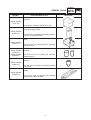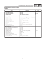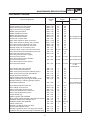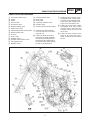
1
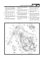
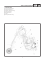
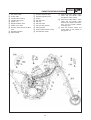
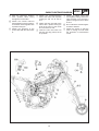
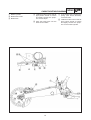
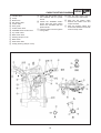
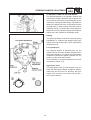
SUPPLEMENTARY
OWNER’S SERVICE MANUAL
WR450F(S) 2-TRAC
5TJ-F8199-E0
WR450F(S) 2-TRAC
SUPPLEMENTARY
OWNER’S SERVICE MANUAL
© 2004 by Yamaha Motor Italia S.p.A.
First edition, March 2004
All rights reserved. Any reproduction or
unauthorized use without the written
permission of Yamaha Motor Italia S.p.A.
is expressly prohibited.
Printed in Italy
CONTENTS
HYDROSTATIC TRANSMISSION ..........................................................................................
WHEN DRIVING ..............................................................................................................
FUNCTION ......................................................................................................................
ADJUSTMENTS ..............................................................................................................
ALTERNATE RATIOS (OPTIONS) ..................................................................................
TOOLS ............................................................................................................................
2
2
2
3
3
3
SPECIAL TOOLS .................................................................................................................. 4
SPECIFICATIONS .................................................................................................................. 6
GENERAL SPECIFICATIONS ........................................................................................ 6
MAINTENANCE SPECIFICATIONS ......................................................................................
CHASSIS ........................................................................................................................
TIGHTENING TORQUES ................................................................................................
CABLE ROUTING DIAGRAM ..........................................................................................
7
7
8
9
REGULAR INSPECTION AND ADJUSTMENTS..................................................................17
MAINTENANCE INTERVALS ........................................................................................ 17
SUPPLEMENTARY INSPECTION AND ADJUSTMENTS ............................................ 17
HYDROSTATIC TRANSMISSION.................................................................................. 17
STEERING DAMPER ADJUSTMENT .......................................................................... 18
FRONT FORK REBOUND DAMPING FORCE ADJUSTMENT .................................... 21
FRONT FORK COMPRESSION DAMPING FORCE ADJUSTMENT .......................... 22
REAR SHOCK ABSORBER SPRING PRELOAD ADJUSTMENT ................................ 23
REAR SHOCK ABSORBER REBOUND DAMPING FORCE ADJUSTMENT .............. 24
REAR SHOCK ABSORBER LOW COMPRESSION DAMPING FORCE
ADJUSTMENT .............................................................................................................. 25
REAR SHOCK ABSORBER HIGH COMPRESSION DAMPING FORCE
ADJUSTMENT .............................................................................................................. 26
CARBURETOR DISASSEMBLY .......................................................................................... 27
TRANSMISSION .................................................................................................................. 28
DRIVE UNIT – TRANSMISSION ASSY ........................................................................ 28
HYDROSTATIC TRANSMISSION.................................................................................. 30
INSPECTION ................................................................................................................ 30
CHANGE OIL IN THE HYDRAULIC MOTOR REDUCTION GEAR HOUSING ............ 30
CHANGE OIL IN THE PUMP TRANSMISSION HOUSING .......................................... 31
CHECK THE WEAR IN THE PUMP TRANSMISSION.................................................. 32
CHANGING THE RATIOS FOR THE PUMP TRANSMISSION .................................... 33
FRONT WHEEL .................................................................................................................... 35
FRONT WHEEL REMOVAL .......................................................................................... 35
FRONT FORK ......................................................................................................................
FRONT FORK DISASSEMBLY......................................................................................
FRONT FORK SPECIFICATION CARD – ÖHLINS® ....................................................
OIL LEVEL ADJUSTMENT ............................................................................................
CHANGING SPRINGS ..................................................................................................
DISMANTLING ..............................................................................................................
ASSEMBLING ................................................................................................................
36
36
38
39
40
42
45
REAR SHOCK ABSORBER ................................................................................................ 48
REAR SHOCK ABSORBER DISASSEMBLY ................................................................ 48
INSPECTION AND MAINTENANCE.............................................................................. 49
STEERING DAMPER .......................................................................................................... 50
DISASSEMBLY AND INSPECTION .............................................................................. 51
1
HYDROSTATIC TRANSMISSION
WHEN DRIVING
Driving a two wheel driven motorcycle is different from driving a conventional motorcycle. The front wheel
drive system, during certain conditions, affects the feeling of the handlebar. In sand, mud and snow the
traction is greatly improved. However in conditions with deep ruts and slippery surfaces the two wheel
drive system might contribute to that the motorcycle feels heavier and more brutal.
WARNING
It is of absolute necessity that the two wheel drive motorcycle has a steering damper. If driven
without steering damper the front wheel, when hitting a root or a stone, can give unduly high
reaction forces to the handlebar.
Before racing, practise as much as possible on different tracks and under different conditions to
get used to the different behaviour of the two wheel drive system.
CAUTION:
On rough road surfaces the front wheel drive can make the steering harder. This is noticeable,
especially when driving aggressively.
When landing after jumps the two wheel drive system will make the front fork feel stiffer due to
that the driving force tries to extend the front fork, especially if the throttle is applied before
touchdown.
NOTE:
This 2-Trac system has been tested extensively on both test tracks and in races. Imperative for the durability and function is high quality material in all components. The high quality materials used are not
always the best suited to provide beautiful surface treatment. As a result we can sometimes see shades
and/or mis-colouring on the anodised aluminium surfaces.
FUNCTION
With the motorcycle free rolling, the pump rotates roughly with the same speed as the
motor.
When throttle is applied the rear wheel and thereby the pump, due to deformation of the
rear tire, starts to rotate a little bit faster even if the driving force is just large enough to
maintain constant speed.
The increased volume stream from the pump causes the speed of the motor to increase,
but to a lesser extent than the pump, thereby creating a driving torque from the front
wheel. Thus the amount of front wheel driving force varies with speed and ground condition and comes in gradually depending on throttle position.
The system has a maximum pressure relieve valve installed to prevent dangerously high
pressure in the system, when for instance on slippery surfaces, where excessive rear
wheel spin can occur.
The oil in the transmission can sometimes get very hot. For instance in sandy, slow
speed conditions or when trying to escape from a mud pit. In order to prevent damage to
the transmission a built in thermostat valve shortcuts the hydraulic circuit, thereby disconnecting the front wheel drive. When this occur a couple of minutes cooling time is needed
to get the system back into function again.
2
ADJUSTMENTS
The pulling force, at a given circumstance, can be varied by changing the rear wheel
sprocket up or down one tooth. If we increase the no by one tooth the pump rotates
faster in relation to the hydraulic motor, thereby increasing the pressure in the system
and increasing the pulling force of the front wheel. It must be understood that even the
reaction forces in the handlebar increases. From experience the gain is negligible.
When decreasing with one/two/three teeth the pulling force is reduced. The advantage is
that the steering feels lighter and, on most ground conditions, there is no increased lap
times, but can be preferable during long endurance races.
WARNING
Changing the number of teeth of the sprockets more than one tooth up causes unduly high reaction forces in the handlebar. It can also give permanent damages to the hydraulic transmission
because of raised oil temperature in the transmission and increased wear.
Changing the number of teeth in the pump transmission without changing the rear-wheel
ratio also can cause permanent damage to the hydraulic transmission.
ALTERNATE RATIOS (OPTIONS)
There are alternate ratios for the pump transmission.
Alternate ratios kit
Pump transmission ratio
Rear wheel ratio
GTYA E00
15/22 standard
14/50
GTYA E01
12/20 P-D
15/47
The kit contains:
– Chain-sprocket pump
– Chain-wheel pump
– Chain
– Chain guide
– Collar
– Screw chain-sprocket
NOTE:
More ratios will be available later.
TOOLS
A specially designed puller tool is demanded to remove the pump sprocket. Refer to
“SPECIAL TOOLS”.
3
SPECIAL TOOLS
GEN
INFO
SPECIAL TOOLS
The following special tools are necessary for complete and accurate tune-up and assembly. Use only the
appropriate special tools; this will help prevent damage caused by the use of inappropriate tools or
improvised techniques. Special tools may differ by shape and part number from country to country. In
such a case, two types are provided.
When placing an order, refer to the list provided below to avoid any mistakes.
Tool name/How to use
Tool No.
Puller
90890-XXXXX
(1874-01)
Use this tool to remove the pump sprocket
(hydraulic transmission).
Bushing remover
90890-XXXXX
(1702-02)
Use this tool to remove the front forks bushing.
Tool cartridge top cap
90890-XXXXX
(1797-01)
Use this tool to remove and install the front
forks damper rod.
Mounting sleeve
90890-XXXXX
(1799-02)
Use this tool to install the front forks bushing
and seals.
Tool compression adjuster (Bob)
90890-XXXXX
(1860-01)
Use this tool to unscrew and screw the front
forks top cap.
Mandrel ball joints (26 mm)
90890-XXXXX
(0721-01)
This tool is needed to remove and install the
ball joints.
Sleeve (26 mm)
90890-XXXXX
(0723-01)
This tool is needed to remove and install the
ball joints with the mandrel.
4
Illustration
SPECIAL TOOLS
Tool name/How to use
Tool No.
Soft jaws
90890-XXXXX
(0727-03)
Use this tool for piston shafts 14-16 mm.
Steering damper holder
90890-XXXXX
(04957-01)
Use this tool for holding the steering damper
unit with or without link arm.
Puller
90890-XXXXX
(04954-01)
Use this tool for demounting the steering
damper linkarm.
90890-XXXXX
(04955-01)
Sockets
90890-XXXXX
(04956-01)
Use this tools for mounting the steering
damper linkarm.
Mandrel
90890-XXXXX
(04951-01)
Use this tool to install the steering damper
X-ring seal.
Holder
90890-XXXXX
(04960-01)
This tool is used for gripping the steering
damper high speed adjuster.
5
GEN
INFO
Illustration
GENERAL SPECIFICATIONS
SPEC
SPECIFICATIONS
GENERAL SPECIFICATIONS
Item
Standard
Model name:
WR450F ’04 – 2-TRAC (EUROPE)
Model code number:
5TJ6 (EUROPE)
Dimensions:
Overall length
Overall width
Overall height
Seat height
Wheelbase
Minimum ground clearance
2,171 mm (85.5 in)
827 mm (32.6 in)
1,303 mm (51.3 in)
998 mm (39.3 in)
1,485 mm (58.5 in)
371 mm (14.6 in)
Dry weight:
Without oil and fuel
128.0 kg (282 lb)
Tire:
Type
Size (front)
Size (rear)
Tire pressure (front)
With tube
90/90-21 54R (EUROPE, AUS, NZ)
130/90-18 69R (EUROPE, AUS, NZ)
100~120 kpa (1.0~1.2 kgf/cm2, 15~17 psi)
(depending on the track condition)
100 kPa (1.0 kgf/cm2, 15 psi)
Tire pressure (rear)
Suspension:
Front suspension
Rear suspension
Telescopic fork
Swingarm (link type monocross suspension)
Shock absorber:
Front shock absorber
Rear shock absorber
Coil spring/oil damper
Coil spring/gas, oil damper
Wheel travel:
Front wheel travel
Rear wheel travel
300 mm (11.8 in)
315 mm (12.4 in)
Hydrostatic transmission:
Pump/Motor:
Displacement of pump/motor
Max speed
Max torque
Max pressure
Typical pressure
Transmission:
Transmitted power, maximum
Weight
Efficiency
Oil volume
Ratio hydraulic motor/front wheel
Torque distribution
5 cm3 per revolution
8,000 rpm
25 Nm
320 bar
50-200 bar
21 kW
6.7 kg
92 %
0.6 L
5.36 : 1
0-15 % on front wheel – depending
on ground condition and throttle position
382 N
Max pulling force on front wheel
Oil capacity:
Pump transmission housing
Hydraulic motor reduction gear housing
Oil type:
Pump transmission housing
Hydraulic motor reduction gear housing
0.07-0.08 L
0.075 L
Castrol SLX030
Castrol SLX030
6
MAINTENANCE SPECIFICATIONS
SPEC
MAINTENANCE SPECIFICATIONS
CHASSIS
Item
Standard
Limit
Front suspension:
Shock absorber travel
Fork spring free length
Installed length
Collar length
Spring rate (K1)
Spring rate (K2)
Spring stroke (K1)
Spring stroke (K2)
Optional spring available
Quantity
Level
Recommended oil
Inner tube outer diameter
300 mm
•••
467 mm
460 mm
463 mm (4 mm preload)
•••
–
•••
4.5 N/mm (Left leg), 4.1 N/mm (Right leg) •••
10 N/mm (Top out spring)
•••
300 mm
•••
25 mm (approximately)
•••
Yes
•••
2
625 cm (approximately)
•••
105 mm
•••
Öhlins part no: 1305-01 (SAE 5W)
•••
46 mm
•••
Rear suspension:
Rear shock absorber assembly travel
Rear wheel travel
Spring free length
Installed length
Spring rate (K1)
Spring stroke (K1)
Optional spring available
Enclosed gas/air pressure (STD)
Recommended oil
132 mm
315 mm
270 mm
251.5 mm (18.5 mm preload)
52 N/mm
0~132 mm
Yes
10 bar
Öhlins part no: 1306-01
7
•••
•••
•••
± 5 mm
•••
•••
•••
•••
•••
MAINTENANCE SPECIFICATIONS
SPEC
TIGHTENING TORQUES
Thread
size
Part to be tightened
Tightening
torque
N·m
Remarks
m·kg
Carburetor drain plug screw
Engine guards (3, 4) and frame
Frame and rear frame (upper)
Frame and rear frame (under)
Muffler (rear) and frame
Muffler (middle) and frame
Muffler band/exhaust pipe
Nut pivot shaft and frame
Screw and nut pivot shaft
Rear shock absorber upper and frame
Rear shock absorber (lower) and arm relay
Front fork handle crown and inner tube
Front fork under bracket and inner tube
Bracket meter bolt and handle crown
Protector guide compl. screw and outer tube
Front fork protector bolt and bottom front fork
Pitch bolt and bottom front fork
Front fork protector screw (upper)
and front fork protector
Front fork protector screw (middle)
and front fork protector
Front fork protector screw (lower)
and front fork protector
M6 x 0.75
M8 x 1.25
M8 x 1.25
M8 x 1.25
M8 x 1.25
M8 x 1.25
M8 x 1.25
M16 x 1.5
M6 x 1.0
M10 x 1.25
M10 x 1.25
M8 x 1.25
M8 x 1.25
M6 x 1.0
M5 x 0.8
M6 x 1.0
M8 x 1.25
2.5
23
32
29
35
35
16
88
14
55
55
20
12
7
2 max
10
20
0.25
2.3
3.2
2.9
3.5
3.5
1.6
8.8
Add Loctite® 243
1.4
Add Loctite® 243
5.5
5.5
2.0
1.2
0.7
0.2 max
1.0
2.0
M5 x 0.8
2 max
0.2 max Add Loctite® 243
M5 x 0.8
2 max
0.2 max Add Loctite® 243
M5 x 0.8
2 max
Front fender and under bracket
Side covers (lower) and frame
Side covers (front) and panel radiator (lower)
Side covers (front) and fuel tank/radiator
Single seat assy and frame
Upper handle holder and handle crown
Steering damper assy and upper handle holder
Bracket steering 1 (steering damper system)
and bracket steering 2
M6 x 1.0
M6 x 1.0
M6 x 1.0
M6 x 1.0
M8 x 1.25
M8 x 1.25
M6 x 1.0
7
7
6
6
23
28
12
0.2 max Add Loctite® 243
on the
screw/spacer
0.7
0.7
0.6
0.6
2.3
2.8
1.2
Add Loctite® 542
M5 x 0.8
7
Front wheel shaft and front fork
Front caliper and front fork
Clamp hose brake and front fork
Cover hose brake and nut axle front
Cover hose brake and front fork
Screw throttle grip
Master cylinder and handlebar
Body cowling (upper) and stay 1/bracket main switch
Headlight (lower) and headlight stay 2
Switches handle and handlebar
Clutch holder lever
Bracket 1 (hydraulic drive unit assy)
and fuel tank damper holder
Bracket 2 (hydraulic drive unit assy) and cylinder
Hydraulic drive unit assy and engine crankcase (LH)
M16 x 1.5
M8 x 1.25
M6 x 1.0
M8 x 1.25
M6 x 1.0
M5 x 0.8
M6 x 1.0
M6 x 1.0
M6 x 1.0
M3 x 0.5
M5 x 0.8
M6 x 1.0
M6 x 1.0
M6 x 1.0
8
0.7
Add Loctite® 542
L=12 mm, L=16 mm
105
10.5
23
2.3
10
1.0
16
1.6
7
0.7
4
0.4
9
0.9
10
1.0
7
0.7
0.6 max 0.06 max
4
0.4
10
10
10
1.0
1.0
1.0
Add Loctite® 243
CABLE ROUTING DIAGRAM
SPEC
CABLE ROUTING DIAGRAM
1
2
3
4
5
6
7
8
9
0
q
w
e
r
t
Fuel tank breather hose
Clamp
Diode
Wire harness
Hot starter cable
Negative battery lead
Starter motor lead
TPS (throttle position sensor) lead
Neutral switch lead
Oil hose
Hose holder
Radiator hose 4
Cylinder head breather hose
AC magneto lead
Radiator hose 1
y
u
i
o
t
a
Oil tank breather hose
Brake hose
Hose guide
Carburetor breather hose
Overflow hose
Coolant reservoir tank breather
å Insert the fuel tank breather
hose into the hole in the steering shaft cap.
∫ Fasten the diode of the wire
harness and rectifier/regulator
lead (at its protecting tube) to
the frame at the white tape for
the diode with a plastic locking
tie and cut off the tie end.
9
ç Fasten the wire harness, rectifier/regulator lead, coolant reservoir hose and hot starter cable
to the frame with a plastic locking tie and cut off the tie end.
∂ Fasten the wire harness, rectifier/regulator lead and coolant
reservoir hose to the frame with
a plastic locking tie and cut off
the tie end.
´ Fasten the wire harness to the
frame at its white tape with a
plastic locking tie and cut off the
tie end.
CABLE ROUTING DIAGRAM
ƒ Fasten the wire harness, TPS
lead (in the wire harness),
starter motor lead and negative
battery lead to the frame with a
plastic locking tie and cut off the
tie end.
© Make sure that the TPS coupler
does not go out the chassis.
˙ Fasten the TPS lead to the
frame with a plastic band.
ˆ Fasten the neutral switch lead
and oil hose together with the
plastic locking ties and cut off
the tie ends.
∆ Pass the cylinder head breather
hose through the hose holders.
SPEC
˚ Fasten the neutral switch lead
to the frame with a plastic band
ends outward.
ø Pass the wire harness on the
outside of the neutral switch
lead and AC magneto lead.
¬ Fasten the neutral switch lead
and AC magneto lead to the
frame with a plastic band ends
outward.
π Fit the brake hose into the
guides on the protector.
µ Pass the cylinder head breather
hose on the outside of the radiator hose 1 and on the inside of the
radiator pipe (radiator hose 4).
˜ Pass the oil tank breather hose
on the outside of the AC magneto lead, neutral switch lead,
wire harness and cylinder head
breather hose.
10
œ Pass the wire harness through
the cable guide.
® Fasten the AC magneto lead
and neutral switch lead to the
cable guide at their protecting
tube with a plastic locking tie
and cut off the tie end.
ß Pass the carburetor breather
hoses, overflow hose and
coolant reservoir tank breather
hose so that the hoses do not
contact the rear shock absorber.
CABLE ROUTING DIAGRAM
1 Drive chain housing
2
3
4
5
6
7
8
(transmission assy)
Pump (transmission assy)
Hose (pump/reservoir)
Reservoir (transmission assy)
Hose (motor/pump)
Bracket (reservoir)
Clamp
Motor (transmission assy)
11
SPEC
CABLE ROUTING DIAGRAM
1
2
3
4
5
6
7
8
Hot starter cable
Clutch cable
Throttle cable (return)
Throttle cable (pull)
Ignition coil
Negative battery lead
Starter motor lead
Coolant reservoir tank breather
hose
9 Rectifier/regulator
0 Cable holder
q
w
e
r
t
y
u
i
o
p
Coolant reservoir hose
Rectifier/regulator lead
Clamp
CDI unit lead
CDI unit
CDI unit band
CDI unit stay (frame)
Cable bracket
Clamp (transmission hoses)
Transmission motor
12
SPEC
å Pass the throttle cables, clutch
cable and hot starter cable
through the cable guides.
∫ Pass the throttle cables, clutch
cable and hot starter cable
between the radiator and frame,
then over the middle radiator
mounting boss.
ç Pass the throttle cables and
clutch cable on the outside of
the ignition coil.
CABLE ROUTING DIAGRAM
∂ Pass the carburetor breather
hose (throttle cable cover)
through the hose holder.
´ Fasten the coolant reservoir
tank breather hose and carburetor breather hoses together with
a plastic locking tie.
ƒ Fasten the grommet of the
clutch cable with the cable holder.
© Fasten the rectifier/regulator
lead to the frame with a plastic
locking tie and cut off the tie
end.
˙ Fasten the CDI unit lead to the
frame with a plastic locking tie
ends at the lower of the frame
and cut off the tie end.
ˆ Insert the CDI unit band over
the CDI unit stay (frame) as far
as possible.
13
SPEC
∆ Fasten the starter motor lead
and negative battery lead to the
cable bracket in its slot with a
plastic locking tie and cut off the
tie end.
˚ Do not allow the rectifier/regulator lead to slacken.
¬ Fasten the clamp so that the
point of closing is found inside
the protection of transmission
hoses.
CABLE ROUTING DIAGRAM
1 Master cylinder
2 Brake hose holder
3 Brake hose
å Install the brake hose so that its
pipe portion directs as shown
and lightly touches the projection on the caliper.
∫ Pass the brake hose into the
brake hose holders.
14
SPEC
ç If the brake hose contacts the
spring (rear shock absorber),
correct its twist.
∂ Install the brake hose so that its
pipe portion directs as shown
and lightly touches the projection on the master cylinder.
CABLE ROUTING DIAGRAM
1
2
3
4
5
6
7
8
9
0
Starter motor lead
Negative battery lead
Wire harness
Clamp
Taillight lead
Coolant reservoir tank breather
hose
Coolant reservoir hose
Positive battery lead
Starting circuit cut-off relay
Battery
å Position the starter motor lead,
negative battery lead and wire
harness in the tank damper slit.
∫ Fasten the wire harness to the
frame with a plastic locking tie
and cut off the tie end.
ç Do not allow the taillight lead to
slacken.
∂ Pass the starter motor lead and
negative battery lead over the
carburetor.
15
SPEC
´ Fasten the coolant reservoir
tank breather hose and coolant
reservoir hose to the frame with
a plastic band.
ƒ Pass the coolant reservoir hose
on the outside of the coolant
reservoir tank breather hose.
CABLE ROUTING DIAGRAM
1
2
3
4
5
6
7
8
9
0
q
w
e
r
Throttle cable
Clamp
Brake hose
Hot starter cable
Clutch cable
Hose guide
Clutch switch lead
"ENGINE STOP" button lead
Trip meter cable
Main switch lead
Steering damper cover
Main switch
Start switch lead
Clamp (steering damper cover)
å Fasten the start switch lead to
the handlebar with the plastic
bands.
∫ Fasten the "ENGINE STOP"
button lead and clutch switch
lead to the handlebar with the
plastic bands.
ç Pass the brake hose through the
hose guides.
16
SPEC
∂ Pass the start switch lead in
front of the main switch lead.
´ Pass the hot starter cable
between the handle crown and
coupler bracket.
ƒ Pass the throttle cables and
clutch cable between the handle
crown and trip meter.
MAINTENANCE INTERVALS
INSP
ADJ
REGULAR INSPECTION AND ADJUSTMENTS
MAINTENANCE INTERVALS
The following schedule is intended as a general guide to maintenance and lubrication. Bear in mind that
such factors as weather, terrain, geographical location, and individual usage will alter the required maintenance and lubrication intervals. If you are a doubt as to what intervals to follow in maintaining and lubricating your machine, consult your Yamaha dealer.
SUPPLEMENTARY INSPECTION AND ADJUSTMENTS
After
break-in
Every
race
FRONT FORKS
Inspect and adjust
Replace oil
Replace oil seal
••
•
FRONT FORKS OIL SEAL AND DUST SEAL
Clean and lube
•
•
•
•
•
•
Item
REAR SHOCK ABSORBER
Inspect and adjust
Lube
Retighten
STEERING DAMPER
Replace oil
Every
Every
As
third (or fifth (or
required
500 km) 1,000 km)
•
•
Remarks
Öhlins oil No. 5 (1305-01)
Öhlins red grease (146-01)
•
In new dampers after 10 hours riding
and then every 20 hours riding
(After
rain ride)
•
Molybdenum disulfide grease
Öhlins oil (1306-01)
HYDROSTATIC TRANSMISSION
Check the condition of the hoses. It is of vital importance that there is no damage on the hoses, especially
important is the reinforcement mesh: no damaged cord is allowed.
Check for oil leaks (sweating) of all connections.
Every 5th hour check the status of the system. By use of the control button, under the reservoir, the normal position is out. If it is pressed in and doesn’t come out again there can be two causes. Either the
charge pressure has dropped or oil has leaked out. In both cases bring the motorcycle to a Yamaha
Service Centre.
If the button hasn’t been tested for a longer period it can be a little sticky, if so pull it in and out a couple
of times to lubricate the seal, then press it in again to make the function check.
Service
Every 20th hour:
– Change oil in the hydraulic motor reduction gear housing
– Change oil in the pump transmission housing
– Check the wear in the pump transmission.
The oil in the reduction gear housing is changed by taking the hydraulic motor from the shield.
The oil in the pump transmission is drained by taking off the lid. There is a filler plug on top of the transmission housing.
WARNING
It is connected with danger to open the hydraulic transmission. That includes the plugs on the
Pump/Motor housing as well. The transmission comes filled and pressurized from the manufacturer.
17
STEERING DAMPER ADJUSTMENT
INSP
ADJ
STEERING DAMPER ADJUSTMENT
The steering damper is a hydraulic damper that
counteracts wobble, alleviates shock against the
front wheel and prevents head shake/cast by the
motorcycle, which gives safer riding. The damper is
fitted on the upper fork crown, in the centre over the
steering stem 1. When turning, and in the event of
wobbling, shock, etc, the link arm of the damper is
twisted, thus forcing fluid through three independently acting valve systems in the damper cover.
Setting
The steering damper has three external setting
possibilities, i.e., setting of the damper valve, highspeed valve and sweep valve, which regulate the
damping area 2.
Low speed valve
The steering damper is delivered with the low
speed valve set in a basic position that gives maximum basic damping. For enduro and motocross it
is suitable to set the low speed in position 4-8, depending on the track and the rider.
Turn clockwise to increase damping and counter
clockwise to reduce it 3.
High speed valve
The high-speed valve 4 is set between 11/4 to 2
turns from the bottom position, suitable for enduro,
motocross and off-road. For all riding, the highspeed valve must be set screwed up at least 1
turn from the bottom.
18
STEERING DAMPER ADJUSTMENT
INSP
ADJ
Damping sweep controls
Damping sweep controls 5 are located on each
side off the damper body. Damping is in position 2,
(12 o´clock), when delivered from Yamaha. This
setting is fitted for enduro, motocross and off-road
riding.
WARNING
Always ensure that valve setting is within the
permitted ranges.
NOTE:
Both damping sweep controls must always be set
in identical positions. Always use positions
according to the clock.
Suitable starting position:
Motocross
pos. 1 or 2
Enduro
pos. 2 or 3
Off-Road
pos. 2, 3 or 4
Technical data
External measures
Seals
Oil
70x70x35 mm
Low friction type
Öhlins part no. 01306-01
Maintenance and inspection
The steering damper is a precision instrument,
with extremely fine tolerances. It is therefore essential that it is maintained in a correct manner.
Maintenance and service should be carried out by
an authorised service center.
NOTE:
After washing the motorcycle wipe clean and
spray with all-round oil.
CAUTION:
Never subject to direct high-pressure cleaning
since water may otherwise penetrate the
damper.
CAUTION:
Ensure that there is no leakage of fluid and
that there is no visible damage to the housing
and mounts.
19
STEERING DAMPER ADJUSTMENT
INSP
ADJ
Change the fluid regularly. In new dampers after
10 hours riding and then every 20 hours riding.
Use only recommended fluid that is tested and approved by Yamaha. We cannot guarantee fully acceptable operation using other fluids.
NOTE:
Regular maintenance and inspection counteracts
possible malfunction.
If the steering damper needs service, Öhlins
agents have the proper tools and know-how to
solve all technical problems.
NOTE:
Discarded products should be handled over to an
authorized work shop or distributor for proper disposal.
Trouble Shooting
Little or no damping
1 Debris in valving or worn parts internally, need
service.
2 Shear pin on bottom has broken due to a
crash or over stressing. This can be replaced
easily by removing the link-arm with a link-arm
puller and installing a new shear pin.
Dampens more to one side than the other
1 It´s new, give it a little time to seat the valving.
2 The oil is dirty and it need servicing.
Knob has come off
1 Don’t panic, it will still work. To repair it,
remove the set screw, put the knob back on
and allow it to seat over the o-ring. Reinsert
the steel ball, then the spring and finally the
set screw until flush with the top of the knob.
20
FRONT FORK REBOUND DAMPING FORCE ADJUSTMENT
INSP
ADJ
FRONT FORK REBOUND DAMPING
FORCE ADJUSTMENT
The rebound adjuster is located at the top of the
fork leg.
1. Adjust:
• Rebound damping force
By turning the adjuster.
Stiffer →
Increase the rebound damping force. (Turn the adjuster
in.)
Softer →
Decrease the rebound damping force. (Turn the adjuster
out.)
Extent of adjustment:
Maximum
Fully turned in
position
Minimum
20 clicks out
(from maximum
position)
• STANDARD POSITION
This is the position which is back by the specific number of clicks from the fully turned-in position.
Standard position:
14 clicks out
CAUTION:
Do not force the adjuster past the minimum
or maximum extent of adjustment. The
adjuster may be damaged.
WARNING
Always adjust each front fork to the same setting. Uneven adjustment can cause poor handling and loss of stability.
21
FRONT FORK COMPRESSION DAMPING FORCE ADJUSTMENT
INSP
ADJ
FRONT FORK COMPRESSION
DAMPING FORCE ADJUSTMENT
The compression adjuster is located at the bottom
of the fork leg.
1. Adjust:
• Compression damping force
By turning the adjuster.
Stiffer → Increase the compression damping force. (Turn the adjuster
in.)
Softer → Decrease the compression damping force. (Turn the adjuster
out.)
Extent of adjustment:
Maximum
Fully turned in
position
Minimum
20 clicks out
(from maximum
position)
• STANDARD POSITION
This is the position which is back by the specific number of clicks from the fully turned-in position.
Standard position:
16 clicks out
CAUTION:
Do not force the adjuster past the minimum
or maximum extent of adjustment. The
adjuster may be damaged.
WARNING
Always adjust each front fork to the same setting. Uneven adjustment can cause poor handling and loss of stability.
22
REAR SHOCK ABSORBER SPRING PRELOAD
ADJUSTMENT
INSP
ADJ
1
REAR SHOCK ABSORBER SPRING
PRELOAD ADJUSTMENT
2
1. Elevate the rear wheel by placing the suitable
stand under the engine.
2. Remove:
• Rear frame
3. Loosen:
• Locknut 1
4. Adjust:
• Spring preload
By turning the adjuster 2.
Stiffer → Increase the spring preload.
(Turn the adjuster 2 in.)
Softer → Decrease the spring preload.
(Turn the adjuster 2 out.)
Spring length (installed):
Standard length
Extent of adjustment
251.5 mm
246.5~256.5 mm
NOTE:
• Be sure to remove all dirt and mud from around
the locknut and adjuster before adjustment.
• The lenght of the spring (installed) changes 1.5
mm (0.06 in) per turn of the adjuster.
CAUTION:
Never attempt to turn the adjuster beyond the
maximum or minimium setting.
5. Tighten:
• Locknut
6. Install:
• Rear frame (upper)
32 Nm (3.2 m•kg, 23 ft•lb)
• Rear frame (lower)
29 Nm (2.9 m•kg, 21 ft•lb)
23
REAR SHOCK ABSORBER REBOUND DAMPING FORCE
ADJUSTMENT
INSP
ADJ
REAR SHOCK ABSORBER REBOUND
DAMPING FORCE ADJUSTMENT
b
1. Adjust:
• Rebound damping force
By turning the adjuster 1.
a
Stiffer a →
Increase the rebound damping force.
Softer b →
Decrease the rebound damping force.
Extent of adjustment:
Maximum
Fully turned in
position
Minimum
40 clicks out
(from maximum
position)
• STANDARD POSITION
This is the position which is back by the specific number of clicks from the fully turned-in position.
Standard position:
About 24 clicks out
Adjustment range:
± 5 clicks
CAUTION:
Do not force the adjuster past the minimum
or maximum extent of adjustment. The
adjuster may be damaged.
24
REAR SHOCK ABSORBER LOW COMPRESSION
DAMPING FORCE ADJUSTMENT
INSP
ADJ
REAR SHOCK ABSORBER LOW
COMPRESSION DAMPING FORCE
ADJUSTMENT
1. Adjust:
• Low compression damping force
By turning the adjuster 1.
Stiffer a →
Increase the low compression damping force. (Turn the
adjuster 1 in.)
Softer b → Decrease the low compression damping force. (Turn the
adjuster 1 out.)
Extent of adjustment:
Maximum
Fully turned in
position
Minimum
25 clicks out
(from maximum
position)
• STANDARD POSITION
This is the position which is back by the specific number of clicks from the fully turned-in position.
Standard position:
About 15 clicks out
Adjustment range:
± 5 clicks
CAUTION:
Do not force the adjuster past the minimum
or maximum extent of adjustment. The
adjuster may be damaged.
25
REAR SHOCK ABSORBER HIGH COMPRESSION
DAMPING FORCE ADJUSTMENT
INSP
ADJ
REAR SHOCK ABSORBER HIGH
COMPRESSION DAMPING FORCE
ADJUSTMENT
1. Adjust:
• High compression damping force
By turning the adjuster 1.
Stiffer a →
Increase the high compression damping force. (Turn the
adjuster 1 in.)
Softer b → Decrease the high compression damping force. (Turn the
adjuster 1 out.)
Extent of adjustment:
Maximum
Fully turned in
position
Minimum
4 clicks out
(from maximum
position)
• STANDARD POSITION
This is the position which is back by the specific number of turns from the fully turned-in position.
Standard position:
About 2.5 turns out
Adjustment range:
± 1 turn
CAUTION:
Do not force the adjuster past the minimum
or maximum extent of adjustment. The
adjuster may be damaged.
26