1
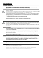
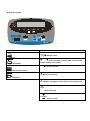
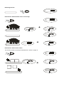
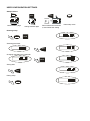
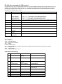
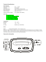
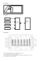
Model PS3000 with SBI-100 Indicator Operation Manual Safety and Warnings Installation and service THE EQUIPMENT CONTAINS NO USER SERVICEABLE COMPONENTS. Installation and maintenance of the equipment must only be carried out by trained and authorised personnel. Electrical installation The mains lead must be connected to a supply outlet with a protective earth contact. The electrical supply at the socket outlet must provide over current protection of an appropriate rating. For your protection all mains (110V or 230V) equipment used out of doors or in wet or damp conditions should be supplied from a correctly fused source and protected by an approved ground fault protection device (RCD, GFCI etc.) IF IN DOUBT SEEK ADVICE FROM A QUALIFIED ELECTRICIAN. Pluggable equipment must be installed near a easily accessible socket outlet. Routine maintenance To avoid the possibility of electric shock or damage to the machine, always switch off the machine and isolate from the power supply before carrying out any routine maintenance. To avoid the risk of the machine falling, where applicable, ensure that it is placed securely on a flat and level surface. Cleaning the machine The outside of standard products may be wiped down with a clean cloth, moistened with water containing a small amount of mild detergent. Harsh abrasives, solvents, scouring cleaners and alkaline cleaning solutions, such as washing soda, should not be used especially on the display windows. Under no circumstances should you attempt to wipe the inside of the machine. Do not spray any liquid directly onto the display windows. If you are using a proprietary cleaning fluid ensure you spray the cloth and not the display. Training Do not attempt to carry out any procedure on a machine unless you have received the appropriate training or read the Instruction Manual. To avoid the risk of RSI(repetitive Strain Injury) it is important to ensure that the machine is placed on a surface which is ergonomically satisfactory to the user. It is recommended that frequent breaks are taken during prolonged use. Sharp Objects Do not use sharp object (screw drivers, long fingernails, etc. to operate the keys. EMC compliance The following may be applicable to your machine. WARNING: This is a class A product. In a domestic environment this product may cause radio interference in which case the user may be required to take adequate measures. Display and Keypad NET Zero 0 kg Hold lb Low Batt - Max d= On/Off Zero AC CH + T kg/lb Tare Units Hold Print SBI 100 Function Keys Annunicators T Zero 0 Tare Weight is zero Tare lb kg On/Off Zero On/Off/Zero kg/lb Unit of measure (Flashing LED means that the weight reading is not stable.) NET Tare is activated Units Unit of measurement Hold Print CH Battery is charging. Hold/Print AC Adapter is plugged in, the indicator is receiving power. Hold Hold is activated Low Batt - + Battery is low. Manual symbols Multiple Key Press Long key press Short Key Press Scale Operation Turning On and Zeroing the Scale ZERO On/Off 0 Zero Turning off the scale On/Off Zero Selecting Unit of Measure Units kg → lb kg Using the Tare 1. NET 2. Tare NET 3. NET 4. lb Removing the Tare On/Off ZERO 0 Zero Hold function with automatic zero on next weigh. 1. Hold Print Hold 2. 3. 4. Hold Hold function with manual release. This function needs to be setup in Parameter P3.1 shown on page 10 1. 2. 3. Hold Print Hold Removing Hold Hold Print Hold Print Function For communications to a printer or PC, the indicator has to be setup in the following parameters P2, P4, P5 and P6. 1. 2. 3. Print Hold Print Gross: 45.00kg Tare: 1.35kg Net: 43.65kg USER CONFIGURATION SETTINGS Setup Controls Hold Print On/Off Tare Units Zero H kg H Moves flashing digit Change flashed digits H kg Saves data and move down to next Parameter setting . Entering setup On/Off Zero Units + Selecting parameter Tare Changing data within the parameter Units Saving data Tare Exiting setup ZERO 0 On/Off Zero Exits setup mode User Configuration Settings Parameter P1.xy P2.x Setting Auto shutoff timer in minutes Set up time for the auto off function. (00 = 0ff, 01-15 = time in minutes) Hold and print key functionality Setup button function 0 = Press button once to activate hold 1= Press button once to print 2= Press button to print/Press and hold button to activate hold. Hold Function Settings 0= No hold function active. Default settings in bold P1.00 P1.01 – P1.15, P1.5 = 5 minutes P2.0= Hold P2.1= Print; P2.2= Print & Hold, 1= Averaging hold with manual push button release. The weight reading will be held on the display until a higher weight is applied, this will automatically release the held weight and re-hold it at the new higher weight reading. P3.xy P3.0 P3.1 P3.2 2= Averaging hold with automatic release and re-hold. As above but The weight reading will be held on the display until P3.3 to 50 the platform is empted and the next weight reading over 10divisions is applied. 3-50= Selectable hold window from +/- 3 to 50 divisions Will hold display reading once stable within a selectable weight range, to release the hold button must be represses.. RS232 – Serial Interface Settings for serial interface 0= No RS232 output 1= Print displayed data once stable when print key is pressed; P4.x P4.0 2= Print gross, tare and net weight once stable when print key is P4.1 pressed P4.2 P4.3 3= Continuously output gross weight P4.4 P4.5 4= Continuously output gross, tare and net weight P4.6 P4.7 5= Print displayed data once stable one time only. 6= Print gross, tare and net weight once stable, one time only. 7= Bidirectional - RS232, SBI protocol RS232 Baud rate P5.x P6.x RS232 Data format 0 = 8 bits, no parity, 1 start bit, 1 stop bit 1 = 7 bits, 1 even, 1 start bit , 1 stop bit 2 = 7 bits, 1 odd, 1 start bit, 1 stop bit P5.0= 1200 P5.3= 9600 P5.1= 2400 P5.4= 19200 P5.2= 4800 P6. 0 P6. 1 P6. 2 SERVICE CONFIGURATIONS ONLY P7-P19 .x Any adjustment to these settings could seriously affect the indicators performance. Seek advice from a service engineer before changing. RS-232 data commands for SBI protocol The RS232 can be set so a bidirectional connection can be established between the indicator and the host. To establish this connection set parameter P4 to 7, and configure setting P5 (baud) and P6 (parity) to host device. Commands can then be sent from the host to the indicator using the following commands (ensure the letters entered are in CAPS) (<CR> - Enter) Command W<CR> Action Takes a reading Response S<CR> Over capacity Under capacity Zero point error Reading (kg or lb) Prints Status Bytes <LF>^^^^^^^^^u1u2<CR><LF>H1H2H3<CR><ETX> <LF>_______u1u2<CR><LF>H1H2H3<CR><ETX> <LF>----------u1u2<CR><LF>H1H2H3<CR><ETX> <LF><p>w1w2w3w4w5w6<dp>w7u1u2<CR><LF>H1H2H3<CR><ETX> <LF>H1H2H3<CR><ETX> Z<CR> Zeros the scale <LF>H1H2H3<CR><ETX> T<CR> Sets up a tare <LF>H1H2H3<CR><ETX> U<CR> Changes the units <LF>u1u2<CR><LF>H1H2H3<CR><ETX> L<CR> Activates the hold function Switches off the scale Unrecognised command <LF>H1H2H3<CR><ETX> X<CR> ? Indicator switches off. <LF>?<CR><ETX> Key Symbols <LF> Line feed <CR> Carriage Return <ETX> End of text character <SP> Space H1H2H3 3 status bytes <p> Polarity character including minus sign for negative weigh and a space character for positive. W1-W7 Weight data <dp> Decimal point U1U2: Unit measure, kg, lb or oz Output Status Bit Meaning: Bit 0 Byte 1 0=Stable Byte 2 0=Not Under Capacity Byte 3 00=Not defined 1=Unstable 1=Under Capacity 01=Normal working mode 0=Not at zero point 1=At zero point 0=Not over capacity 1=Over capacity 10=Hold working mode 2 Always 0 Always 0 0=Gross Weight 1=Net Weight 3 Always 0 Always 0 4 5 0=eprom OK 1=eprom error Always 1 Always 1 Always 1 Always 1 Always 1 Always 1 6 7 Always 0 Parity Always 1 Parity Always 0 Parity 1 11=Not defined Other RS-232 Output Strings Example: xxxxx0.18lb P4-1 = Output Displayed data @ print key : Format: <LF>< reading, minus, decimal point, weight unit><CR><EXT> P4-2 = Output Gross, Tare, Net @ print key Format: <LF><Gross: reading, minus, decimal point, unit><CR><EXT> <LF> <Tare: reading, decimal point, unit><CR><EXT> <LF> <Net: reading, minus, decimal point, unit><CR><EXT> Example: Gross:xxxxx0.36lb Tare:xxxxxx0.18lb Net:xxxxxxx0.18lb RS232 serial interface wiring Pin 2. 3. 5. DE-9 Female Scale Name Direction TXD Out RXD In SG - Pin 2. 3. 5. DE-9 Male Host Name Direction RXD In TXD Out Ground - Pins 1, 4, 6, 7, 8, 9 not used Load cell cable interface wiring 1 3 1. Red Excitation+ 2 1 RED 22.RED Black Excitation3 RED Green Signal43.RED 4 4. White Signal+ Scale calibration Calibration Configuration Settings – The scale is configured from the factory to match the specified settings for each unit, as defined by the product specifications and sales brochure. Modification of the setting can be accomplished by altering user configuration settings P7-P10. Caution: Calibration and/or configuration of calibration settings of your scale should be accomplished by a trained service technician using certified weights to ensure proper operation and accuracy. Calibration is not covered under warranty. Setup Controls Hold Print kg On/Off Tare Units Zero H H Moves flashing digit Change flashed digits kg H Saves data and move down to next Parameter setting . Exits setup mode Config Menu P7 Avail. Settings 00-31 Default Definition Detailed Setting 10 Displayed Resolution 0,1,2 0-5 0 0 Division Increment Decimal Position 0, 1 1 Calibration weight (00) = 500 (08) = 2400 (15) = 7000 (01 )= 600 (09) = 2500 (16) = 7500 (02 )= 750 (10 )= 3000 (17) = 8000 (03 )= 800 (11) = 3500 (18) = 10,000 (04) =1000 (12 )= 4000 (19) = 12,000 (05 )=1200 (13) = 5000 (20) = 15,000 (06) =1500 (14) = 6000 (21-31) = N/A (07) = 2000 0=1;1=2;2=5 0 = 123456 ; 1 = 12345.6; 2 = 1234.56 ; 3 = 123.456 ; 4 = 12.3456 ; 5 = 1.23456 0 = KG ; 1 = LB P8 P9 P10 You may choose to configure your scale for a higher resolution. The factory does not recommend increasing the resolution above 3,000 divisions for a stable weight reading. Certain environments may cause the scale to be unstable at factory settings, reduce the # of division settings to increase your stability. Calibration Settings when configuring as an SBI 100 Indicator to a remote base If you are configuring the SBI 100 Indicator to be used with a scale other than the PS3000 base, you will need to alter the configuration setting in P7- P10 manually. In order to configure the Indicator follow the steps defined below: 1. Determine the full capacity of your scale. Example: 3000 pounds 2. Determine the displayed division of your scale. Example: 1 pounds (this is your P8, P9, and P10 setting) 3. Divide the capacity by the displayed division to determine the displayed resolution of your scale. Example: 3000/1 = 3000 (this is your P7 setting) You are now able to configure P7 – P10 as follows. Primary Capacity 3000 x 1 lbs Displayed Resolution 3000 Units Selectable Capacity 1500 x 0.5 kg P7 10 P8 0 P9 0 P10 1 P7 10 P8 2 P9 1 P10 0 If primary capacity is 1500 x 0.5 kg, configure P7-P10 as follows:. Primary Capacity 1500 x 0.5 kg Displayed Resolution 3000 Units Selectable Capacity 3000 x1 lbs Calibration Menu Hold Print kg On/Off Tare Units Zero H H Moves flashing digit Change flashed digits kg H Saves data and move down to next Parameter setting . Exits setup mode Calibration can be done with 10% to 100% of requested load and can be calibrated with 1 or 2 calibration points On/Off 1. Zero Tare + Tare 2. Tare 3. 4. Enter in calibration weight from 5% to 100% full capacity 25%-100% 50.00 kg/lb Hold Print Units Tare 5. Single point calibration, enter the same weight in again and move to number 7 For 2 point calibration enter in the second calibration weight between 10% 100% full capacity. Tare 6. 25%-100% 100.00 kg/lb Hold Print Units Tare Tare 7 8. ZERO 0 Tare 9. Service Configuration Settings The scale is configured from the factory to match the specified settings for each unit, as defined by the product specifications and sales brochure. Modification of the setting can be accomplished by altering user configuration settings P11-P19. Caution: Configuration of the settings of your scale should be accomplished by a trained service technician to ensure proper operation and accuracy. Configuration is not covered under warranty. Setup Controls Hold Print On/Off Tare Units Zero H kg H Moves flashing digit Change flashed digits Config Menu P11 Avail. Settings 0,1,2 P12 0-7 7 P13 00 - 15 03 P14 0, 1, 2 0 P15 0, 1, 2 1 P16 0-8 P17 P18 P19 kg H Saves data and move down to next Parameter setting . Exits setup mode Default Definition Detailed Setting 2 Units key configuration Power On zero range Zero button range 0 = KG only ; 1 = LB only ; 2 = units key active KG and LB 0 = +/- 1% ; 1 = +/- 2% ; 2 = +/- 5% ; 3 = +/- 10% ; 4 = +/- 20% ; 5 = +/- 50% ; 6 = +/- 100% ; 7 = no limitation (00) = +/- 1% (06) = +/- 20% (12) = + 5% (01 )= +/- 2% (07) = +/-no limit (13) = + 10% (02 )= +/- 3% (08 )= + 1% (14) = + 20% (03 )= +/- 4% (09) = + 2% (25) = + no limit (04) =+/- 5% (10 )= + 3% (05 )= +/- 10% (11) = + 4% 0 = current weight ; 1 = calibration zero ; 2 = power off zero point 6 Signal within power on zero point range Signal not within power on zero point Zero tracking 0-3 0-9 3 9 Data Filter Weight stability 0-9 1 Overload range Full scale 0 = current weight ; 1 = calibration zero ; 2 = power off ----zero point ; 3 = continuously display “0 “ 0 = 0d AZT off ; 1 = +/- 0.25d, 2 = +/- 0.5d ; 3 = +/- 1d; 4= +/- 1.5d ;5= +/- 2d ;6 = +/- 3d; 7= +/- 4d; 8 = +/- 5d 0 = very weak; 1 = weak; 2 = standard; 3 = strong 0 = +/- 0.5d ; 1= +/- 1d; 2= +/- 1.5d ; 3= +/- 2d; 4= +/3d ;5= +/- 4d ;6 = +/- 5d; 7= +/- 6d; 8 = +/- 7d; 9 = +/8d 0 = 0% ; 1 = +9d ; 2 = 101% ; 3 = 102% ; 4 = 405% ; 5 = 110% ; 6 = 120% ; 7 = 150%; 8 = 200%; 9 = no limitation Technical Specifications Scale Indicator Input signal range: 0mV ~ +30mV Sensitivity: >0.2uV/grad Internal Resolution: Approximately 520,000 counts Display Resolution: Can be selected between 500-100,000 System Linearity: Within 0.01% of FS Loadcell excitation Voltage: +5 VDC (MAX current: 85mA) Load cells: 1. 2. 3. 4. 5. quantity: 4 pcs each one capacity: 1000kg sensitivity: 2.5±0.5mV/V input resistant: 400±10Ω output resistant: 352±2Ω Temperature Storage: 5oC - 35 oC 10oC - 70 oC Humidity: ≤95%RH (no condensation) Operation: Power Battery: 6V4AH lead acid battery, 30 hrs continuous use When the voltage of battery is below 5.7V, the “Low Bat”annunciator will be lighted, plug in AC adapter to charge the battery. When ”Lo.bAt” and actual weight is displayed alternately, this indicates the voltage of battery is below 5.5V and the scale will be turned off in two minutes automatically. Connection Information Power/Adapter Socket Loadcell socket RS232 Power Supply 6V DC - 500mA + 230V - 50Hz - Connecting: Loadcell1 Loadcell2 Junction box SBI100 Indicator Loadcell3 Loadcell4 Junction Box: 1. W1-W4: to adjust 4 corner error, W5-W6: not used 2. W0: to adjust scale’s zero-point balance 3. 1#-4# connector: connect to loadcell1---loadcell4, 5#-6#connector: not used 4. 0#connector: connect to indicator 5. Connector pins: SH---shield wire EXC+ --- Excitation+ EXC- --- ExcitationSIG+ --- Signal + SIG- --- Signal SEN+ --- Sense+ , connect to EXC+ SEN- --- Sense- , connect to EXCPlatform material: 1. 4mm chequered plate Wire the cable attached to the indicator as shown 1 3 2 4 1. Red Excitation+ 1 RED 22.RED Black Excitation3 RED Green Signal43.RED 4. White Signal+ Error Messages Error Message Definition Required Solution/Troubleshooting 0¯ ¯ ¯ ¯: Weight above range for calibrated zero point. Remove load before zeroing Or Recalibrate the scale. Put platform on scale(if it removed) Or Recalibrate the scale. Recalibrate the scale. Weight below range for calibrated zero point. 0_____: Indicates an under range condition _____: Capacity exceeded Remove the load or a scale with a larger capacity is required. CAL-Er: Lo.bAt: Calibration error Low Battery EEP.E0 EEP.E1 EEPROM can’t be accessed Configuration settings have changed and not been stored Configuration settings exceed scale’s normal range Restart calibration Recharge the battery. Upon initial use, it is recommended to charge battery for more than 8 hours prior to use. Replace S100 Indicator Reconfigure and Calibrate the scale to store settings Reconfigure and Calibrate the scale to store settings ¯ ¯ ¯ ¯: EEP.E2 Declarations of Compliance United States This equipment has been tested and found to comply with the limits for a class A digital device, pursuant to Part 15 of the FCC Rules. These limits are designed to provide reasonable protection against harmful interference when the equipment is operated in a commercial environment. This equipment generates, uses, and can radiate radio frequency energy and, if not installed and used in accordance with the instruction manual, may cause harmful interference to radio communications. Operation of this equipment in a residential area is likely to cause harmful interference in which case the user will be required to correct the interference at his own expense. Canada This digital apparatus does not exceed the Class A limits for the radio noise emissions from digital apparatus set out in the Radio Interference Regulations of the Canadian Department of Communications. Le présent appareil numérique n’émet pas de bruits radioélectriques dépassant les limites applicables aux appareils numériques de la Classe A prescrites dans le Règlement sur le brouillage radioélectrique edicté par le ministère des Communications du Canada. ©Avery Weigh-Tronix, LLC. All rights reserved. The information contained herein is the property of Avery Weigh-Tronix and is supplied without liability for errors or omissions. No part may be reproduced or used except as authorised by contract or other written permission. The copyright and the foregoing restriction on reproduction and use extend to all media in which the information may be embodied. Salter Brecknell is a trading name of Avery Weigh-Tronix LLC Contact Information & Technical Support USA UK and Europe Salter Brecknell Weighing Products USA 1000 Armstrong Drive Fairmont MN 56031 Toll Free: 800-637-0529 Phone: 507-238-8702 Fax: 507-238-8271 email:[email protected] www.salterbrecknell.com Salter Brecknell Weighing P.O. Box 9533, Smethwick, West Midlands, B66 2TE. United Kingdom. Tel: +44 (0) 870 444 6132 Fax: +44 (0) 870 010 2241 email:[email protected] www.salterbrecknell.co.uk Rev 5/12/10