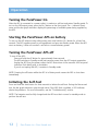
1
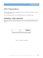
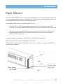
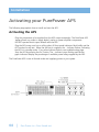
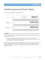
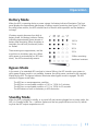
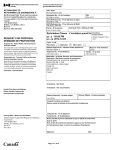
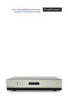
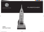
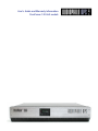
User’s Guide and Warranty Information
PurePower 120 Volt models
Contents
Table of Contents
About the PurePower APS
2
Safety Warnings
3
Installation
Inspecting the Equipment
4
PurePower Preparation
5
Activating Up Your PurePower
8
Operation
12
PurePower Maintenance
13
Specifications
14
Troubleshooting
16
Service and Support
17
Audiophile Power Supply • www.audiophileaps.com
| 01
About the Audiophile APS
The PurePower Audio Power Supply
The Audiophile Audio Power Supply (APS) provides pure regenerated power for your sensitive
home theater and audio equipment. This is accomplished through our double conversion technology. We convert the incoming AC power to produce a clean DC supply, then recreate a new, 60
Hz, 120 volt AC wave form from the DC. We make sure that your system gets the power it was
designed for and your amplifiers get the current they need for top performance.
The APS also protects from power disturbances including power sags, power surges, overvoltages, line noise, undervoltages, frequency variations, switching transients and harmonic distortion. Power disturbances have the potential to damage sensitive hardware causing expensive
repairs with either catastrophic failures or degradation over time through chronic overheating.
With the APS you can safely eliminate the effects of power disturbances and guard the integrity
of your equipment.
In addition to pure power, the Audiophile APS provides you with something unique in audio
power regenerators - protection against power outage. The Audiophile APS maintains full wattage
output even when the power fails completely.
Providing outstanding performance and reliability, the
PurePower’s unique benefits include the following:
• True double conversion AC regeneration design with pure sine wave output. The APS filters
and regulates incoming AC power, creates a DC source, then regenerates new pure AC and
provides monitored, consistent power to your components.
• The APS improves amplifier performance by ensuring full wattage and improves signal com
ponent output quality by removing noise and distortion.
• The PurePower APS design allows any of our 6 available high quality, full contact receptacles
to supply digital, analog or amplifier components.
• Hours of extended viewing or listening time with optional APS PowerPack Modules
during outages.
• Optional Line surge protection guards against spikes and surges on coax or RJ11 lines.
• Start on battery capabilities allows you to power up the APS even if utility power is not
available.
02 |
Pure Power in > Pure Sound out
Safety Warnings
Safety Warnings
Read the following precautions before you install the APS.
IMPORTANT SAFTEY INSTRUCTIONS - SAVE THESE INSTRUCTIONS.
This manual contains important instructions that you should follow during installation and maintenance of the APS and batteries. Please read all instructions before operating the equipment and
save this manual for future reference.
DANGER
This APS contains LETHAL VOLTAGES. All repairs and service should be preformed by AUTHORIZED
SERVICE PERSONNEL ONLY. There are NO USER SERVICEABLE PARTS inside the APS.
WARNING
This APS contains its own energy source. The output receptacles may carry live voltage even when
the APS is not plugged in.
Under normal operating conditions, do not remove or unplug the input cord when the APS is
turned on. This removes the safety ground from the APS and the equipment connected to the
APS.
To reduce the risk of fire or electric shock, install this APS in a temperature and humidity controlled, indoor environment, free of conductive contaminants. Ambient temperature must not
exceed 32°C (90°F). Do not operate near water or excessive humidity (95% max).
To comply with international standards and wiring regulations, the total equipment connected
to the output of this APS must not have an earth leakage current greater than 1.5 milliamperes.
CAUTION
Batteries can present a risk of electrical shock or burn from high short-circuit current. Observe
proper precautions. Servicing should be preformed by qualified service personnel knowledgeable
of batteries and required precautions.
Proper disposal of batteries is required. Refer to your local codes for disposal requirements.
Never dispose of batteries in a fire. Batteries may explode when exposed to flame.
Audiophile Power Supply • www.audiophileaps.com
| 03
Installation
Inspecting the Equipment
Before installation, please check to ensure that your PurePower APS package is complete and
undamaged. If any deficiencies are discovered, please contact your PurePower Dealer.
Shipping damage
If any equipment has been damaged during shipment, keep the shipping cartons and packing
materials for the carrier or place of purchase and file a claim for shipping damage. If you discover
damage after acceptance, file a claim for concealed damage.
To file a claim for shipping damage or concealed damage:
1) File with the carrier within 15 days of receipt of the equipment
2) Send a copy of the damage claim within 15 days to your Audiophile APS dealer.
04 |
Pure Power in > Pure Sound out
Installation
APS Preparation
The APS is designed for flexible configurations and can be rack mounted or placed on a shelf or
as a standalone cabinet.
If you are installing the APS in a rack, follow the instruction in “Rack-Mount Setup”.
Standalone / shelf component
When you position the APS horizontally on a shelf or in a non-rack style AV equipment stand or
enclosure, ensure there is sufficient clearance for airflow through the grilles at front and rear of
the unit.
Figure 1. Horizontal Cabinet Setup
Audiophile Power Supply • www.audiophileaps.com
| 05
Installation
06 |
Pure Power in > Pure Sound out
Installation
Rack-Mount
The APS can be installed in 19 or 23-inch racks and needs only 2U of rack space. Mounting rails
or a rack shelf are required for your Audiophile APS. If rails are not already installed in your rack
or included with your APS, contact your PurePower dealer.
Use the following procedure to install the APS in a rack:
· Place the APS on a flat, stable surface with the front of the APS facing toward you.
· Attach the mounting handles to the bracket with the screws provided in the accessory kit.
· Remove the screws attaching the front bezel from one side of the unit. Align the rack
mounting brackets with the screw holes on the side of the APS and replace screws.
· Repeat for the opposite side.
If installing optional PowerPacks, repeat Steps 1 through 4 for each cabinet.
NOTE The PowerPacks must be installed BELOW the APS.
Slide the APS and any optional PowerPacks into the rack. Continue to “Installing the APS” to
complete the installation.
Audiophile Power Supply • www.audiophileaps.com
| 07
Installation
Activating your PurePower APS
The following steps explain how to install and start the APS.
Activating the APS
· Plug the components to be supplied into the APS output receptacles. The PurePower APS
design allows any outlet to supply digital, analog or power amplifier components.
· DO NOT operate electric space heaters with the APS.
· Plug the APS power cord into a utility outlet. All front panel indicators flash briefly and the
APS conducts a self-test. When the self-test is complete, the ~ indicator flashes, indicating
the APS is in standby mode. If any other indicator flashes, see troubleshooting page.
· Start the APS by pressing the On | button. The ~ indicator stops flashing and the bar
graph indicators display the percentage of available power being supplied by the APS.
The PurePower APS is now in Normal mode and supplying power to your system.
08 |
Pure Power in > Pure Sound out
Installation
Installing optional Power Packs
Modules must be installed before powering the APS.
CAUTION: A small amount of arcing may occur when connecting a PowerPack Module to the
APS. This is normal and will not harm you. Insert the connection cable into the APS battery connector quickly and firmly.
· Plug the first PowerPack cable into the battery connector on the APS rear panel
· If additional PowerPacks are to be installed, plug the cable of the second cabinet into the
battery connector on the previous Powerpack
NOTE: The batteries charge to 80% capacity in approximately 2 hours. However, it is recommended that the batteries charge for 24 hours after installation or long-term storage. The battery
charging process will occur during normal operation and will not interfere with the supply of
power from the APS.
Audiophile Power Supply • www.audiophileaps.com
| 09
Operation
Operation
The PurePower Front panel indicates the APS status through the LED indicators. Figure below
shows the APS front panel indicators and controls.
Figure 15. APS Front Panel
Normal Mode
During Normal mode, the ~ indicator illuminates and the front panel displays the percentage of
APS load capacity being used by your system. (see Figure). The APS monitors and provides power
to your system and charges the batteries as
needed.
The LEDs do not illuminate when the APS
load is less than approximately 10%. Each
LED represents a percentage of a full load
rating. If all of the bar graph indicators are
illuminated and the red overload indicator
flashes, power requirements exceed APS
capacity.
less than 10%
10 - 25 %
25 - 50 %
50 - 75 %
75 - 100 %
overloaded
10 |
Pure Power in > Pure Sound out
Operation
Battery Mode
When the APS is operating during a power outage, the battery indicator illuminates. The front
panel displays the approximate percentage of battery capacity remaining (see figure 17). When
the utility power returns, the APS switches back to Normal mode operation and the batteries
recharge.
If battery capacity becomes low while in
battery mode, the battery indicator flashes
indicating approximately three minutes of
battery time remaining. When shutdown is
imminent, the self test (checkmark) indicator flashes.
These warnings are approximate, and the
actual time to shutdown may vary. When
utility power is restored after an APS shut
down, the APS automatically restarts.
100 %
75 %
50 %
25 %
3 Mins. remaining
shutdown imminent
Bypass Mode
In the event of an extended APS overload or internal failure, the APS transfers your system to
utility power. Battery mode is not available, however the utility power continues to be passively
filtered by the APS. The bypass indicator illuminates when bypass mode is engaged. The APS
switches to Bypass mode when:
· The APS has an overtemperature condition.
· The APS has an overloaded condition of 101 to 110% for 2 minutes.
· The APS has an overloaded condition of 111 to 150% for 30 seconds.
· The APS detects a fault in the battery or APS electronics.
Standby Mode
When the APS is plugged in initially, or is turned off and remains plugged into a power outlet, the
APS is in Standby mode. The ~ indicator flashes and the bar graph indicators are not lit, indicating that the APS output receptacles are off.
Audiophile Power Supply • www.audiophileaps.com
| 11
Operation
Turning the PurePower On
After the APS is connected to a power outlet, it conducts a self-test and enters Standby mode. To
turn on the APSoutput power, press the On | button on the front panel. The ~ indicator illuminates and the bar graph indicators display the percentage of available power being supplied by
the APS.
Starting the PurePower APS on battery
To turn on the APS without using utility power, press and hold the On | button for a least four
seconds. The APS supplies power to your equipment and goes into Battery mode. When the APS
starts on battery, it does not conduct a self-test to conserve battery power.
Turning the PurePower APS off
To turn off the APS:
· Press and hold the off button for approximately three seconds.
· The APS switches to Standby mode and removes power from the APS output receptacles.
· Unplug the APS from the power outlet; the APS shuts down in five seconds. All front panel
indicators flash briefly prior to shutdown.
· If you do not unplug the APS, it remains in Standby mode.
NOTE: Pressing the off button while the APS is in Battery mode causes the APS to shut down
immediately.
Initiating the Self-Test
Press and hold the alert button for three seconds to initiate the self-test. During the five-second
test, the bar graph indicators cycle through twice. If the APS finds a problem, a LED indicates
where the problem is. For more information, see the “Troubleshooting” section.
NOTE: The batteries must be fully charged and the APS must be in normal or standby mode to
perform the self-test.
12 |
Pure Power in > Pure Sound out
APS Maintenance
PurePower Maintenance
PurePower APS and Battery Care
For the best preventive maintenance, keep the area around the APS clean and dust-free. If the
atmosphere is very dusty, clean the outside of the system with a vacuum cleaner. For full battery
life, keep the APS at an ambient temperature of 21° C (72° F).
Storing the APS and Batteries
If you store the APS for a long period, recharge the batteries every 12 months by plugging the
APS into a power outlet. The batteries charge to 80% capacity in approximately 2 hours.
However, it is recommended that the batteries charge for 24 hours after long-term storage.
When to Replace Batteries
When the battery indicator illuminates, the batteries may need replacing. Conduct a self-test. If
the battery indicator stays on, contact Audiophile or your Audiophile dealer to order new batteries. The average battery life is aproximately 5-7 years.
The PurePower APS will still provide full power conditioning and protection when the batteries
need replacement, but it will not be able to continue to operate during a power outage.
You may perform the battery replacement yourself by ordering an Audiophile battery replacement
kit. Full instructions are included with the kit and are also available on our web site.
Audiophile Power Supply • www.audiophileaps.com
| 13
Specifications
Specifications
This section provides the following specifications for the PurePower APS
· Electrical input and output
· Weights and dimensions
· Environmental and safety
· Battery
Model List
PurePower APS Model 500
PurePower APS Model 700
PurePower APS Model 1050
Watts
490
700
1050
Weight Lb. (kg)
34 (15)
34 (15)
50 (23)
Dimensions (HxWxD)
3.5 x 17 x 19.5”
3.5 x 17 x 19.5”
3.5 x 17 x 19.5”
Electrical Input
Nominal Voltage
Voltage Range
Frequency Range
Noise filtering
Input Connections
120V
80 – 144V
45-65Hz, 50/60 Hz auto-sensing
MOVs & line filter for normal & common mode noise
IEC-320 Input receptacle with supplied 6’ power cord
Electrical Outputs
Output Voltage
Voltage Regulation
Voltage Waveform
Output Receptacles
Energy Efficiency
14 |
120 VAC
Nominal output voltage ±2%
Normal mode: Sine wave; <3% THD with full PFC
(6) 5-15 R
89 - 92 % depending on load
Pure Power in > Pure Sound out
Specifications
Environmental and Safety
Operating Temperature
Optimal battery performance:
Storage Temperature
Transit Temperature
Relative Humidity
Operating Altitude
Transit Altitude
Audible Noise
Surge Suppression
Safety Conformance
Safety Markings
EMC (Class B)
0°C to 32°C (32°F to 90°F)
21°C (72°F)
0°C to 25°C (32°F to 77°F)
-25°C to 55°C (-13°F to 131°F)
5-90% noncondensing
Up to 3,000 meters above sea level
Up to 10,000 meters above sea level
Less than 20 dBA
ANSI C62.41 Category B (formerly IEEE 587)
UL 1778, UL 497A;
CAN/CSA C222.2, No. 107.1, 107.2
NOM-019-SCFI
UL CSA Entella
FCC Part 15, ICES-003, VCCI
Class B EMC Statement
FCC Part 15
Note: This equipment has been tested and found to comply with the limits for a class B digital
device, pursuant to part 15 to the FCC Rules. These limits are designed to provide reasonable protection against harmful interference in a residential installation. This equipment generates, uses
and can radiate radio frequency energy and, if not installed and used in accordance with the
instructions, may cause harmful interference to radio communications. However, there is no guarantee that interference will not occur in a particular installation. If this equipment does cause
harmful interference to radio or television reception, which can be determined by turning the
equipment off and on, the user is encouraged to try to correct the interference by one or more of
the following measures:
• Reorient or relocate the receiving antenna.
• Increase the separation between the equipment and the receiver.
• Connect the equipment into an outlet on a circuit different from that it which the
receiver is connected.
• Consult the dealer or and experienced radio/television technician for help.
ICES-003
This Class B Interference Causing Equipment meets all requirements of the Canadian Interference
Causing Equipment Regulations ICES-003
Audiophile Power Supply • www.audiophileaps.com
| 15
Troubleshooting
Troubleshooting your PurePower APS
This section contains troubleshooting information and an explanation of APS alarm conditions.
Condition
Possible Cause
Resolution
The normal mode indicator
is not on or APS won’t start
Power cord not connected
Wall outlet is faulty
Check connections
Have outlet checked and repaired
Normal mode indicator
flashing, no power output
APS is in standby mode
Press the on button to switch to normal
mode
Battery indicator is lit
Utility power failure
APS is not connected to wall
none
Check Input power cable
Bypass indicator is lit
APS in bypass mode
Your components have been transferred
to utility power. Power filtering an
surge suppression are active. Check
other fault indicators for cause.
Bypass indicator flashing
Bypass mode not available
Input power not within acceptable
standards, APS will continue to supply
your components.
Battery indicator flashing
Battery fully discharged
Allow batteries to charge for 24 hours
then hold alarm reset button for 3 secs.
for self test.
Replace the batteries or contact your
dealer.
Battery failure
Ground fault indicator flashing
No ground wire or line
or neutral reversed in wall
Have the outlet wiring corrected
Overtemp indicator flashing
Internal temp too high
Turn off and unplug APS, allow
to cool. check for blocked vents
and that airflow is not restricted. If
problem persists, contact your dealer.
Overload indicator flashing,
APS turns off output
Power demand exceeds
APS overload capacity*
Turn off and unplug APS. Wait 5
seconds, restart APS. If problem
persists, remove components from
APS until wattage is within APS rating.
Some amplifiers have extremely high
power draws excessive voltage*
on startup. A higher wattage APS model
may be required.
Amplifier startup demands
* The Audiophile APS is capable of supporting up to 110% of its rated capacity for 2 minutes and up to 150% of its
rated capacity for 30 seconds.
16 |
Pure Power in > Pure Sound out
Service & Support
Service And Support
For setup and support for your PurePower APS, please contact your authorized
PurePower Dealer.
For warranty service, please contact your authorized dealer or Audiophile APS. All PurePower APS
models have a two year swap out warranty for original registered owners. If we are unable to
solve a problem with your APS over the phone, we’ll send you a replacement unit. Just return the
original in the same packaging with the supplied shipping documentation.
For technical support and warranty service, Please contact Audiophile APS via:
email: [email protected] | phone at 519.624.9735 | fax at 519.624.9592
Audiophile Power Supply • www.audiophileaps.com
| 17
Pure Power in > Pure Sound out • www.audiophileaps.com