1
User's Manual
C 2004 Thermaltake Technology Co.,Ltd. All Rights Reserved.
www.thermaltake.com
Contents
Chapter l Product Introduction
1.1 Specification
1
Chapter 2 Case Mechanical Operation
2.1 How to open the side panel
3
2.2 Lock operation
4
2.3 Installing 5.25" device
5
2.4 PCI slot tool-free function operation
7
2.5 Installing 3.5" HDD
8
2.6 Installing 3.5" device
9
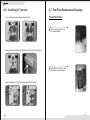
2.7 Fan Filter removal and cleaning
10
Chapter 3 Motherboard & Leads Installation
3.1 Motherboard installation
11
3.2 Case LED connections
12
3.3 USB2.0 & IEEE1394 Firewire connection
13
3.4 Ear & MIC connections
14
3.5 Case open alarm function
14
Chapter 4 Other
4.1 Silent Purepower
TM
power supply(optional)
15
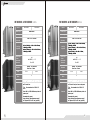
VB1000SNS & VB1000BNS >>>
Model
VB1000BNS
Model
VB1000SWS
VB1000BWS
Case Type
Middle Tower
Case Type
Middle Tower
Net Weight
9.6 kg
Net Weight
9.4 kg
495 x 210 x 478 mm
Dimension
(H*W*D)
495 x 210 x 478 mm
Dimension
(H*W*D)
Cooling
System
Front (intake) : 120 x 120 x25 mm,
1400rpm, 21dBA
Rear (Exhaust) : 120 x 120 x25 mm,
1400rpm, 21dBA
Cooling
System
Front (intake) : 120 x 120 x25 mm,
1400rpm, 21dBA
Rear (Exhaust) : 120 x 120 x25 mm,
1400rpm, 21dBA
Side (intake) : 90 x 90 x 25mm,
1800rpm, 21dBA
Drive Bays
-Front
Accessible
-Internal
11
4 x 5.25
5.25" , 2 x 3.5"
5 x 3.5"
3.5
Drive Bays
-Front
Accessible
-Internal
11
4 x 5.25
5.25" , 2 x 3.5"
5 x 3.5"
3.5
Material
Chassis : 0.8 mm SECC
Front Door : Plastic
Material
Chassis : 0.8 mm SECC
Front Door : Plastic
color
Expansion
Slots
Motherboards
Features
1
VB1000SNS
VB1000SWS & VB1000BWS >>>
Silver
Black
color
Silver
Black
7
Expansion
Slots
7
Micro ATX (9.6"
(9.6 x 9.6"
9.6 ), ATX ( 12"
12 x 9.6"
9.6 )
Motherboards
Micro ATX (9.6"
(9.6 x 9.6"
9.6 ), ATX ( 12"
12 x 9.6"
9.6 )
§ High efficiency ventilation: Dual 12cm silent
fan in front & rear.
rear
§ High efficiency ventilation: Dual 12cm silent
fan in front & rear, 9cm fan on side panel.
§ Tool - Free installation for 5.25"
5.25 & 3.5"
3.5
device.
§ Tool - Free installation for 5.25"
5.25 & 3.5"
3.5
device.
§ Dual USB 2.0, IEEE 1394Firewire, Audio &
Speaker ports
Features
§ Dual USB 2.0, IEEE 1394Firewire, Audio &
Speaker ports
§ Retractable foot stand.
§ Retractable foot stand.
§ Highly flexible "Silent Purepower supply "
unit supports PS/II for PC case (optional)
§ Highly flexible "Silent Purepower supply "
unit supports PS/II for PC case (optional)
2
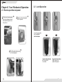
Chapter2 Case Mechanical Operation
2.2 Lock Operation
2.1 How to open the side panel
1 To find out the side panel
key from the back side of
the case then open it as
the picture..
2 Make sure the side panel
lock is opened.
Insert the provided
key and turn it
anticlockwise.
Unlock
3 Push the button then swing
out the side panel.
Turn it anticlockwise
90 to open the
front door.
O
3
Turn it anticlockwise
180 to open the
whole front panel.
O
4
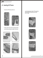
2.3 Installing 5.25" Device
ΠUnscrew the 5.25" drive bay metal cover.
Ž Insert the railed device into the 5.25" drive bay then
slide it along the fixed-positioning rack inside
the 5.25" cage.
• To find out the drive bay rail from enclosed box.Please
note the difference between the right(R) & left(L) rails.
L
5
6
2.4 PCI slot tool-free function operation
2.5 Installing 3.5 HDD
u Turn lock device counter-clockwise to unlock.
ΠOpen the plastic clip then take off the PCI bracket as follow.
v Remove lock device.
w Insert HDD and place on lock device.
Turn lock device clockwise to secure the HDD.
7
8
2.6 Installing 3.5" device
u Turn lock device counter-clockwise to unlock.
2.7 Fan Filter Removal and Cleaning
Front-Fan Filters
1 Firstly, open up the whole
front panel & door.
v Remove lock device and insert drive from the front of the chassis.
2 Take off the Fan Grille, then
the filter can be removed.
w Insert lock device and turn clockwise to secure the drive.
9
10
Chapter3 Motherboard & Leads
Installation
3.1 Motherboard Installation
Each motherboard has different standoff layout. It is highly
suggested that you refer to your motherboard's manual when
installing motherboard into the Case. The cases are applicable with
Standard ATX, Micro ATX, Dual processor Form Factor motherboards.
Your motherboard may require a special I/O Panel, which should be
included with your motherboard.
Placement Direction:
When installing the motherboard, make sure you follow the direction
provided by your motherboard manufacturer. On most standard
motherboards, the edge with external ports goes to the rear part of the
chassis. It is highly recommended that you install CPU, heat sink and
modular components before fixing the motherboard inside the chassis.
3.2 Case LED connections
On the front of the case, you can find some LEDs and switch leads
(POWER SW*1, POWER LED*1, H.D.D. LED*1, RESET SW*1
, SPEAKER*1).
Please consult user manual of your motherboard manufacturer, then
connect these leads to the panel header on the motherboard. These
leads are usually labeled; if not, please trace them back to the case
front to find out their source.
- POWER LED connects to your M/B at the PLED
- POWER SW connects to the PWR connector on the motherboard.
- H.D.D LED connects to the 2-pin labeled HDD LED connector.
- RESET SW connects to the RSW connector on the motherboard,
- SPEAKER connector: find out the 4-pin labeled SPEAKER on the
M/B then connect it.
= the locations of
the screw holes. Note
these locations and
place included
standoffs on the chassis
first.
This side towards
the rear of the
chassis
Above illustration is a sample of what
the motherboard's layout. For more
detail screw hole placement, please
refer to your motherboard manual.
11
12
3.3 USB2.0 & IEEE1394 Firewire connection
3.4 Ear & MIC connections
USB connection
Please consult your motherboard manual to find out
the section of "front panel audio connector".
Please consult your motherboard manual to find
out the section of "USB connection".
Ear & Mic connection
M/B layout (Ex: ASUS)
USB2.0 connection
Red
Case layout
1
LINE_OUT R
EAR R
1
USB+5V
VCC 1
Red
2
LINE_IN R
Return R
White
2
LDM1
DATA-1
White
LDP1
DATA+1
Green
LINE_OUT L
Green
3
3
EAR L
4
LINE_IN L
Return L
Yellow
M/B layout (Ex: ASUS)
USB 1
GND
GND 1
Black
5
NC
SHIELD 1
Black
5
MIC
MIC IN
Orange
6
USB+5V
VCC 2
Red
6
MIC PWR
MIC VCC or MICBIAS
Blue
7
LDM2
DATA-2
White
7
Ground
Ground
Black
8
LDP2
GND
--
DATA+2
Green
GND 2
Black
SHIELD 2
Black
4
9
10
USB 2
IEEE1394 Firewire connection
3.5 Case open alarm function
Please consult your motherboard manual to find
out the section of "IEEE1394 Firewire connection".
1 To find out the cable with 2pin
1394 Firewire connection
connector ("Micro SW") from the
rear of inside the chassis.
Case layout
M/B layout (Ex: ASUS)
13
Case layout
1
+12V
VP
White
2
Ground
VG
Black
3
TPB-
TPB- or TPB*
Red
4
TPB+
TPB+ or TPB
Green
5
TPA-
TPA- or TPA*
Orange
6
TPA+
TPA+ or TPA
Blue
7
Ground
Ground
Black
White Wire
2 To find out the position of Chassis
Alarm on your motherboard.
(please consult your motherboard
manual)
Black Wire
14
Chapter4 Other
TM
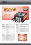
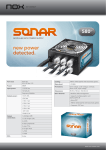
4.1 Purepower power supply (optional)
The Thermaltake Silent TM Purepower specification meets Intel
Pentium 4 and AMD K7; it offers plenty of functions, which mainly
include:
1.Automatic Fan Speed Control: The Silent Purepower TM power
supply can detect the inside heat and automatically adjust the fan
speed to provide adequate airflow.
2.Ultra Silent:Ball bearing fans with high reliability and super low
acoustic noise under all load condition.
The functions can assure the Silent Purepower TM meet the balance in
noise control and heat exhausted. The Silent PurepowerTM provides
complete protection function as follow:
1.Over thermal protection at 100 oC-105 oC
2.Short circuit protection on all output.
3.Over voltage protection / Under voltage protection.
4.Over current protection.
Besides, Thermaltake enables the quality assurance of the Silent
Purepower TM: 100% Hi-POT and ATE Function Test, 100% Burn-In and
AC Input cycled on/off under high temperature condition. Furthermore,
it has been approved by UL, CSA, TUV, VDE, NODIC, CB, FCC, CE,
CNS.
There are three main products of Thermaltake PSU, it is divided into
standard, VR and specialty power supply unit. Please refer to
http://www.thermaltake.com/purepower/main.htm
15
16