1
Agilent 4287A RF LCR Meter
Programming Manual
Seventh Edition
FIRMWARE REVISIONS/SERIAL NUMBERS
This manual applies directly to instruments that have the firmware revision 1.3x
and serial number prefix JP1KG. For additional important information
on firmware revisions and serial numbers, see Appendix A.
Agilent Part No. 04287-90071
May 2003
Printed in Japan
Notices
The information contained in this document is subject to change without notice.
This document contains proprietary information that is protected by copyright. All rights
are reserved. No part of this document may be photocopied, reproduced, or translated to
another language without the prior written consent of Agilent Technologies.
Agilent Technologies Japan, Ltd.
Component Test PGU-Kobe
1-3-2 Murotani, Nishi-ku, Kobe, Hyogo, 651-2241 Japan
MS-DOS, Windows, Windows 95, Windows NT, Visual C++, Visual Basic, and Excel are
U.S. registered trademarks of Microsoft Corporation.
UNIX is a registered trademark in the United States and other countries, licensed
exclusively through X/Open Company Limited.
© Copyright 2000, 2001, 2002, 2003 Agilent Technologies Japan, Ltd.
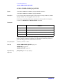
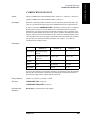
Manual Printing History
The manual’s printing date and part number indicate its current edition. The printing date
changes whenever a new edition is printed (minor corrections and updates incorporated at
reprint do not cause the date to change). The manual part number changes when extensive
technical changes are incorporated.
January 2000
Preliminary (Agilent P/N: 04287-90001)
February 2000
First Edition (Agilent P/N: 04287-90011)
March 2000
Second Edition (Agilent P/N: 04287-90021)
April 2000
Third Edition (Agilent P/N: 04287-90031)
August 2000
Fourth Edition(Agilent P/N: 04287-90041)
January 2001
Fifth Edition (Agilent P/N: 04287-90051)
November 2002
Sixth Edition (Agilent P/N: 04287-90061)
May 2003
Seventh Edition (Agilent P/N: 04287-90071)
2
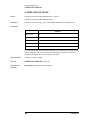
Typeface Conventions
Bold
Boldface type is used for terms that are defined.
For example: icons are symbols.
Italic
Italic type is used for emphasis and for titles of
manuals and other publications.
[Hardkey]
Indicates a hardkey labeled “Hardkey.”
Softkey
Indicates a softkey labeled “Softkey.”
[Hardkey] - Softkey1 - Softkey2
Indicates keystrokes [Hardkey] - Softkey1 Softkey2.
Sample Program Disk
A sample program disk (Agilent Part Number 04287-18030) is furnished with this manual.
The disk contains the sample programs used in this manual.
The customer shall have the personal, non-transferable rights to use, copy, or modify
SAMPLE PROGRAMS in this manual for the Customer’s internal operations. The
customer shall use the SAMPLE PROGRAMS solely and exclusively for their own
purposes and shall not license, lease, market, or distribute the SAMPLE PROGRAMS or
modification of any part thereof.
Agilent Technologies shall not be liable for the quality, performance, or behavior of the
SAMPLE PROGRAMS. Agilent Technologies especially disclaims any responsibility for
the operation of the SAMPLE PROGRAMS to be uninterrupted or error-free. The
SAMPLE PROGRAMS are provided AS IS.
AGILENT TECHNOLOGIES DISCLAIMS ANY IMPLIED WARRANTY OF
MERCHANTABILITY AND FITNESS FOR A PARTICULAR PURPOSE.
Agilent Technologies shall not be liable for any infringement of any patent, trademark,
copyright, or other proprietary right by the SAMPLE PROGRAMS or their use. Agilent
Technologies does not warrant that the SAMPLE PROGRAMS are free from
infringements of such rights of third parties. However, Agilent Technologies will not
knowingly infringe or deliver software that infringes the patent, trademark, copyright, or
other proprietary right of a third party.
3
4287A Documentation Map
The following manuals are available for the 4287A.
•
Operation Manual (Agilent P/N: 04287-900x4)
Basic information needed for using the 4287A is given in this manual. It includes
guidelines for installation, preparation, and measurement operations, including
calibration, performances (specifications), key definitions, and error messages. For
GPIB programming, see the Programming Manual.
•
Programming Manual (Agilent P/N: 04287-900x1)
The Programming Manual shows how to write and use BASIC programs to control the
4287A.
4
Contents
1. To Make Effective Use of This Manual
Contents of This Manual. . . . . . . . . . . . . . . . . . . . . . . . . . . . . . . . . . . . . . . . . . . . . . . . . . . . . . . . . . . . . . . . 14
How To Use This Manual . . . . . . . . . . . . . . . . . . . . . . . . . . . . . . . . . . . . . . . . . . . . . . . . . . . . . . . . . . . . . . . 17
Looking up GPIB commands . . . . . . . . . . . . . . . . . . . . . . . . . . . . . . . . . . . . . . . . . . . . . . . . . . . . . . . . . . 17
Using sample programs. . . . . . . . . . . . . . . . . . . . . . . . . . . . . . . . . . . . . . . . . . . . . . . . . . . . . . . . . . . . . . . 17
2. Overview of Remote Control
Setting Up a GPIB Remote Control System . . . . . . . . . . . . . . . . . . . . . . . . . . . . . . . . . . . . . . . . . . . . . . . . . 20
What is GPIB?. . . . . . . . . . . . . . . . . . . . . . . . . . . . . . . . . . . . . . . . . . . . . . . . . . . . . . . . . . . . . . . . . . . . . . 20
How to set up a GPIB remote control system . . . . . . . . . . . . . . . . . . . . . . . . . . . . . . . . . . . . . . . . . . . . . . 20
Device selector . . . . . . . . . . . . . . . . . . . . . . . . . . . . . . . . . . . . . . . . . . . . . . . . . . . . . . . . . . . . . . . . . . . . . 21
Sending GPIB Command Messages . . . . . . . . . . . . . . . . . . . . . . . . . . . . . . . . . . . . . . . . . . . . . . . . . . . . . . . 22
Types and structure of GPIB commands. . . . . . . . . . . . . . . . . . . . . . . . . . . . . . . . . . . . . . . . . . . . . . . . . . 22
Message syntax . . . . . . . . . . . . . . . . . . . . . . . . . . . . . . . . . . . . . . . . . . . . . . . . . . . . . . . . . . . . . . . . . . . . . 23
Remote mode. . . . . . . . . . . . . . . . . . . . . . . . . . . . . . . . . . . . . . . . . . . . . . . . . . . . . . . . . . . . . . . . . . . . . . . 24
3. Specifying Measurement Conditions
Setting Measurement Parameters . . . . . . . . . . . . . . . . . . . . . . . . . . . . . . . . . . . . . . . . . . . . . . . . . . . . . . . . . 26
Setting Measurement Point Setup Tables (Signal Source and Averaging Factor) . . . . . . . . . . . . . . . . . . . . 27
Choosing Whether to Measure the DUT at a Single Point or Multiple Points. . . . . . . . . . . . . . . . . . . . . . . 28
Configuring the Instrument for Rdc Measurement. . . . . . . . . . . . . . . . . . . . . . . . . . . . . . . . . . . . . . . . . . . . 28
Turning on/off the Rdc measurement function . . . . . . . . . . . . . . . . . . . . . . . . . . . . . . . . . . . . . . . . . . . . . 28
Turning on/off the offset cancel function . . . . . . . . . . . . . . . . . . . . . . . . . . . . . . . . . . . . . . . . . . . . . . . . . 28
Setting the limit range for Rdc measurement . . . . . . . . . . . . . . . . . . . . . . . . . . . . . . . . . . . . . . . . . . . . . . 28
Setting How the Instrument Displays Measurement Results (Enabling/Disabling Deviation Measurement
Mode) . . . . . . . . . . . . . . . . . . . . . . . . . . . . . . . . . . . . . . . . . . . . . . . . . . . . . . . . . . . . . . . . . . . . . . . . . . . . . . 29
Configuring Screen Display . . . . . . . . . . . . . . . . . . . . . . . . . . . . . . . . . . . . . . . . . . . . . . . . . . . . . . . . . . . . . 30
Configuring the display of measurement results. . . . . . . . . . . . . . . . . . . . . . . . . . . . . . . . . . . . . . . . . . . . 30
Setting the display items on the list measurement screen . . . . . . . . . . . . . . . . . . . . . . . . . . . . . . . . . . . . . 31
Turning on/off the display . . . . . . . . . . . . . . . . . . . . . . . . . . . . . . . . . . . . . . . . . . . . . . . . . . . . . . . . . . . . . 31
Turning on/off the update of the display . . . . . . . . . . . . . . . . . . . . . . . . . . . . . . . . . . . . . . . . . . . . . . . . . . 31
Turning on/off the backlight of the LCD screen . . . . . . . . . . . . . . . . . . . . . . . . . . . . . . . . . . . . . . . . . . . . 31
Showing or hiding the title . . . . . . . . . . . . . . . . . . . . . . . . . . . . . . . . . . . . . . . . . . . . . . . . . . . . . . . . . . . . 31
Turning on/off the date display . . . . . . . . . . . . . . . . . . . . . . . . . . . . . . . . . . . . . . . . . . . . . . . . . . . . . . . . . 31
Sample Program . . . . . . . . . . . . . . . . . . . . . . . . . . . . . . . . . . . . . . . . . . . . . . . . . . . . . . . . . . . . . . . . . . . . . . 32
4. Preparing for Accurate Measurement
Performing Calibration . . . . . . . . . . . . . . . . . . . . . . . . . . . . . . . . . . . . . . . . . . . . . . . . . . . . . . . . . . . . . . . . . 38
Setting calibration kit values . . . . . . . . . . . . . . . . . . . . . . . . . . . . . . . . . . . . . . . . . . . . . . . . . . . . . . . . . . . 38
Measuring data for calculating calibration coefficients and turning on calibration function . . . . . . . . . . 38
Preventing operational errors when measuring data for calculating calibration coefficients . . . . . . . . . . 40
Saving or recalling calibrated state (retrieving or writing calibration coefficients) . . . . . . . . . . . . . . . . . 41
Sample program . . . . . . . . . . . . . . . . . . . . . . . . . . . . . . . . . . . . . . . . . . . . . . . . . . . . . . . . . . . . . . . . . . . . 42
Selecting a Test Fixture (Port Extension Compensation) . . . . . . . . . . . . . . . . . . . . . . . . . . . . . . . . . . . . . . . 51
Using port extension compensation function . . . . . . . . . . . . . . . . . . . . . . . . . . . . . . . . . . . . . . . . . . . . . . 51
Configuring the instrument to use your custom test fixture . . . . . . . . . . . . . . . . . . . . . . . . . . . . . . . . . . . 51
Running the Compensation Process . . . . . . . . . . . . . . . . . . . . . . . . . . . . . . . . . . . . . . . . . . . . . . . . . . . . . . . 52
Setting compensation kit values . . . . . . . . . . . . . . . . . . . . . . . . . . . . . . . . . . . . . . . . . . . . . . . . . . . . . . . . 52
5
Contents
Measuring data for calculating compensation coefficients. . . . . . . . . . . . . . . . . . . . . . . . . . . . . . . . . . . .
Calculating compensation coefficients and turning on/off compensation function . . . . . . . . . . . . . . . . .
Preventing operational errors when measuring data for calculating compensation coefficients . . . . . . .
Saving or recalling compensated state (retrieving or writing compensation coefficients). . . . . . . . . . . .
Sample program . . . . . . . . . . . . . . . . . . . . . . . . . . . . . . . . . . . . . . . . . . . . . . . . . . . . . . . . . . . . . . . . . . . .
52
54
54
55
56
5. Starting Measurement Cycle (Triggering) and Detecting End of Measurement
Starting a New Measurement Cycle (Triggering) . . . . . . . . . . . . . . . . . . . . . . . . . . . . . . . . . . . . . . . . . . . .
Trigger system. . . . . . . . . . . . . . . . . . . . . . . . . . . . . . . . . . . . . . . . . . . . . . . . . . . . . . . . . . . . . . . . . . . . . .
Starting a measurement cycle (Triggering the instrument). . . . . . . . . . . . . . . . . . . . . . . . . . . . . . . . . . . .
Waiting for (Detecting) End of Measurement . . . . . . . . . . . . . . . . . . . . . . . . . . . . . . . . . . . . . . . . . . . . . . .
Sample program . . . . . . . . . . . . . . . . . . . . . . . . . . . . . . . . . . . . . . . . . . . . . . . . . . . . . . . . . . . . . . . . . . . .
66
66
69
70
71
6. Retrieving Measurement Results
Data Transfer Format . . . . . . . . . . . . . . . . . . . . . . . . . . . . . . . . . . . . . . . . . . . . . . . . . . . . . . . . . . . . . . . . . . 74
ASCII format . . . . . . . . . . . . . . . . . . . . . . . . . . . . . . . . . . . . . . . . . . . . . . . . . . . . . . . . . . . . . . . . . . . . . . 75
Binary format . . . . . . . . . . . . . . . . . . . . . . . . . . . . . . . . . . . . . . . . . . . . . . . . . . . . . . . . . . . . . . . . . . . . . . 76
Internal Data Processing. . . . . . . . . . . . . . . . . . . . . . . . . . . . . . . . . . . . . . . . . . . . . . . . . . . . . . . . . . . . . . . . 77
Data flow. . . . . . . . . . . . . . . . . . . . . . . . . . . . . . . . . . . . . . . . . . . . . . . . . . . . . . . . . . . . . . . . . . . . . . . . . . 77
Internal data arrays . . . . . . . . . . . . . . . . . . . . . . . . . . . . . . . . . . . . . . . . . . . . . . . . . . . . . . . . . . . . . . . . . . 78
Retrieving the Measurement Results for Measurement Parameters 1 through 4 . . . . . . . . . . . . . . . . . . . . . 85
Using the *TRG command to retrieve measurement results . . . . . . . . . . . . . . . . . . . . . . . . . . . . . . . . . . 86
Using the :FETC? or :DATA:FDAT{1-4}? command to retrieve measurement results . . . . . . . . . . . . . 90
Using the :READ? command to retrieve measurement results . . . . . . . . . . . . . . . . . . . . . . . . . . . . . . . . 96
Retrieving the Monitored Values of Test Signal Levels. . . . . . . . . . . . . . . . . . . . . . . . . . . . . . . . . . . . . . . . 99
Retrieving the Results of Rdc Measurement . . . . . . . . . . . . . . . . . . . . . . . . . . . . . . . . . . . . . . . . . . . . . . . 101
Retrieving measurement results . . . . . . . . . . . . . . . . . . . . . . . . . . . . . . . . . . . . . . . . . . . . . . . . . . . . . . . 101
Retrieving limit test results . . . . . . . . . . . . . . . . . . . . . . . . . . . . . . . . . . . . . . . . . . . . . . . . . . . . . . . . . . . 101
Sample program . . . . . . . . . . . . . . . . . . . . . . . . . . . . . . . . . . . . . . . . . . . . . . . . . . . . . . . . . . . . . . . . . . . 102
7. Sorting DUTs Based on Measurement Results
Setting Up the Bin Sorting Function . . . . . . . . . . . . . . . . . . . . . . . . . . . . . . . . . . . . . . . . . . . . . . . . . . . . .
Turning on/off the bin sorting function (comparator). . . . . . . . . . . . . . . . . . . . . . . . . . . . . . . . . . . . . . .
Setting the beep condition. . . . . . . . . . . . . . . . . . . . . . . . . . . . . . . . . . . . . . . . . . . . . . . . . . . . . . . . . . . .
Setting the sorting conditions for each bin . . . . . . . . . . . . . . . . . . . . . . . . . . . . . . . . . . . . . . . . . . . . . . .
Retrieving the Results of Bin Sorting. . . . . . . . . . . . . . . . . . . . . . . . . . . . . . . . . . . . . . . . . . . . . . . . . . . . .
Retrieving the Number of the DUTs Sorted into Each Bin (Using the Bin Count Function) . . . . . . . . . .
Sample Program . . . . . . . . . . . . . . . . . . . . . . . . . . . . . . . . . . . . . . . . . . . . . . . . . . . . . . . . . . . . . . . . . . . . .
106
106
106
106
110
111
112
8. Statistical Analysis of Measurement Results
Capturing the Measurement Data for Statistical Analysis . . . . . . . . . . . . . . . . . . . . . . . . . . . . . . . . . . . . .
Setting the number of data segments to capture . . . . . . . . . . . . . . . . . . . . . . . . . . . . . . . . . . . . . . . . . . .
Starting data capture . . . . . . . . . . . . . . . . . . . . . . . . . . . . . . . . . . . . . . . . . . . . . . . . . . . . . . . . . . . . . . . .
Completion of data capture. . . . . . . . . . . . . . . . . . . . . . . . . . . . . . . . . . . . . . . . . . . . . . . . . . . . . . . . . . .
Saving the captured data . . . . . . . . . . . . . . . . . . . . . . . . . . . . . . . . . . . . . . . . . . . . . . . . . . . . . . . . . . . . .
Performing Statistical Analysis . . . . . . . . . . . . . . . . . . . . . . . . . . . . . . . . . . . . . . . . . . . . . . . . . . . . . . . . .
Sample Program . . . . . . . . . . . . . . . . . . . . . . . . . . . . . . . . . . . . . . . . . . . . . . . . . . . . . . . . . . . . . . . . . . . . .
118
118
118
118
118
119
120
6
Contents
9. Saving and Recalling Files
Saving and Recalling Files . . . . . . . . . . . . . . . . . . . . . . . . . . . . . . . . . . . . . . . . . . . . . . . . . . . . . . . . . . . . . 126
Specifying the file . . . . . . . . . . . . . . . . . . . . . . . . . . . . . . . . . . . . . . . . . . . . . . . . . . . . . . . . . . . . . . . . . . 126
Saving data to a file. . . . . . . . . . . . . . . . . . . . . . . . . . . . . . . . . . . . . . . . . . . . . . . . . . . . . . . . . . . . . . . . . 126
Recalling a file . . . . . . . . . . . . . . . . . . . . . . . . . . . . . . . . . . . . . . . . . . . . . . . . . . . . . . . . . . . . . . . . . . . . 127
Automatically recalling a file . . . . . . . . . . . . . . . . . . . . . . . . . . . . . . . . . . . . . . . . . . . . . . . . . . . . . . . . . 127
Managing a file . . . . . . . . . . . . . . . . . . . . . . . . . . . . . . . . . . . . . . . . . . . . . . . . . . . . . . . . . . . . . . . . . . . . 127
Sample Program . . . . . . . . . . . . . . . . . . . . . . . . . . . . . . . . . . . . . . . . . . . . . . . . . . . . . . . . . . . . . . . . . . . . . 128
10. Error Handling
Using the Error Queue . . . . . . . . . . . . . . . . . . . . . . . . . . . . . . . . . . . . . . . . . . . . . . . . . . . . . . . . . . . . . . . . 134
Using the Status Reporting System. . . . . . . . . . . . . . . . . . . . . . . . . . . . . . . . . . . . . . . . . . . . . . . . . . . . . . . 135
Sample Program . . . . . . . . . . . . . . . . . . . . . . . . . . . . . . . . . . . . . . . . . . . . . . . . . . . . . . . . . . . . . . . . . . . . . 136
11. Shutting Down the Instrument
Shutdown Procedure . . . . . . . . . . . . . . . . . . . . . . . . . . . . . . . . . . . . . . . . . . . . . . . . . . . . . . . . . . . . . . . . . . 140
12. Connecting the Instrument to a Handler with the Handler Interface
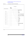
Input/Output Signal Pin Layout . . . . . . . . . . . . . . . . . . . . . . . . . . . . . . . . . . . . . . . . . . . . . . . . . . . . . . . . . 142
Outputting Bin Sort Results . . . . . . . . . . . . . . . . . . . . . . . . . . . . . . . . . . . . . . . . . . . . . . . . . . . . . . . . . . . . 144
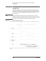
Timing Chart. . . . . . . . . . . . . . . . . . . . . . . . . . . . . . . . . . . . . . . . . . . . . . . . . . . . . . . . . . . . . . . . . . . . . . . . 146
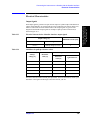
Electrical Characteristics . . . . . . . . . . . . . . . . . . . . . . . . . . . . . . . . . . . . . . . . . . . . . . . . . . . . . . . . . . . . . . 147
Output signals . . . . . . . . . . . . . . . . . . . . . . . . . . . . . . . . . . . . . . . . . . . . . . . . . . . . . . . . . . . . . . . . . . . . . 147
Input signals . . . . . . . . . . . . . . . . . . . . . . . . . . . . . . . . . . . . . . . . . . . . . . . . . . . . . . . . . . . . . . . . . . . . . . 149
Output signal pull-up/input signal drive voltage. . . . . . . . . . . . . . . . . . . . . . . . . . . . . . . . . . . . . . . . . . . 150
Modification of the Handler Interface . . . . . . . . . . . . . . . . . . . . . . . . . . . . . . . . . . . . . . . . . . . . . . . . . . . . 151
Setting the drive/pull-up power supply . . . . . . . . . . . . . . . . . . . . . . . . . . . . . . . . . . . . . . . . . . . . . . . . . . 151
Setting the pull-up resistors. . . . . . . . . . . . . . . . . . . . . . . . . . . . . . . . . . . . . . . . . . . . . . . . . . . . . . . . . . . 152
Procedure for removing the handler interface board . . . . . . . . . . . . . . . . . . . . . . . . . . . . . . . . . . . . . . . 154
13. Using LAN
Advantages of LAN Connections . . . . . . . . . . . . . . . . . . . . . . . . . . . . . . . . . . . . . . . . . . . . . . . . . . . . . . . . 158
Preparing to Use a LAN . . . . . . . . . . . . . . . . . . . . . . . . . . . . . . . . . . . . . . . . . . . . . . . . . . . . . . . . . . . . . . . 159
Setting up LAN connections . . . . . . . . . . . . . . . . . . . . . . . . . . . . . . . . . . . . . . . . . . . . . . . . . . . . . . . . . . 159
Connecting to a LAN . . . . . . . . . . . . . . . . . . . . . . . . . . . . . . . . . . . . . . . . . . . . . . . . . . . . . . . . . . . . . . . 160
Transferring Files . . . . . . . . . . . . . . . . . . . . . . . . . . . . . . . . . . . . . . . . . . . . . . . . . . . . . . . . . . . . . . . . . . . . 161
File transfer procedure using ftp . . . . . . . . . . . . . . . . . . . . . . . . . . . . . . . . . . . . . . . . . . . . . . . . . . . . . . . 161
File transfer procedure using a file transfer application . . . . . . . . . . . . . . . . . . . . . . . . . . . . . . . . . . . . . 162
Interactive Control by Telnet . . . . . . . . . . . . . . . . . . . . . . . . . . . . . . . . . . . . . . . . . . . . . . . . . . . . . . . . . . . 164
14. Using Printer
Preparation for Printing . . . . . . . . . . . . . . . . . . . . . . . . . . . . . . . . . . . . . . . . . . . . . . . . . . . . . . . . . . . . . . . 168
Checking supported printers . . . . . . . . . . . . . . . . . . . . . . . . . . . . . . . . . . . . . . . . . . . . . . . . . . . . . . . . . . 168
Selecting a printer . . . . . . . . . . . . . . . . . . . . . . . . . . . . . . . . . . . . . . . . . . . . . . . . . . . . . . . . . . . . . . . . . . 168
Outputting the Data to the Printer. . . . . . . . . . . . . . . . . . . . . . . . . . . . . . . . . . . . . . . . . . . . . . . . . . . . . . . . 169
Selecting what to output . . . . . . . . . . . . . . . . . . . . . . . . . . . . . . . . . . . . . . . . . . . . . . . . . . . . . . . . . . . . . 169
Selecting the color scheme . . . . . . . . . . . . . . . . . . . . . . . . . . . . . . . . . . . . . . . . . . . . . . . . . . . . . . . . . . . 169
Starting a print operation. . . . . . . . . . . . . . . . . . . . . . . . . . . . . . . . . . . . . . . . . . . . . . . . . . . . . . . . . . . . . 169
7
Contents
Canceling the print operating . . . . . . . . . . . . . . . . . . . . . . . . . . . . . . . . . . . . . . . . . . . . . . . . . . . . . . . . . 169
Sample Program . . . . . . . . . . . . . . . . . . . . . . . . . . . . . . . . . . . . . . . . . . . . . . . . . . . . . . . . . . . . . . . . . . . . . 170
15. Sample Application Programs
Measuring the DUT with a Test Fixture. . . . . . . . . . . . . . . . . . . . . . . . . . . . . . . . . . . . . . . . . . . . . . . . . . .
Using an Auto-sorting System . . . . . . . . . . . . . . . . . . . . . . . . . . . . . . . . . . . . . . . . . . . . . . . . . . . . . . . . . .
Measuring Array (Multi-Element) Components . . . . . . . . . . . . . . . . . . . . . . . . . . . . . . . . . . . . . . . . . . . .
Sample Program . . . . . . . . . . . . . . . . . . . . . . . . . . . . . . . . . . . . . . . . . . . . . . . . . . . . . . . . . . . . . . . . . . .
174
182
192
193
16. Command Reference
Notational Conventions in this Command Reference . . . . . . . . . . . . . . . . . . . . . . . . . . . . . . . . . . . . . . . .
Syntax . . . . . . . . . . . . . . . . . . . . . . . . . . . . . . . . . . . . . . . . . . . . . . . . . . . . . . . . . . . . . . . . . . . . . . . . . . .
Description . . . . . . . . . . . . . . . . . . . . . . . . . . . . . . . . . . . . . . . . . . . . . . . . . . . . . . . . . . . . . . . . . . . . . . .
Parameters. . . . . . . . . . . . . . . . . . . . . . . . . . . . . . . . . . . . . . . . . . . . . . . . . . . . . . . . . . . . . . . . . . . . . . . .
Query response . . . . . . . . . . . . . . . . . . . . . . . . . . . . . . . . . . . . . . . . . . . . . . . . . . . . . . . . . . . . . . . . . . . .
See also . . . . . . . . . . . . . . . . . . . . . . . . . . . . . . . . . . . . . . . . . . . . . . . . . . . . . . . . . . . . . . . . . . . . . . . . . .
Equivalent key sequence. . . . . . . . . . . . . . . . . . . . . . . . . . . . . . . . . . . . . . . . . . . . . . . . . . . . . . . . . . . . .
IEEE Common Commands . . . . . . . . . . . . . . . . . . . . . . . . . . . . . . . . . . . . . . . . . . . . . . . . . . . . . . . . . . . .
*CLS . . . . . . . . . . . . . . . . . . . . . . . . . . . . . . . . . . . . . . . . . . . . . . . . . . . . . . . . . . . . . . . . . . . . . . . . . . . .
*ESE . . . . . . . . . . . . . . . . . . . . . . . . . . . . . . . . . . . . . . . . . . . . . . . . . . . . . . . . . . . . . . . . . . . . . . . . . . . .
*ESR? . . . . . . . . . . . . . . . . . . . . . . . . . . . . . . . . . . . . . . . . . . . . . . . . . . . . . . . . . . . . . . . . . . . . . . . . . . .
*IDN? . . . . . . . . . . . . . . . . . . . . . . . . . . . . . . . . . . . . . . . . . . . . . . . . . . . . . . . . . . . . . . . . . . . . . . . . . . .
*OPC. . . . . . . . . . . . . . . . . . . . . . . . . . . . . . . . . . . . . . . . . . . . . . . . . . . . . . . . . . . . . . . . . . . . . . . . . . . .
*OPC?. . . . . . . . . . . . . . . . . . . . . . . . . . . . . . . . . . . . . . . . . . . . . . . . . . . . . . . . . . . . . . . . . . . . . . . . . . .
*RST . . . . . . . . . . . . . . . . . . . . . . . . . . . . . . . . . . . . . . . . . . . . . . . . . . . . . . . . . . . . . . . . . . . . . . . . . . . .
*SRE . . . . . . . . . . . . . . . . . . . . . . . . . . . . . . . . . . . . . . . . . . . . . . . . . . . . . . . . . . . . . . . . . . . . . . . . . . . .
*STB? . . . . . . . . . . . . . . . . . . . . . . . . . . . . . . . . . . . . . . . . . . . . . . . . . . . . . . . . . . . . . . . . . . . . . . . . . . .
*TRG . . . . . . . . . . . . . . . . . . . . . . . . . . . . . . . . . . . . . . . . . . . . . . . . . . . . . . . . . . . . . . . . . . . . . . . . . . .
*TST? . . . . . . . . . . . . . . . . . . . . . . . . . . . . . . . . . . . . . . . . . . . . . . . . . . . . . . . . . . . . . . . . . . . . . . . . . . .
*WAI. . . . . . . . . . . . . . . . . . . . . . . . . . . . . . . . . . . . . . . . . . . . . . . . . . . . . . . . . . . . . . . . . . . . . . . . . . . .
4287A GPIB Commands . . . . . . . . . . . . . . . . . . . . . . . . . . . . . . . . . . . . . . . . . . . . . . . . . . . . . . . . . . . . . .
:ABOR . . . . . . . . . . . . . . . . . . . . . . . . . . . . . . . . . . . . . . . . . . . . . . . . . . . . . . . . . . . . . . . . . . . . . . . . . .
:AVER:COUN. . . . . . . . . . . . . . . . . . . . . . . . . . . . . . . . . . . . . . . . . . . . . . . . . . . . . . . . . . . . . . . . . . . . .
:CALC:COMP . . . . . . . . . . . . . . . . . . . . . . . . . . . . . . . . . . . . . . . . . . . . . . . . . . . . . . . . . . . . . . . . . . . .
:CALC:COMP:BEEP:COND. . . . . . . . . . . . . . . . . . . . . . . . . . . . . . . . . . . . . . . . . . . . . . . . . . . . . . . . .
:CALC:COMP:BIN{1-13} . . . . . . . . . . . . . . . . . . . . . . . . . . . . . . . . . . . . . . . . . . . . . . . . . . . . . . . . . . .
:CALC:COMP:BIN{1-13}:COND{1-4}:LIM . . . . . . . . . . . . . . . . . . . . . . . . . . . . . . . . . . . . . . . . . . . .
:CALC:COMP:BIN{1-13}:COND{1-4}:LTYP. . . . . . . . . . . . . . . . . . . . . . . . . . . . . . . . . . . . . . . . . . .
:CALC:COMP:CLE . . . . . . . . . . . . . . . . . . . . . . . . . . . . . . . . . . . . . . . . . . . . . . . . . . . . . . . . . . . . . . . .
:CALC:COMP:COND{1-4}:MODE . . . . . . . . . . . . . . . . . . . . . . . . . . . . . . . . . . . . . . . . . . . . . . . . . . .
:CALC:COMP:COND{1-4}:NOM . . . . . . . . . . . . . . . . . . . . . . . . . . . . . . . . . . . . . . . . . . . . . . . . . . . .
:CALC:COMP:COND{1-4}:PAR . . . . . . . . . . . . . . . . . . . . . . . . . . . . . . . . . . . . . . . . . . . . . . . . . . . . .
:CALC:COMP:COND{1-4}:SNUM . . . . . . . . . . . . . . . . . . . . . . . . . . . . . . . . . . . . . . . . . . . . . . . . . . .
:CALC:COMP:COUN . . . . . . . . . . . . . . . . . . . . . . . . . . . . . . . . . . . . . . . . . . . . . . . . . . . . . . . . . . . . . .
:CALC:COMP:COUN:CLE . . . . . . . . . . . . . . . . . . . . . . . . . . . . . . . . . . . . . . . . . . . . . . . . . . . . . . . . . .
:CALC:COMP:DATA:BCOU?. . . . . . . . . . . . . . . . . . . . . . . . . . . . . . . . . . . . . . . . . . . . . . . . . . . . . . . .
:CALC:COMP:DATA:BIN? . . . . . . . . . . . . . . . . . . . . . . . . . . . . . . . . . . . . . . . . . . . . . . . . . . . . . . . . . .
:CALC:COMP:DATA:RDC? . . . . . . . . . . . . . . . . . . . . . . . . . . . . . . . . . . . . . . . . . . . . . . . . . . . . . . . . .
202
202
202
202
203
203
203
204
204
204
205
205
205
205
206
207
207
208
208
208
209
209
210
211
211
212
213
214
214
215
216
217
218
219
219
220
221
222
8
Contents
:CALC:COMP:OGB . . . . . . . . . . . . . . . . . . . . . . . . . . . . . . . . . . . . . . . . . . . . . . . . . . . . . . . . . . . . . . . . 223
:CALC:COMP:RDC:LIM. . . . . . . . . . . . . . . . . . . . . . . . . . . . . . . . . . . . . . . . . . . . . . . . . . . . . . . . . . . . 224
:CALC:EXAM:GET? . . . . . . . . . . . . . . . . . . . . . . . . . . . . . . . . . . . . . . . . . . . . . . . . . . . . . . . . . . . . . . . 225
:CALC:EXAM:POIN? . . . . . . . . . . . . . . . . . . . . . . . . . . . . . . . . . . . . . . . . . . . . . . . . . . . . . . . . . . . . . . 226
:CALC:EXAM:SIZE. . . . . . . . . . . . . . . . . . . . . . . . . . . . . . . . . . . . . . . . . . . . . . . . . . . . . . . . . . . . . . . . 227
:CALC:EXAM:STAR . . . . . . . . . . . . . . . . . . . . . . . . . . . . . . . . . . . . . . . . . . . . . . . . . . . . . . . . . . . . . . . 228
:CALC:PAR{1-4}:EXPR:CENT. . . . . . . . . . . . . . . . . . . . . . . . . . . . . . . . . . . . . . . . . . . . . . . . . . . . . . . 228
:CALC:PAR{1-4}:EXPR:NAME . . . . . . . . . . . . . . . . . . . . . . . . . . . . . . . . . . . . . . . . . . . . . . . . . . . . . . 229
:CALC:PAR{1-4}:EXPR:STAT . . . . . . . . . . . . . . . . . . . . . . . . . . . . . . . . . . . . . . . . . . . . . . . . . . . . . . . 229
:CALC:PAR{1-4}:FORM . . . . . . . . . . . . . . . . . . . . . . . . . . . . . . . . . . . . . . . . . . . . . . . . . . . . . . . . . . . . 230
:CORR1? . . . . . . . . . . . . . . . . . . . . . . . . . . . . . . . . . . . . . . . . . . . . . . . . . . . . . . . . . . . . . . . . . . . . . . . . . 231
:CORR1:CKIT . . . . . . . . . . . . . . . . . . . . . . . . . . . . . . . . . . . . . . . . . . . . . . . . . . . . . . . . . . . . . . . . . . . . 231
:CORR1:CKIT:LIST . . . . . . . . . . . . . . . . . . . . . . . . . . . . . . . . . . . . . . . . . . . . . . . . . . . . . . . . . . . . . . . . 232
:CORR1:CKIT:STAN1:DC. . . . . . . . . . . . . . . . . . . . . . . . . . . . . . . . . . . . . . . . . . . . . . . . . . . . . . . . . . . 233
:CORR1:CKIT:STAN1:EDEL . . . . . . . . . . . . . . . . . . . . . . . . . . . . . . . . . . . . . . . . . . . . . . . . . . . . . . . . 234
:CORR1:CKIT:STAN1:LIST . . . . . . . . . . . . . . . . . . . . . . . . . . . . . . . . . . . . . . . . . . . . . . . . . . . . . . . . . 235
:CORR1:CKIT:STAN2:DC. . . . . . . . . . . . . . . . . . . . . . . . . . . . . . . . . . . . . . . . . . . . . . . . . . . . . . . . . . . 236
:CORR1:CKIT:STAN2:EDEL . . . . . . . . . . . . . . . . . . . . . . . . . . . . . . . . . . . . . . . . . . . . . . . . . . . . . . . . 237
:CORR1:CKIT:STAN2:LIST . . . . . . . . . . . . . . . . . . . . . . . . . . . . . . . . . . . . . . . . . . . . . . . . . . . . . . . . . 238
:CORR1:CKIT:STAN3:DC. . . . . . . . . . . . . . . . . . . . . . . . . . . . . . . . . . . . . . . . . . . . . . . . . . . . . . . . . . . 239
:CORR1:CKIT:STAN3:EDEL . . . . . . . . . . . . . . . . . . . . . . . . . . . . . . . . . . . . . . . . . . . . . . . . . . . . . . . . 240
:CORR1:CKIT:STAN3:FORM . . . . . . . . . . . . . . . . . . . . . . . . . . . . . . . . . . . . . . . . . . . . . . . . . . . . . . . . 241
:CORR1:CKIT:STAN3:LIST . . . . . . . . . . . . . . . . . . . . . . . . . . . . . . . . . . . . . . . . . . . . . . . . . . . . . . . . . 242
:CORR1:COLL . . . . . . . . . . . . . . . . . . . . . . . . . . . . . . . . . . . . . . . . . . . . . . . . . . . . . . . . . . . . . . . . . . . . 244
:CORR1:COLL:DC. . . . . . . . . . . . . . . . . . . . . . . . . . . . . . . . . . . . . . . . . . . . . . . . . . . . . . . . . . . . . . . . . 245
:CORR1:COLL:RF . . . . . . . . . . . . . . . . . . . . . . . . . . . . . . . . . . . . . . . . . . . . . . . . . . . . . . . . . . . . . . . . . 246
:CORR1:COLL:SAVE . . . . . . . . . . . . . . . . . . . . . . . . . . . . . . . . . . . . . . . . . . . . . . . . . . . . . . . . . . . . . . 246
:CORR2:CKIT . . . . . . . . . . . . . . . . . . . . . . . . . . . . . . . . . . . . . . . . . . . . . . . . . . . . . . . . . . . . . . . . . . . . 247
:CORR2:CKIT:LIST . . . . . . . . . . . . . . . . . . . . . . . . . . . . . . . . . . . . . . . . . . . . . . . . . . . . . . . . . . . . . . . . 247
:CORR2:CKIT:STAN1:DC. . . . . . . . . . . . . . . . . . . . . . . . . . . . . . . . . . . . . . . . . . . . . . . . . . . . . . . . . . . 248
:CORR2:CKIT:STAN1:LIST . . . . . . . . . . . . . . . . . . . . . . . . . . . . . . . . . . . . . . . . . . . . . . . . . . . . . . . . . 249
:CORR2:CKIT:STAN2:DC. . . . . . . . . . . . . . . . . . . . . . . . . . . . . . . . . . . . . . . . . . . . . . . . . . . . . . . . . . . 250
:CORR2:CKIT:STAN2:LIST . . . . . . . . . . . . . . . . . . . . . . . . . . . . . . . . . . . . . . . . . . . . . . . . . . . . . . . . . 251
:CORR2:COLL . . . . . . . . . . . . . . . . . . . . . . . . . . . . . . . . . . . . . . . . . . . . . . . . . . . . . . . . . . . . . . . . . . . . 252
:CORR2:COLL:DC. . . . . . . . . . . . . . . . . . . . . . . . . . . . . . . . . . . . . . . . . . . . . . . . . . . . . . . . . . . . . . . . . 253
:CORR2:COLL:OPEN . . . . . . . . . . . . . . . . . . . . . . . . . . . . . . . . . . . . . . . . . . . . . . . . . . . . . . . . . . . . . . 254
:CORR2:COLL:RF . . . . . . . . . . . . . . . . . . . . . . . . . . . . . . . . . . . . . . . . . . . . . . . . . . . . . . . . . . . . . . . . . 254
:CORR2:COLL:SAVE . . . . . . . . . . . . . . . . . . . . . . . . . . . . . . . . . . . . . . . . . . . . . . . . . . . . . . . . . . . . . . 255
:CORR2:COLL:SHOR . . . . . . . . . . . . . . . . . . . . . . . . . . . . . . . . . . . . . . . . . . . . . . . . . . . . . . . . . . . . . . 255
:CORR2:FIXT. . . . . . . . . . . . . . . . . . . . . . . . . . . . . . . . . . . . . . . . . . . . . . . . . . . . . . . . . . . . . . . . . . . . . 256
:CORR2:FIXT:EDEL:DIST . . . . . . . . . . . . . . . . . . . . . . . . . . . . . . . . . . . . . . . . . . . . . . . . . . . . . . . . . . 257
:CORR2:FIXT:LAB . . . . . . . . . . . . . . . . . . . . . . . . . . . . . . . . . . . . . . . . . . . . . . . . . . . . . . . . . . . . . . . . 258
:DATA:CAD{1-8}?. . . . . . . . . . . . . . . . . . . . . . . . . . . . . . . . . . . . . . . . . . . . . . . . . . . . . . . . . . . . . . . . . 259
:DATA:CCO{1-6}. . . . . . . . . . . . . . . . . . . . . . . . . . . . . . . . . . . . . . . . . . . . . . . . . . . . . . . . . . . . . . . . . . 260
:DATA:CMD{1-2}? . . . . . . . . . . . . . . . . . . . . . . . . . . . . . . . . . . . . . . . . . . . . . . . . . . . . . . . . . . . . . . . . 261
:DATA:CMP{1-3}. . . . . . . . . . . . . . . . . . . . . . . . . . . . . . . . . . . . . . . . . . . . . . . . . . . . . . . . . . . . . . . . . . 262
:DATA:FDAT{1-4}? . . . . . . . . . . . . . . . . . . . . . . . . . . . . . . . . . . . . . . . . . . . . . . . . . . . . . . . . . . . . . . . . 263
:DATA:IMON? . . . . . . . . . . . . . . . . . . . . . . . . . . . . . . . . . . . . . . . . . . . . . . . . . . . . . . . . . . . . . . . . . . . . 263
:DATA:RAW? . . . . . . . . . . . . . . . . . . . . . . . . . . . . . . . . . . . . . . . . . . . . . . . . . . . . . . . . . . . . . . . . . . . . . 264
9
Contents
:DATA:RCAD{1-3}? . . . . . . . . . . . . . . . . . . . . . . . . . . . . . . . . . . . . . . . . . . . . . . . . . . . . . . . . . . . . . . .
:DATA:RCCO{1-3} . . . . . . . . . . . . . . . . . . . . . . . . . . . . . . . . . . . . . . . . . . . . . . . . . . . . . . . . . . . . . . . .
:DATA:RCMD{1-2}? . . . . . . . . . . . . . . . . . . . . . . . . . . . . . . . . . . . . . . . . . . . . . . . . . . . . . . . . . . . . . . .
:DATA:RCMP{1-3} . . . . . . . . . . . . . . . . . . . . . . . . . . . . . . . . . . . . . . . . . . . . . . . . . . . . . . . . . . . . . . . .
:DATA:RDC? . . . . . . . . . . . . . . . . . . . . . . . . . . . . . . . . . . . . . . . . . . . . . . . . . . . . . . . . . . . . . . . . . . . . .
:DATA:VMON? . . . . . . . . . . . . . . . . . . . . . . . . . . . . . . . . . . . . . . . . . . . . . . . . . . . . . . . . . . . . . . . . . . .
:DISP. . . . . . . . . . . . . . . . . . . . . . . . . . . . . . . . . . . . . . . . . . . . . . . . . . . . . . . . . . . . . . . . . . . . . . . . . . . .
:DISP:BACK . . . . . . . . . . . . . . . . . . . . . . . . . . . . . . . . . . . . . . . . . . . . . . . . . . . . . . . . . . . . . . . . . . . . .
:DISP:CCL . . . . . . . . . . . . . . . . . . . . . . . . . . . . . . . . . . . . . . . . . . . . . . . . . . . . . . . . . . . . . . . . . . . . . . .
:DISP:TEXT1 . . . . . . . . . . . . . . . . . . . . . . . . . . . . . . . . . . . . . . . . . . . . . . . . . . . . . . . . . . . . . . . . . . . . .
:DISP:TEXT1:CALC{1-4} . . . . . . . . . . . . . . . . . . . . . . . . . . . . . . . . . . . . . . . . . . . . . . . . . . . . . . . . . .
:DISP:TEXT1:CALC{1-4}:DIG . . . . . . . . . . . . . . . . . . . . . . . . . . . . . . . . . . . . . . . . . . . . . . . . . . . . . .
:DISP:TEXT1:CALC{1-4}:FIX. . . . . . . . . . . . . . . . . . . . . . . . . . . . . . . . . . . . . . . . . . . . . . . . . . . . . . .
:DISP:TEXT1:CALC{1-4}:MSD. . . . . . . . . . . . . . . . . . . . . . . . . . . . . . . . . . . . . . . . . . . . . . . . . . . . . .
:DISP:TEXT1:CALC{11-12}. . . . . . . . . . . . . . . . . . . . . . . . . . . . . . . . . . . . . . . . . . . . . . . . . . . . . . . . .
:DISP:TEXT1:CALC{11-12}:DIG . . . . . . . . . . . . . . . . . . . . . . . . . . . . . . . . . . . . . . . . . . . . . . . . . . . .
:DISP:TEXT1:CALC{11-12}:FIX . . . . . . . . . . . . . . . . . . . . . . . . . . . . . . . . . . . . . . . . . . . . . . . . . . . . .
:DISP:TEXT1:CALC{11-12}:MSD. . . . . . . . . . . . . . . . . . . . . . . . . . . . . . . . . . . . . . . . . . . . . . . . . . . .
:DISP:TEXT1:CALC13:DIG . . . . . . . . . . . . . . . . . . . . . . . . . . . . . . . . . . . . . . . . . . . . . . . . . . . . . . . . .
:DISP:TEXT1:CALC13:FIX . . . . . . . . . . . . . . . . . . . . . . . . . . . . . . . . . . . . . . . . . . . . . . . . . . . . . . . . .
:DISP:TEXT1:CALC13:MSD . . . . . . . . . . . . . . . . . . . . . . . . . . . . . . . . . . . . . . . . . . . . . . . . . . . . . . . .
:DISP:TEXT10 . . . . . . . . . . . . . . . . . . . . . . . . . . . . . . . . . . . . . . . . . . . . . . . . . . . . . . . . . . . . . . . . . . . .
:DISP:TEXT10:DATA . . . . . . . . . . . . . . . . . . . . . . . . . . . . . . . . . . . . . . . . . . . . . . . . . . . . . . . . . . . . . .
:DISP:TEXT11 . . . . . . . . . . . . . . . . . . . . . . . . . . . . . . . . . . . . . . . . . . . . . . . . . . . . . . . . . . . . . . . . . . . .
:DISP:TEXT11:MODE. . . . . . . . . . . . . . . . . . . . . . . . . . . . . . . . . . . . . . . . . . . . . . . . . . . . . . . . . . . . . .
:DISP:TEXT2:LAB{1-4} . . . . . . . . . . . . . . . . . . . . . . . . . . . . . . . . . . . . . . . . . . . . . . . . . . . . . . . . . . . .
:DISP:UPD . . . . . . . . . . . . . . . . . . . . . . . . . . . . . . . . . . . . . . . . . . . . . . . . . . . . . . . . . . . . . . . . . . . . . . .
:FETC? . . . . . . . . . . . . . . . . . . . . . . . . . . . . . . . . . . . . . . . . . . . . . . . . . . . . . . . . . . . . . . . . . . . . . . . . . .
:FORM . . . . . . . . . . . . . . . . . . . . . . . . . . . . . . . . . . . . . . . . . . . . . . . . . . . . . . . . . . . . . . . . . . . . . . . . . .
:FORM:BORD . . . . . . . . . . . . . . . . . . . . . . . . . . . . . . . . . . . . . . . . . . . . . . . . . . . . . . . . . . . . . . . . . . . .
:HCOP. . . . . . . . . . . . . . . . . . . . . . . . . . . . . . . . . . . . . . . . . . . . . . . . . . . . . . . . . . . . . . . . . . . . . . . . . . .
:HCOP:ABOR . . . . . . . . . . . . . . . . . . . . . . . . . . . . . . . . . . . . . . . . . . . . . . . . . . . . . . . . . . . . . . . . . . . .
:HCOP:CONT. . . . . . . . . . . . . . . . . . . . . . . . . . . . . . . . . . . . . . . . . . . . . . . . . . . . . . . . . . . . . . . . . . . . .
:HCOP:DPR . . . . . . . . . . . . . . . . . . . . . . . . . . . . . . . . . . . . . . . . . . . . . . . . . . . . . . . . . . . . . . . . . . . . . .
:HCOP:IMAG. . . . . . . . . . . . . . . . . . . . . . . . . . . . . . . . . . . . . . . . . . . . . . . . . . . . . . . . . . . . . . . . . . . . .
:HCOP:PRIN?. . . . . . . . . . . . . . . . . . . . . . . . . . . . . . . . . . . . . . . . . . . . . . . . . . . . . . . . . . . . . . . . . . . . .
:INIT . . . . . . . . . . . . . . . . . . . . . . . . . . . . . . . . . . . . . . . . . . . . . . . . . . . . . . . . . . . . . . . . . . . . . . . . . . . .
:INIT:CONT . . . . . . . . . . . . . . . . . . . . . . . . . . . . . . . . . . . . . . . . . . . . . . . . . . . . . . . . . . . . . . . . . . . . . .
:MMEM:CAT? . . . . . . . . . . . . . . . . . . . . . . . . . . . . . . . . . . . . . . . . . . . . . . . . . . . . . . . . . . . . . . . . . . . .
:MMEM:COPY . . . . . . . . . . . . . . . . . . . . . . . . . . . . . . . . . . . . . . . . . . . . . . . . . . . . . . . . . . . . . . . . . . .
:MMEM:CRE:DIR . . . . . . . . . . . . . . . . . . . . . . . . . . . . . . . . . . . . . . . . . . . . . . . . . . . . . . . . . . . . . . . . .
:MMEM:DEL . . . . . . . . . . . . . . . . . . . . . . . . . . . . . . . . . . . . . . . . . . . . . . . . . . . . . . . . . . . . . . . . . . . . .
:MMEM:LOAD . . . . . . . . . . . . . . . . . . . . . . . . . . . . . . . . . . . . . . . . . . . . . . . . . . . . . . . . . . . . . . . . . . .
:MMEM:STOR . . . . . . . . . . . . . . . . . . . . . . . . . . . . . . . . . . . . . . . . . . . . . . . . . . . . . . . . . . . . . . . . . . . .
:READ?. . . . . . . . . . . . . . . . . . . . . . . . . . . . . . . . . . . . . . . . . . . . . . . . . . . . . . . . . . . . . . . . . . . . . . . . . .
:SOUR:LIST . . . . . . . . . . . . . . . . . . . . . . . . . . . . . . . . . . . . . . . . . . . . . . . . . . . . . . . . . . . . . . . . . . . . . .
:SOUR:LIST:CLE. . . . . . . . . . . . . . . . . . . . . . . . . . . . . . . . . . . . . . . . . . . . . . . . . . . . . . . . . . . . . . . . . .
:SOUR:LIST:POIN. . . . . . . . . . . . . . . . . . . . . . . . . . . . . . . . . . . . . . . . . . . . . . . . . . . . . . . . . . . . . . . . .
:SOUR:LIST:RDC . . . . . . . . . . . . . . . . . . . . . . . . . . . . . . . . . . . . . . . . . . . . . . . . . . . . . . . . . . . . . . . . .
10
265
265
266
266
267
267
268
268
269
269
270
270
271
271
272
272
273
273
274
274
275
276
276
277
277
278
279
280
282
283
284
284
284
285
286
286
287
287
288
289
289
290
290
291
293
294
295
295
296
Contents
:SOUR:LIST:RDC:OFSC . . . . . . . . . . . . . . . . . . . . . . . . . . . . . . . . . . . . . . . . . . . . . . . . . . . . . . . . . . . . 296
:SOUR:LIST:SIZE? . . . . . . . . . . . . . . . . . . . . . . . . . . . . . . . . . . . . . . . . . . . . . . . . . . . . . . . . . . . . . . . . 296
:SOUR:LIST:STAT . . . . . . . . . . . . . . . . . . . . . . . . . . . . . . . . . . . . . . . . . . . . . . . . . . . . . . . . . . . . . . . . . 297
:SOUR:LIST:TABL. . . . . . . . . . . . . . . . . . . . . . . . . . . . . . . . . . . . . . . . . . . . . . . . . . . . . . . . . . . . . . . . . 297
:SOUR:UNIT . . . . . . . . . . . . . . . . . . . . . . . . . . . . . . . . . . . . . . . . . . . . . . . . . . . . . . . . . . . . . . . . . . . . . 298
:STAT:OPER? . . . . . . . . . . . . . . . . . . . . . . . . . . . . . . . . . . . . . . . . . . . . . . . . . . . . . . . . . . . . . . . . . . . . . 299
:STAT:OPER:COND? . . . . . . . . . . . . . . . . . . . . . . . . . . . . . . . . . . . . . . . . . . . . . . . . . . . . . . . . . . . . . . . 299
:STAT:OPER:ENAB . . . . . . . . . . . . . . . . . . . . . . . . . . . . . . . . . . . . . . . . . . . . . . . . . . . . . . . . . . . . . . . . 299
:STAT:OPER:NTR . . . . . . . . . . . . . . . . . . . . . . . . . . . . . . . . . . . . . . . . . . . . . . . . . . . . . . . . . . . . . . . . . 300
:STAT:OPER:PTR . . . . . . . . . . . . . . . . . . . . . . . . . . . . . . . . . . . . . . . . . . . . . . . . . . . . . . . . . . . . . . . . . . 300
:STAT:PRES . . . . . . . . . . . . . . . . . . . . . . . . . . . . . . . . . . . . . . . . . . . . . . . . . . . . . . . . . . . . . . . . . . . . . . 301
:STAT:QUES? . . . . . . . . . . . . . . . . . . . . . . . . . . . . . . . . . . . . . . . . . . . . . . . . . . . . . . . . . . . . . . . . . . . . . 301
:STAT:QUES:ENAB . . . . . . . . . . . . . . . . . . . . . . . . . . . . . . . . . . . . . . . . . . . . . . . . . . . . . . . . . . . . . . . . 301
:SYST:BEEP1 . . . . . . . . . . . . . . . . . . . . . . . . . . . . . . . . . . . . . . . . . . . . . . . . . . . . . . . . . . . . . . . . . . . . . 302
:SYST:BEEP1:STAT . . . . . . . . . . . . . . . . . . . . . . . . . . . . . . . . . . . . . . . . . . . . . . . . . . . . . . . . . . . . . . . . 302
:SYST:BEEP2 . . . . . . . . . . . . . . . . . . . . . . . . . . . . . . . . . . . . . . . . . . . . . . . . . . . . . . . . . . . . . . . . . . . . . 302
:SYST:BEEP2:STAT . . . . . . . . . . . . . . . . . . . . . . . . . . . . . . . . . . . . . . . . . . . . . . . . . . . . . . . . . . . . . . . . 303
:SYST:DATE. . . . . . . . . . . . . . . . . . . . . . . . . . . . . . . . . . . . . . . . . . . . . . . . . . . . . . . . . . . . . . . . . . . . . . 303
:SYST:ERR? . . . . . . . . . . . . . . . . . . . . . . . . . . . . . . . . . . . . . . . . . . . . . . . . . . . . . . . . . . . . . . . . . . . . . . 304
:SYST:ERR:COUN? . . . . . . . . . . . . . . . . . . . . . . . . . . . . . . . . . . . . . . . . . . . . . . . . . . . . . . . . . . . . . . . . 304
:SYST:EXTR?. . . . . . . . . . . . . . . . . . . . . . . . . . . . . . . . . . . . . . . . . . . . . . . . . . . . . . . . . . . . . . . . . . . . . 304
:SYST:KLOC . . . . . . . . . . . . . . . . . . . . . . . . . . . . . . . . . . . . . . . . . . . . . . . . . . . . . . . . . . . . . . . . . . . . . 305
:SYST:KLOC:KBD. . . . . . . . . . . . . . . . . . . . . . . . . . . . . . . . . . . . . . . . . . . . . . . . . . . . . . . . . . . . . . . . . 305
:SYST:KLOC:MOUS . . . . . . . . . . . . . . . . . . . . . . . . . . . . . . . . . . . . . . . . . . . . . . . . . . . . . . . . . . . . . . . 306
:SYST:POFF . . . . . . . . . . . . . . . . . . . . . . . . . . . . . . . . . . . . . . . . . . . . . . . . . . . . . . . . . . . . . . . . . . . . . . 306
:SYST:PRES . . . . . . . . . . . . . . . . . . . . . . . . . . . . . . . . . . . . . . . . . . . . . . . . . . . . . . . . . . . . . . . . . . . . . . 306
:SYST:TIME . . . . . . . . . . . . . . . . . . . . . . . . . . . . . . . . . . . . . . . . . . . . . . . . . . . . . . . . . . . . . . . . . . . . . . 307
:SYST:VERS? . . . . . . . . . . . . . . . . . . . . . . . . . . . . . . . . . . . . . . . . . . . . . . . . . . . . . . . . . . . . . . . . . . . . . 307
:TRIG . . . . . . . . . . . . . . . . . . . . . . . . . . . . . . . . . . . . . . . . . . . . . . . . . . . . . . . . . . . . . . . . . . . . . . . . . . . 308
:TRIG:DEL . . . . . . . . . . . . . . . . . . . . . . . . . . . . . . . . . . . . . . . . . . . . . . . . . . . . . . . . . . . . . . . . . . . . . . . 308
:TRIG:SEQ2:DEL. . . . . . . . . . . . . . . . . . . . . . . . . . . . . . . . . . . . . . . . . . . . . . . . . . . . . . . . . . . . . . . . . . 309
:TRIG:SLOP . . . . . . . . . . . . . . . . . . . . . . . . . . . . . . . . . . . . . . . . . . . . . . . . . . . . . . . . . . . . . . . . . . . . . . 309
:TRIG:SOUR. . . . . . . . . . . . . . . . . . . . . . . . . . . . . . . . . . . . . . . . . . . . . . . . . . . . . . . . . . . . . . . . . . . . . . 310
Service command . . . . . . . . . . . . . . . . . . . . . . . . . . . . . . . . . . . . . . . . . . . . . . . . . . . . . . . . . . . . . . . . . . 311
A. Manual Changes
Manual Changes . . . . . . . . . . . . . . . . . . . . . . . . . . . . . . . . . . . . . . . . . . . . . . . . . . . . . . . . . . . . . . . . . . . . . 314
Change 1 . . . . . . . . . . . . . . . . . . . . . . . . . . . . . . . . . . . . . . . . . . . . . . . . . . . . . . . . . . . . . . . . . . . . . . . . . 315
Change 2 . . . . . . . . . . . . . . . . . . . . . . . . . . . . . . . . . . . . . . . . . . . . . . . . . . . . . . . . . . . . . . . . . . . . . . . . . 315
B. Status Reporting System
General Status Register Model . . . . . . . . . . . . . . . . . . . . . . . . . . . . . . . . . . . . . . . . . . . . . . . . . . . . . . . . . . 318
Event register. . . . . . . . . . . . . . . . . . . . . . . . . . . . . . . . . . . . . . . . . . . . . . . . . . . . . . . . . . . . . . . . . . . . . . 319
Enable register. . . . . . . . . . . . . . . . . . . . . . . . . . . . . . . . . . . . . . . . . . . . . . . . . . . . . . . . . . . . . . . . . . . . . 319
Status byte register . . . . . . . . . . . . . . . . . . . . . . . . . . . . . . . . . . . . . . . . . . . . . . . . . . . . . . . . . . . . . . . . . 319
Condition register and transition filter . . . . . . . . . . . . . . . . . . . . . . . . . . . . . . . . . . . . . . . . . . . . . . . . . . 320
Status Register Structure. . . . . . . . . . . . . . . . . . . . . . . . . . . . . . . . . . . . . . . . . . . . . . . . . . . . . . . . . . . . . . . 321
Using the Status Reporting System. . . . . . . . . . . . . . . . . . . . . . . . . . . . . . . . . . . . . . . . . . . . . . . . . . . . . . . 325
11
Contents
C. GPIB Command Table
GPIB Command Table . . . . . . . . . . . . . . . . . . . . . . . . . . . . . . . . . . . . . . . . . . . . . . . . . . . . . . . . . . . . . . . . 328
D. GPIB Command Tree
Command Tree . . . . . . . . . . . . . . . . . . . . . . . . . . . . . . . . . . . . . . . . . . . . . . . . . . . . . . . . . . . . . . . . . . . . . . 338
E. 4286A vs. 4287A GPIB Commands Correspondence Table
4286A vs. 4287A GPIB Commands Correspondence Table . . . . . . . . . . . . . . . . . . . . . . . . . . . . . . . . . . . 344
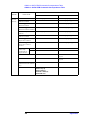
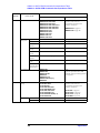
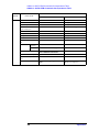
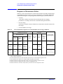
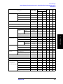
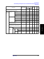
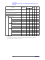
F. List of Responses to Measurement Failure
Responses to Measurement Failure . . . . . . . . . . . . . . . . . . . . . . . . . . . . . . . . . . . . . . . . . . . . . . . . . . . . . . 356
G. Initial Settings
Initial Settings, Settings that can be Saved/Recalled, Settings that can be Backed Up . . . . . . . . . . . . . . . 358
H. Error messages
Order of error number . . . . . . . . . . . . . . . . . . . . . . . . . . . . . . . . . . . . . . . . . . . . . . . . . . . . . . . . . . . . . . . . 366
12
1. To Make the Effective Use
of This Manual
1
To Make Effective Use of This Manual
This chapter provides an overview of this manual as well as useful information to help you
navigate through the manual. It also briefly describes how to use this manual, focusing on
how you can look up particular commands.
13
To Make Effective Use of This Manual
Contents of This Manual
Contents of This Manual
This manual is a programming guide for the Agilent 4287A RF LCR meter. In addition to
explanations of how to remotely control the 4287A from BASIC programs, it provides
listings and in-depth descriptions of sample HP BASIC programs. The chapter-by-chapter
contents of this manual are as follows.
Chapter 1 “To Make Effective Use of This Manual”
This chapter provides an overview of this manual as well as useful information to help
you navigate through the manual. It also briefly describes how to use this manual,
focusing on how you can look up particular commands.
Chapter 2 “Overview of Remote Control”
This chapter gives an overview of the GPIB remote control system and GPIB
commands.
Chapter 3 “Specifying Measurement Conditions”
This chapter explains how to set measurement conditions and configure the
instrument’s display of measurement results.
Chapter 4 “Preparing for Accurate Measurement”
This chapter explains how to carry out calibration, compensation, and test fixture
selection (port extension compensation).
Chapter 5 “Starting Measurement Cycle (Triggering) and Detecting End of
Measurement”
This chapter explains how to trigger the instrument to start a new measurement cycle
and how to detect the end of a measurement cycle.
Chapter 6 “Retrieving Measurement Results”
This chapter explains how to retrieve the results of impedance measurement, test
signal level monitoring, and Rdc measurement. It also describes how the Agilent
4287A internally processes the data.
Chapter 7 “Sorting DUTs Based on Measurement Results”
This chapter explains how to use the bin sorting function to sort DUTs into a number
of configured bins based on measurement results.
Chapter 8 “Statistical Analysis of Measurement Results”
This chapter explains how to use the statistical analysis function.
Chapter 9 “Saving and Recalling Files”
This chapter explains how to save or recall instrument settings and measurement
results to or from a file.
14
Chapter 1
Chapter 10 “Error Handling”
This chapter explains how to handle errors that may occur in the Agilent 4287A while
running a program.
Chapter 11 “Shutting Down the Instrument”
This chapter explains how to shut down the Agilent 4287A.
Chapter 12 “Connecting the Instrument to a Handler with the Handler Interface”
You can use the handler interface of the Agilent 4287A to communicate with an
external handler; for example, the 4287A can send end-of-measurement signals or
bin-sorting results and receive external trigger or key lock signals. This chapter
provides the information needed to set up an auto-sorting system that combines the
4287A with a handler by taking advantage of the handler interface and bin sorting.
Chapter 13 “Using LAN”
This chapter describes LAN (Local Area Network)-based file transfer and remote
control.
Chapter 14 “Using Printer”
This chapter explains how to use a printer to produce hard copies of your
measurement results and images displayed on the LCD screen.
Chapter 15 “Sample Application Programs”
This chapter provides sample measurements (sample programs).
Chapter 16 “Command Reference”
This chapter provides a GPIB command reference for the Agilent 4287A. The
shorthand names of the commands, without the parts that are normally omitted, appear
in alphabetical order in this chapter. If you want to search for commands by their full
names, see “GPIB commands” in the index. If you want to search for commands by
their functionality, see Appendix C, “GPIB Command Table.”
Appendix A “Manual Changes”
This appendix contains the information required to adapt this manual to earlier
versions or configurations of the Agilent 4287A than that indicated by the current
printing date of this manual. The information in this manual applies directly to the
4287A model that has the serial number prefix listed on the title page of this manual.
Appendix B “Status Reporting System”
This appendix describes the status reporting system of the Agilent 4287A.
Appendix C “GPIB Command Table”
This appendix provides the Agilent 4287A GPIB command list sorted according to
function.
Appendix D “GPIB Command Tree”
This appendix provides the Agilent 4287A GPIB command tree.
Chapter 1
15
1. To Make the Effective Use
of This Manual
To Make Effective Use of This Manual
Contents of This Manual
To Make Effective Use of This Manual
Contents of This Manual
Appendix E “4286A vs. 4287A GPIB Commands Correspondence Table.”
This appendix gives the correspondence between the Agilent 4287A GPIB commands
and those of the Agilent 4286A.
Appendix F “List of Responses to Measurement Failure”
This appendix summarizes how the Agilent 4287A responds when a measurement
fails (an overloading or exceeding the Rdc limit range is detected).
Appendix G “Initial Settings”
This appendix provides initial settings, settings that can be saved/recalled, and settings
that can be backed up.
Appendix H “Error messages”
The Agilent 4287A provides error messages to indicate its operating status. This
appendix describes the error messages of the 4287A in order of error number. To
search error messages alphabetically, refer to the Operation Manual.
16
Chapter 1
How To Use This Manual
Chapters 3 to 11 provide task-based descriptions of GPIB commands that are useful for
programming and explain how you can utilize them. These chapters contain explanations
and sample program listings that you can use to develop your custom programs. For more
information on individual commands, see Chapter 16 “Command Reference.”
Looking up GPIB commands
Chapter 16, “Command Reference,” contains a complete reference of GPIB commands.
You can look up a particular GPIB command in any of the following ways:
Lookup by Abbreviated Command Name
The command reference is organized alphabetically according to the
abbreviated name used as the title of each command.
Lookup by Full Command Name
You can use the index at the end of the manual to find full command
names along with the page numbers where they appear.
Lookup by Command Function
Appendix C , “GPIB Command Table,” provides a complete list of
commands by function and indicates the page numbers where the
commands appear in the command reference.
NOTE
Some GPIB commands supported by the 4287A have optional syntax elements. In the
command reference conventions, these elements are enclosed between square brackets ([ ])
or printed in lowercase letters. See “Syntax” on page 202 for more information.
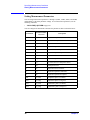
Using sample programs
This manual comes with a sample program disk, which contains the source files of sample
programs used in the manual. The disk is DOS-formatted and the files are saved in the
ASCII format.
Loading a sample program
To load a sample program into the HP BASIC interpreter, use the GET command. For
example, you can load setup.bas, one of the sample programs, by the following procedure:
In the HP BASIC screen, type the following command and press the Return key.
GET "setup.bas"
Looking up a sample program
To look up the description of a sample program you are interested in, see “Sample
program” in the index.
Chapter 1
17
1. To Make the Effective Use
of This Manual
To Make Effective Use of This Manual
How To Use This Manual
To Make Effective Use of This Manual
How To Use This Manual
18
Chapter 1
2. Overview of Remote Control
2
Overview of Remote Control
This chapter gives an overview of the GPIB remote control system and GPIB commands.
19
Overview of Remote Control
Setting Up a GPIB Remote Control System
Setting Up a GPIB Remote Control System
This section describes how to set up a GPIB remote control system.
What is GPIB?
GPIB (General Purpose Interface Bus) is an interface standard for connecting a computer
with peripherals. It complies with these international standards: IEEE 488.1, IEC-625,
IEEE 488.2, and JIS-C1901. With the GPIB interface, you can set up a GPIB remote
control system in which an external computer remotely controls the Agilent 4287A by
sending commands to and receiving data from the unit through the GPIB bus.
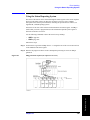
How to set up a GPIB remote control system
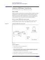
Use GPIB cables to connect the 4287A to an external controller (computer) and any
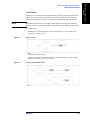
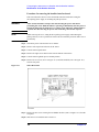
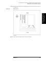
necessary peripherals. Figure 2-1 shows a typical GPIB remote control system.
Figure 2-1
Setting up a GPIB remote control system
Required equipment
1. 4287A with accessories for measuring DUTs
2. External controller (computer)
The external controller can be any personal computer or workstation with a GPIB
interface card and the appropriate software (such as HP BASIC for Windows) for
controlling the instrument via the GPIB interface.
3. Other hardware as needed (extra instruments and/or peripherals)
4. GPIB cables for connecting the 4287A to the external controller and other hardware
20
Chapter 2
Overview of Remote Control
Setting Up a GPIB Remote Control System
Possible sizes and configurations of your remote control system
One GPIB system can host up to 15 devices.
•
Device-to-device cables should be no longer than 4 m. The total length of connection
cables used in one GPIB system should not exceed 2 m ´ N, where N is the number of
connected devices (including controller). In any case, do not construct a system whose
total cable length exceeds 20 m.
•
Do not connect any single device with more than four connectors. Doing so exposes the
connectors to excessive strain, possibly causing a failure.
•
The topology of device connections can be star, linear, or a combination of them. Loop
connections are not supported.
Device selector
Each device is assigned a unique identifier called the “device selector.” When the
controller attempts to control (communicate messages with) one of the devices connected
over the GPIB remote control system, it selects that device with the appropriate device
selector.
A device selector consists of a select code (normally 7) and a GPIB address. For example,
when the select code is 7 and the GPIB address is 17, the device selector is 717. The select
code is system-global. Each device in the same system is assigned a GPIB address that
uniquely identifies it. When this document refers to a device selector in descriptive text or
sample programs, it is always assumed to be 717. Use the following procedure to set the
GPIB address of the 4287A.
Setting the GPIB address (17) for the Agilent 4287A
Step 1. Press the [System] key on the front panel.
Step 2. From the softkey menu along the right-hand edge of the screen, select the softkey labeled
GPIB ADDR [XX] (where XX indicates the current address) by pressing the
key. Then, press the
or
key.
Step 3. When you see the GPIB address entry screen, enter the address (17) by pressing [1] and [7]
on the numeric keypad. Then press the [´1] key or the
Chapter 2
key.
21
2. Overview of Remote Control
•
Overview of Remote Control
Sending GPIB Command Messages
Sending GPIB Command Messages
Types and structure of GPIB commands
GPIB commands available with the 4287A can be divided into two groups:
4287A specific commands
These commands are specific to the 4287A. They provide access to all measurement
features and some generic features built into the 4287A. Commands in this group have a
hierarchical (multi-level) structure called the “command tree” (see Appendix D, “GPIB
Command Tree”). Each command consists of multi-level strings (mnemonics) and colons
(:) that delimit the levels of the hierarchy.
IEEE common commands
These are commands that provide access to generic features defined by IEEE488.2. They
are accepted by any instrument that complies with IEEE488.2. Each command in this
group is prefixed with an asterisk (*). These commands have no hierarchical levels.
Command tree concept
The topmost command in the command tree is referred to as the “root command,” or
simply the “root.” To access a lower-level command in the command tree, you must
specify the appropriate path, which looks like a directory path in the DOS file system.
Turning on the power or resetting the instrument changes the current path to the root. Also,
different path settings are used depending on the special symbols contained in messages:
Message terminators
When a message terminator such as <new line> is detected, the current
path is set to the root.
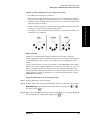
Colons (:)
When a colon is detected between two command mnemonics, the
current path is changed to the next lower level. When a colon is
detected at the beginning of a command, the command mnemonic that
follows is specified as the root level command.
Semicolons (;)
A semicolon is used to delimit two commands contained in the same
message without changing the current path.
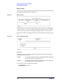
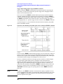
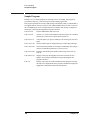
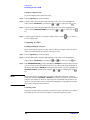
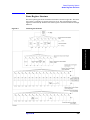
Figure 2-2 illustrates how colons and semicolons can be used to efficiently access various
commands in the command tree.
22
Chapter 2
Overview of Remote Control
Sending GPIB Command Messages
Figure 2-2
Using colons and semicolons
2. Overview of Remote Control
Message syntax
This section describes the syntax for sending program messages via GPIB. Program
messages are sent by the user from an external controller to the instrument to control the
instrument. A program message contains one or more commands along with any required
parameters.
Case sensitivity
Program messages are not case sensitive.
Program message terminators
A program message must be terminated with one of three program message terminators:
<new line>, <^END>, or <new line><^END>. The <^END> terminator ensures that the
immediately preceding data byte is sent out and that EOI is set to the active level on the
GPIB interface. For example, the OUTPUT command (HP BASIC) automatically sends a
message terminator following the last data byte.
Parameters
You must put a space character (ASCII code 32) between the command and the first
parameter. When you send a command with two or more parameters, you must delimit the
parameters with commas (,).
Multi-command messages
When you send a message that contains two or more commands, you must delimit the
commands with semicolons (;). The following HP BASIC example shows how to send a
message that contains *CLS and :INIT commands.
OUTPUT 717;"*CLS;:INIT"
Chapter 2
23
Overview of Remote Control
Sending GPIB Command Messages
Remote mode
The 4287A does not have a remote mode. Therefore, the 4287A is not automatically set to
the remote mode when it receives a GPIB command. Furthermore, there is no local key to
clear the remote mode on the 4287A’s front panel.
Use the key lock function to prevent mis-input from the front panel keys. To lock the front
panel, the keyboard or the mouse, use the following commands.
•
:SYST:KLOC on page 305
•
:SYST:KLOC:KBD on page 305
•
:SYST:KLOC:MOUS on page 306
24
Chapter 2
3. Specifiying Measurement
Conditions
3
Specifying Measurement Conditions
This chapter explains how to set measurement conditions and configure the instrument’s
display of measurement results.
25
Specifying Measurement Conditions
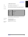
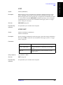
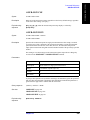
Setting Measurement Parameters
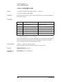
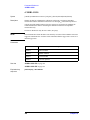
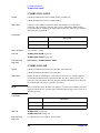
Setting Measurement Parameters
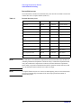
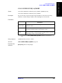
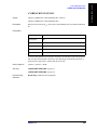
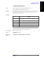
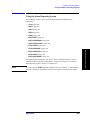
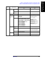
You can assign measurement parameters 1 through 4 (:PAR1, :PAR2, :PAR3, and :PAR4)
independently of the other parameter settings. To set measurement parameters, use the
following command:
:CALC:PAR{1-4}:FORM on page 230
•
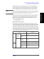
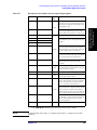
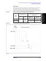
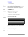
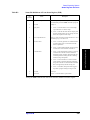
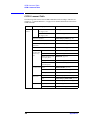
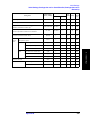
You can configure the instrument to measure the parameters shown in the table below:
Parameter
Parameter label
on screen
Description
Z
|Z|
Impedance amplitude (absolute value)
Y
|Y|
Admittance amplitude (absolute value)
LS
Ls
Equivalent series inductance
LP
Lp
Equivalent parallel inductance
CS
Cs
Equivalent series capacitance
CP
Cp
Equivalent parallel capacitance
RS
Rs
Equivalent series resistance
RP
Rp
Equivalent parallel resistance
Q
Q
Q value (inverse of dissipation factor)
D
D
Dissipation factor
X
X
Equivalent series reactance
G
G
Equivalent parallel conductance
B
B
Equivalent parallel susceptance
TZR
qz (rad)
Impedance phase (in radians)
TZD
qz (deg)
Impedance phase (in degrees)
TYR
qy (rad)
Admittance phase (in radians)
TYD
qy (deg)
Admittance phase (in degrees)
26
Chapter 3
Specifying Measurement Conditions
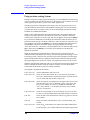
Setting Measurement Point Setup Tables (Signal Source and Averaging
Factor)
Setting Measurement Point Setup Tables (Signal Source and
Averaging Factor)
You can use up to eight measurement point setup tables (Tables 1 through 8) to define the
signal source frequency and averaging factor for each measurement point. Each
measurement point setup table can contain up to 32 measurement points.
When you set measurement points, new settings are applied to the active table. To
configure the active table, use the following command:
•
:SOUR:LIST:TABL on page 297
When you manually configure a measurement point setup table, you must add each
measurement point to the table and define the various conditions that apply to the specific
measurement point. On the other hand, when you use an external controller to configure a
measurement point setup table, you can use the following command to define all the
measurement points in the active table at once:
•
:SOUR:LIST on page 294
•
:SOUR:UNIT on page 298
To change only the averaging factor after completion of calibration/compensation, you
may execute the :SOUR:LIST command by specifying the parameter so that only the
averaging factor will change with the frequency and signal source level identical to the
current settings. In this case, calibration and compensation will be turned off automatically;
you will need to rerun calibration and compensation.
If you need to change only the averaging factor after completion of calibration or
compensation, use the following command:
•
:AVER:COUN on page 210
Execution of the :AVER:COUN command does not turn off calibration or compensation
automatically.
To delete all entries from each table, issue the following command:
•
NOTE
:SOUR:LIST:CLE on page 295
Issuing this command initializes all of the tables (Tables 1 through 8), regardless of which
table is currently active.
To check the number of measurement points defined in the active table, use the following
command:
•
:SOUR:LIST:SIZE? on page 296
Chapter 3
27
3. Specifiying Measurement
Conditions
You can use the following command to set the unit for the signal source level:
Specifying Measurement Conditions
Choosing Whether to Measure the DUT at a Single Point or Multiple Points
Choosing Whether to Measure the DUT at a Single Point or
Multiple Points
Before starting a measurement session with the 4287A, you need to choose whether to
measure the DUT at all points defined in the table or at a single point, that is, list
measurement versus single-point measurement. To make this selection, use the following
command:
•
:SOUR:LIST:STAT on page 297
When you choose single-point measurement, you must specify the measurement point,
which must be one of the measurement points defined in the active table. To specify the
single measurement point, use the following command:
•
:SOUR:LIST:POIN on page 295
Configuring the Instrument for Rdc Measurement
Turning on/off the Rdc measurement function
To specify whether to perform Rdc measurement, use the following command:
•
:SOUR:LIST:RDC on page 296
When the bin sorting function is enabled, turning on Rdc measurement enables the test
function that determines whether the result of Rdc measurement falls within the limit range.
Turning on/off the offset cancel function
You can instruct the instrument to turn on or off the offset cancel function by using the
following command:
•
NOTE
:SOUR:LIST:RDC:OFSC on page 296
To use the offset cancel function, turn ON the offset cancel function before measuring
calibration/compensation data.
Setting the limit range for Rdc measurement
To set a limit range for Rdc measurement, use the following command:
•
28
:CALC:COMP:RDC:LIM on page 224
Chapter 3
Specifying Measurement Conditions
Setting How the Instrument Displays Measurement Results
(Enabling/Disabling Deviation Measurement Mode)
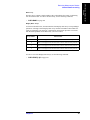
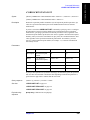
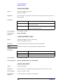
Setting How the Instrument Displays Measurement Results
(Enabling/Disabling Deviation Measurement Mode)
You can have the instrument display measurement results as absolute values or as
deviations relative to the reference value (deviation measurement mode). You can change
this setting for each of the measurement parameters 1 through 4 (:PAR1 through :PAR4).
To make this selection, use the following command:
•
:CALC:PAR{1-4}:EXPR:STAT on page 229
In deviation mode, you can set the instrument to display deviations as they are or as
percentages relative to the reference value. To make this selection, use the following
command:
•
:CALC:PAR{1-4}:EXPR:NAME on page 229
To set the reference value for deviation mode, use the following command:
•
:CALC:PAR{1-4}:EXPR:CENT on page 228
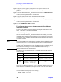
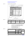
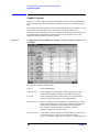
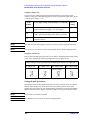
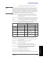
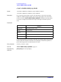
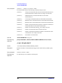
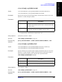
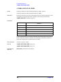
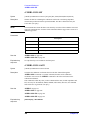
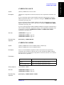
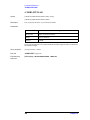
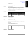
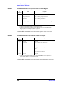
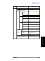
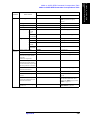
Setting with the
:CALC:PAR{1-4}:EXPR:STAT command
OFF or 0
Setting with the
:CALC:PAR{1-4}:EXPR:NAME
command
———
DEV
How measurement results are displayed
Meas
Meas – Ref
ON or 1
PCNT
Meas – Ref
---------------------------- ´ 100
Ref
where Meas and Ref mean the following:
Meas : Measured value
Ref : Reference value (set with the :CALC:PAR{1-4}:EXPR:CENT command)
NOTE
When you use a GIPB command, such as the :FETC? command on page 280, to retrieve
measurement values, the above settings are applied to the values displayed on screen.
When you are testing DUTs while using the bin sorting function, the instrument always
displays measurement results as they are, regardless of the above settings. See Figure 6-5,
“4287A's data processing flow,” on page 77.
Chapter 3
29
3. Specifiying Measurement
Conditions
How the instrument displays measurement results differs according to the settings made
with the above two commands, as summarized in the table below.
Specifying Measurement Conditions
Configuring Screen Display
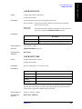
Configuring Screen Display
Configuring the display of measurement results
Showing/hiding all measurement results
You can instruct the instrument to show or hide the entire set of measurement results,
which includes the measurement results for measurement parameters 1 through 4, test
signal level monitoring, and Rdc measurement). To do so, use the following command:
•
:DISP:TEXT1 on page 269
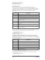
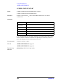
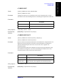
Configuring the display of Individual values
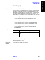
You can set the following display attributes for each value:
•
Number of digits
•
Whether to fix the decimal point
•
Most significant digit when the value is displayed with the decimal point fixed
•
Whether to show or hide the value
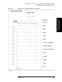
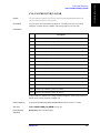
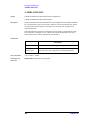
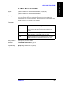
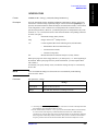
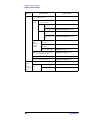
To set the above display attributes, use the commands listed in the table below.
Results for measurement
parameters
:CALC1: parameter 1
:CALC2: parameter 2
:CALC3: parameter 3
:CALC4: parameter 4
Result of test signal level
monitoring
:CALC11: current level
:CALC12: voltage level
Result of Rdc measurement
Number of digits :DISP:TEXT1:CALC{1-4}:DIG
on page 270
:DISP:TEXT1:CALC{11-12}:DIG
on page 272
:DISP:TEXT1:CALC13:DIG
on page 274
Whether to fix
decimal point
:DISP:TEXT1:CALC{1-4}:FIX
on page 271
:DISP:TEXT1:CALC{11-12}:FIX
on page 273
:DISP:TEXT1:CALC13:FIX
on page 274
Most significant
digit when
decimal point is
fixed
:DISP:TEXT1:CALC{1-4}:MSD :DISP:TEXT1:CALC{11-12}:MSD :DISP:TEXT1:CALC13:MSD
on page 271
on page 273
on page 275
Whether to show :DISP:TEXT1:CALC{1-4} on
or hide value
page 270
:DISP:TEXT1:CALC{11-12} on
page 272
:SOUR:LIST:RDC on
page 296*1
*1.This command not only sets whether to show or hide the result of Rdc measurement but also whether
to turn on or off the Rdc measurement function. You cannot use the command to only show or hide the
Rdc result.
30
Chapter 3
Specifying Measurement Conditions
Configuring Screen Display
Setting the display items on the list measurement screen
To define each of the four display items (:LAB1 through :LAB4) that appear on the list
measurement screen, use the following command:
•
:DISP:TEXT2:LAB{1-4} on page 278
Turning on/off the display
You can instruct the instrument to show or hide all of the displayed items except the menu
bar by using the following command:
•
:DISP on page 268
Turning on/off the update of the display
You can instruct the instrument to turn on or off the update of the display by using the
following command:
•
:DISP:UPD on page 279
Turning on/off the backlight of the LCD screen
You can instruct the instrument to turn on or off the backlight of the LCD screen by using
the following command:
•
:DISP:BACK on page 268
If the backlight is off, you cannot read displayed information on the screen.
Showing or hiding the title
To choose whether to show or hide the title display area (the topmost area on the screen),
use the following command:
•
:DISP:TEXT10 on page 276
To define the title string that appears in the title display area, use the following command:
•
:DISP:TEXT10:DATA on page 276
Turning on/off the date display
To choose whether to show or hide the current date and time in the rightmost part of the
status display area, use the following command:
•
:DISP:TEXT11 on page 277
Also, you can choose whether to automatically update the time display in increments of 1
minute as time elapses or keep the day, hour, and minute set to the date/time when you
turned on the display. To make this selection, use the following command:
•
:DISP:TEXT11:MODE on page 277
Chapter 3
31
3. Specifiying Measurement
Conditions
The advantage of the off status is that it allows faster processing speeds of GPIB comannds
than does the on status; on the other hand, its disadvantage is that there is limited update of
the items displayed on the screen.
Specifying Measurement Conditions
Sample Program
Sample Program
Example 3-1 shows a sample program that demonstrates how to configure measurement
conditions. You can find the source file of this program, named setup.bas, on the sample
program disk.
This program resets the instrument and then configures it with the following conditions:
•
Active table number: 3
•
Point number for single-point measurement: 1
•
Measurement point setup table:
•
Point number
Measuring frequency
Averaging factor
Signal source level
1
1 MHz
2
-10 dBm
2
10 MHz
2
-10 dBm
3
100 MHz
2
-10 dBm
4
1 GHz
2
-10 dBm
Settings of Measurement Parameters 1 through 4:
Deviation mode
Parameter
Display
Measurement parameter 1
Ls
Measurement parameter 2
On/off
How parameter is
displayed
Reference
value
On
On
Percentage
100 nH
Rs
On
On
Absolute value
100 nH
Measurement parameter 3
Q
On
Off
——
——
Measurement parameter 4
——
Off
——
——
——
•
List measurement: On
•
Display parameters for list measurement screen
Display item 1: Measuring frequency
Display item 2: Measurement parameter (Ls)
Display item 3: Measurement parameter (Rs)
Display item 4: Measurement parameter (Q)
•
Result of test signal current level monitoring: On
•
Result of test signal voltage level monitoring: On
•
Rdc measurement: On
•
Rdc measurement limit range
Lower limit: -5 W
Upper limit: 5 W
•
Title display area: On (title: "Example 3-1")
•
Time and date display: On (auto update)
32
Chapter 3
Specifying Measurement Conditions
Sample Program
The program is described in detail below:
Sets the GPIB address.
Lines 70 to 100
Stores the active table number, the point number for single-point
measurement, the unit of the signal source level, and the number of
measurement points into the Act_tab, Point_no, Unit$, and Nop
variables, respectively.
Lines 110 to 220
Stores the frequency, averaging factor, and signal source level at each
point into the Freq(*), Ave(*), and Pow(*) variables, respectively.
Lines 230 to 340
Stores the parameter settings, deviation mode settings, and reference
values for measurement parameters 1 through 4 into the Para$(*),
Dev$(*), and Cent(*) arrays, respectively.
Line 350
Stores the on/off setting of list measurement into the List$ variable.
Lines 360 to 390
Stores the parameter selections for display items 1 through 4 on the list
measurement screen into the List_lab$(*) array.
Lines 400 to 410
Stores the on/off settings for the results of test signal current and
voltage monitoring into the Imon_disp$ and Vmon_disp$ variables.
Lines 420 to 440
Stores the on/off setting of Rdc measurement and the upper and lower
limits for the Rdc measurement limit range into the Rdc$, Rdc_l_lim,
and Rdc_u_lim variables, respectively.
Lines 450 to 470
Stores the on/off setting of the title display, title string, and the setting
of the time display into the Title_disp$, Title$, and Clock_disp$
variables, respectively.
Line 490
Resets the instrument.
Lines 530 to 540
Sets the active table number to Act_tab and the unit of the signal
source level to Unit$.
Lines 550 to 590
Configures the measurement point setup table.
Lines 630 to 770
Configures the instrument with the various settings related to
measurement parameters 1 through 4.
Lines 810 to 820
Turns on/off list measurement based on List$ and sets the point
number for single-point measurement to Point_no.
Lines 860 to 870
Turns on/off the results of test signal level current and voltage
monitoring based on Imon_disp$ and Vmon_disp$.
Lines 910 to 920
Turns on/off Rdc measurement based on Rdc$ and set the limit range
for Rdc measurement to the range between Rdc_l_lim and Rdc_u_lim.
Lines 960 to 970
Configures display items 1 through 4 on the list measurement screen.
Lines 1020 to 1030 Turns on/off the title display based on Title_disp$ and sets the title to
Title$.
Lines 1070 to 1120 Configures the date and time display.
Chapter 3
33
3. Specifiying Measurement
Conditions
Line 50
Specifying Measurement Conditions
Sample Program
Example 3-1
Setting Measurement Conditions (setup.bas)
10
20
30
40
50
60
70
80
90
100
110
120
130
140
150
160
170
180
190
200
210
220
230
240
250
260
270
280
290
300
310
320
330
340
350
360
370
380
390
400
410
420
430
440
450
460
470
480
490
500
510
520
530
540
550
560
570
580
590
600
610
34
DIM Unit$[9],List$[9],Rdc$[9],Para$(1:4)[9],Dev$(1:4)[9]
DIM List_lab$(1:4)[9],Title$[30],Title_disp$[9],Clock_disp$[9]
REAL Freq(1:4),Pow(1:4),Cent(1:4),Rdc_l_lim,Rdc_u_lim
INTEGER Ave(1:4),Act_tab,Nop,Point_no,I
ASSIGN @Agt4287a TO 717
!
Act_tab=3
! Active Table Number: 3
Point_no=1
! Selected Point No.: 1
Unit$="DBM"
! Power Level unit: dBm
Nop=4
! Number of Points: 4
Freq(1)=1.0E+6
! Point No.1 Frequency: 1 MHz
Ave(1)=2
!
Averaging Factor: 2
Pow(1)=-10
!
OSC Level: -10 dBm
Freq(2)=1.0E+7
! Point No.2 Frequency: 10 MHz
Ave(2)=2
!
Averaging Factor: 2
Pow(2)=-10
!
OSC Level: -10 dBm
Freq(3)=1.0E+8
! Point No.3 Frequency: 100 MHz
Ave(3)=2
!
Averaging Factor: 2
Pow(3)=-10
!
OSC Level: -10 dBm
Freq(4)=1.0E+9
! Point No.4 Frequency: 1 GHz
Ave(4)=2
!
Averaging Factor: 2
Pow(4)=-10
!
OSC Level: -10 dBm
Para$(1)="LS"
! Measurement
Para.1: Ls
Para$(2)="RS"
!
Parameter
Para.2: Rs
Para$(3)="Q"
!
Para.3: Q
Para$(4)="OFF"
!
Para.4 Display Off
Dev$(1)="PCNT"
! Deviation Mode
Para.1: ON (Pcnt)
Dev$(2)="DEV"
!
Para.2: ON (Dev)
Dev$(3)="OFF"
!
Para.3: OFF
Dev$(4)="OFF"
!
Para.4: OFF
Cent(1)=1.0E-7
! Reference Value
Para.1: 100 nH
Cent(2)=10
!
for Deviation Mode Para.2: 10 ohm
Cent(3)=0
!
Para.3: Dummy
Cent(4)=0
!
Para.4: Dummy
List$="ON"
! List Measurement: ON
List_lab$(1)="FREQ" ! Displayed Parameter
Label-1: Freq.
List_lab$(2)="PAR1" ! for List Measurement
Label-2: Para.1
List_lab$(3)="PAR2" !
Label-3: Para.2
List_lab$(4)="PAR3" !
Label-4: Para.3
Imon_disp$="ON"
! Test Signal
Current Display: On
Vmon_disp$="ON"
!
Level Monitor
Voltage Display: On
Rdc$="ON"
! Rdc Measurement: ON
Rdc_l_lim=-5
! Rdc Measurement
Lower Limit: -0.5 ohm
Rdc_u_lim=5
!
Comparator Function Upper Limit: +0.5 ohm
Title_disp$="ON"
! Title Display Area
Display: On
Title$="Example 3-1" !
Title: "Example 3-1"
Clock_disp$="LIVE"
! Time and Date Display: ON (Live)
!
OUTPUT @Agt4287a;":SYST:PRES"
!
! Measurement Point Setup Table
!
OUTPUT @Agt4287a;":SOUR:LIST:TABL ";Act_tab
OUTPUT @Agt4287a;":SOUR:UNIT "&Unit$
OUTPUT @Agt4287a;":SOUR:LIST ";Nop;",";
FOR I=1 TO Nop-1
OUTPUT @Agt4287a;Freq(I);",";Ave(I);",";Pow(I);",";
NEXT I
OUTPUT @Agt4287a;Freq(Nop);",";Ave(Nop);",";Pow(Nop)
!
! Measurement Parameter
Chapter 3
Specifying Measurement Conditions
Sample Program
!
FOR I=1 TO 4
IF Para$(I)="OFF" THEN
OUTPUT @Agt4287a;":DISP:TEXT1:CALC"&VAL$(I)&" OFF"
ELSE
OUTPUT @Agt4287a;":DISP:TEXT1:CALC"&VAL$(I)&" ON"
OUTPUT @Agt4287a;":CALC:PAR"&VAL$(I)&":FORM "&Para$(I)
IF Dev$(I)="OFF" THEN
OUTPUT @Agt4287a;":CALC:PAR"&VAL$(I)&":EXPR:STAT OFF"
ELSE
OUTPUT @Agt4287a;":CALC:PAR"&VAL$(I)&":EXPR:STAT ON"
OUTPUT @Agt4287a;":CALC:PAR"&VAL$(I)&":EXPR:NAME "&Dev$(I)
OUTPUT @Agt4287a;":CALC:PAR"&VAL$(I)&":EXPR:CENT ";Cent(I)
END IF
END IF
NEXT I
!
! Measurement Point(s)
!
OUTPUT @Agt4287a;":SOUR:LIST:POIN ";Point_no
OUTPUT @Agt4287a;":SOUR:LIST:STAT "&List$
!
! Test Signal Level Monitor Result Display
!
OUTPUT @Agt4287a;":DISP:TEXT1:CALC11 "&Imon_disp$
OUTPUT @Agt4287a;":DISP:TEXT1:CALC12 "&Vmon_disp$
!
! Rdc Measurement
!
OUTPUT @Agt4287a;":SOUR:LIST:RDC "&Rdc$
OUTPUT @Agt4287a;":CALC:COMP:RDC:LIM ";Rdc_l_lim;",";Rdc_u_lim
!
! Displayed Parameter in List Measurement Display
!
FOR I=1 TO 4
OUTPUT @Agt4287a;":DISP:TEXT2:LAB"&VAL$(I)&" "&List_lab$(I)
NEXT I
!
! Title Display Area
!
OUTPUT @Agt4287a;":DISP:TEXT10 "&Title_disp$
OUTPUT @Agt4287a;":DISP:TEXT10:DATA """&Title$&""""
!
! Clock (Data/Time) Display
!
IF Clock_disp$="OFF" THEN
OUTPUT @Agt4287a;":DISP:TEXT11 OFF"
ELSE
OUTPUT @Agt4287a;":DISP:TEXT11 ON"
OUTPUT @Agt4287a;":DISP:TEXT11:MODE "&Clock_disp$
END IF
END
Chapter 3
35
3. Specifiying Measurement
Conditions
620
630
640
650
660
670
680
690
700
710
720
730
740
750
760
770
780
790
800
810
820
830
840
850
860
870
880
890
900
910
920
930
940
950
960
970
980
990
1000
1010
1020
1030
1040
1050
1060
1070
1080
1090
1100
1110
1120
1130
Specifying Measurement Conditions
Sample Program
36
Chapter 3
4. Preparing for Accurate
Measurement
4
Preparing for Accurate Measurement
This chapter explains how to carry out calibration, compensation, and test fixture selection
(port extension compensation).
37
Preparing for Accurate Measurement
Performing Calibration
Performing Calibration
Setting calibration kit values
You can select either the 4287A option 700 (16195B 7-mm calibration kit) or a
user-defined calibration kit. To make this selection, use the following command:
:CORR1:CKIT on page 231
•
If you opt to use a user-defined calibration kit, you need to specify how you define the
calibration kit and then enter the definitions.
Choosing the definition method (fixed or point-by-point)
:CORR1:CKIT:LIST on page 232
•
Entering definitions
To define the OPEN, SHORT, and LOAD standards, use the commands listed in the table
below.
Impedance value
Rdc value
Offset delay time
OPEN
:CORR1:CKIT:STAN1:LIST
on page 235
:CORR1:CKIT:STAN1:DC
on page 233
:CORR1:CKIT:STAN1:EDEL
on page 234
SHORT
:CORR1:CKIT:STAN2:LIST
on page 238
:CORR1:CKIT:STAN2:DC
on page 236
:CORR1:CKIT:STAN2:EDEL
on page 237
LOAD
:CORR1:CKIT:STAN3:LIST
on page 242
:CORR1:CKIT:STAN3:DC
on page 239
:CORR1:CKIT:STAN3:EDEL
on page 240
When you define the impedance value for the LOAD standard, you can choose one of the
available parameter types by using the following command:
•
:CORR1:CKIT:STAN3:FORM on page 241
Measuring data for calculating calibration coefficients and turning on
calibration function
To measure the data for calculating the calibration coefficients, use the following
command:
•
:CORR1:COLL on page 244
This command obtains the data needed for calculating the calibration coefficients for both
impedance and Rdc measurements. If you want to obtain the data for either impedance or
Rdc measurement alone, use one of the following commands instead:
NOTE
•
:CORR1:COLL:RF on page 246
•
:CORR1:COLL:DC on page 245
Issuing the :CORR1:COLL, :CORR1:COLL:RF, or :CORR1:COLL:DC command
does not trigger the instrument to begin data measurement. Therefore, unless the trigger
source is Internal trigger, you must trigger the instrument after issuing the command.
38
Chapter 4
Preparing for Accurate Measurement
Performing Calibration
After obtaining the data for calculating the calibration coefficients for all of the OPEN,
SHORT, and LOAD standards (including the data for both impedance and Rdc
measurements), issue the following command to calculate the calibration coefficients and
turn on the calibration function:
•
NOTE
:CORR1:COLL:SAVE on page 246
You cannot directly turn on or off the calibration function.
Instead, the calibration function is automatically turned on when you issue the
:CORR1:COLL:SAVE command after measuring the data required for calculating the
calibration coefficients.
Also, the calibration function is automatically turned off when you reset the instrument
with the :SYST:PRES command on page 306 or the *RST command on page 206 or
when you configure the measurement point setup table with the :SOUR:LIST command
on page 294.
To check whether the calibration function is currently on or off, use the following
command:
•
:CORR1? on page 231
To define the standard values with the commands described so far, follow these steps:
If you use the same standards for both impedance and Rdc measurements or you omit
Rdc measurement:
Step 1. Connect the OPEN standard and then issue the :CORR1:COLL command, which
designates “STAN1” as the parameter. If the trigger source is not Internal trigger, you must
trigger the instrument after issuing the command. This applies to steps 2 through 4 as well.
Step 2. Connect the S7HORT standard and then issue the :CORR1:COLL command, which
designates “STAN2” as the parameter.
Step 4. To measure a low-loss capacitor, connect the low-loss capacitor and then issue the
:CORR1:COLL or :CORR1:COLL:RF command, which designates “STAN4” as the
parameter.
Step 5. Issue the :CORR1:COLL:SAVE command.
If you use different standards for impedance and Rdc measurements:
Step 1. Connect the OPEN standard for impedance measurement and then issue the
:CORR1:COLL or :CORR1:COLL:RF command, which designates “STAN1” as the
parameter. If the trigger source is not Internal trigger, you must trigger the instrument after
issuing the command. This applies to steps 2 through 7 as well.
Step 2. Connect the SHORT standard for impedance measurement and then issue the
:CORR1:COLL or :CORR1:COLL:RF command, which designates “STAN2” as the
parameter.
Step 3. Connect the LOAD standard for impedance measurement and then issue the
:CORR1:COLL or :CORR1:COLL:RF command, which designates “STAN3” as the
parameter.
Chapter 4
39
4. Preparing for Accurate
Measurement
Step 3. Connect the LOAD standard and then issue the :CORR1:COLL command, which
designates “STAN3” as the parameter.
Preparing for Accurate Measurement
Performing Calibration
Step 4. To measure a low-loss capacitor, connect the low-loss capacitor and then issue the
:CORR1:COLL or :CORR1:COLL:RF command, which designates “STAN4” as the
parameter.
Step 5. Connect the OPEN standard for Rdc measurement and then issue the :CORR1:COLL:DC
command, which designates “STAN1” as the parameter.
Step 6. Connect the SHORT standard for Rdc measurement and then issue the
:CORR1:COLL:DC command, which designates “STAN2” as the parameter.
Step 7. Connect the LOAD standard for Rdc measurement and then issue the :CORR1:COLL:DC
command, which designates “STAN3” as the parameter.
Step 8. Issue the :CORR1:COLL:SAVE command.
Preventing operational errors when measuring data for calculating
calibration coefficients
To retrieve each standard’s measurement data for calculating the calibration coefficients
for Rdc measurement, use the following command:
•
:DATA:RCAD{1-3}? on page 265
Since this command returns the Rdc measurement value for each standard, you can check
whether this value is normal (within the limit range) to prevent operational errors (such as
connecting the wrong standard) that may arise when measuring the data for calculating the
calibration coefficients.
NOTE
The measurement data for the standards cannot be used for evaluating slight differences in
measured values because it is raw measurement data that has not been calibrated and may
differ from the specification value. For example, when the LOAD standard is an inductor,
it exhibits an Rdc value quite similar to that of the SHORT standard; you should be careful
not to inadvertently interchange the LOAD and SHORT standards because they are
difficult to distinguish by their measured values.
The following table provides guidelines for determining the limit range (upper and lower
limits) for testing:
Lower limit (LowerLimit)
Upper limit (UpperLimit)
SHORT
None
UpperLimit = ( Short + Load ) ¤ 2
LOAD
LowerLimit = ( Short + Load ) ¤ 2
1
1
1
------------------------------- = æ ------------- + --------------ö ¤ 2
è Load Openø
UpperLimit
OPEN
1
1
1
------------------------------- = æ ------------- + --------------ö ¤ 2
è Load Openø
LowerLimit
None
In the table above, Short represents the Rdc value for the SHORT standard, Load represents
the Rdc value for the LOAD standard, and Open represents the Rdc value for the OPEN
standard.
For example, when the LOAD standard is a 50 W resistor, the limit ranges for the
respective standards should typically be the following:
SHORT standard: 25 W or lower
40
Chapter 4
Preparing for Accurate Measurement
Performing Calibration
LOAD standard: 25 to 100 W
OPEN standard: 100 W or higher
NOTE
When you validate the Rdc measurement results returned by the :DATA:RCAD{1-3}?
command, you should use the absolute value for the following reasons.
When you measure the SHORT standard, whose resistance is extremely low (nearly zero)
and susceptible to disturbance during measurement, the command may return a small
negative Rdc value. On the other hand, when you measure the OPEN standard, whose
conductance is extremely low (nearly zero) and susceptible to disturbance during
measurement, the command may return a large negative Rdc value (an inverse to a negative
small conductance value).
The measurement data of the respective standards used for calculating the calibration
coefficients for impedance measurement are stored in the calibration data array (see
“Calibration Data Arrays” on page 80). You can retrieve this data with the following
command:
•
:DATA:CAD{1-8}? on page 259
Note that the command shown above returns raw RF measurement data. Unlike DC
measurement, you cannot simply compare the raw RF measurement data with the standard
values to detect operational errors that may have occurred when measuring the calibration
data.
Saving or recalling calibrated state (retrieving or writing calibration
coefficients)
You can retrieve the calibration coefficients and save them to a file. Later, you can retrieve
the calibration coefficients from the file and load them into the 4287A to restore the
calibrated state at the time you saved the file.
The calibration coefficients for impedance measurement are stored in the calibration
coefficient array (see “Calibration Coefficient Arrays” on page 80). To read or write the
calibration coefficient array, use the following command:
:DATA:CCO{1-6} on page 260
To read or write the calibration coefficients for Rdc measurement, use the following
command:
•
NOTE
:DATA:RCCO{1-3} on page 265
When setting calibration coefficients, note the following:
•
•
To ensure that the instrument will provide correct measurement results, you must
configure the instrument to use the same measurement points (point setup table
settings) as when you obtained measurement data for calibration and then set all the
coefficients.
You must turn on the calibration functions before you set the calibration coefficients.
To do so, follow the steps shown in “Measuring data for calculating calibration
coefficients and turning on calibration function” on page 38 before setting the
calibration coefficients. This procedure includes only measuring tentative data and
does not require you to connect the standard before issuing the data measurement
command.
Chapter 4
41
4. Preparing for Accurate
Measurement
•
Preparing for Accurate Measurement
Performing Calibration
Sample program
Example 4-1 shows a sample program that demonstrates how to obtain the measurement
data for calculating the calibration coefficients. You can find the source file of this
program, named calib.bas, on the sample program disk.
The sample program begins by configuring the measurement point setup table and
calibration kit. After measuring the necessary data, it then calculates the calibration
coefficients and turns on the calibration function. Finally, it saves the obtained calibration
coefficients to a file named CAL_DATA.
The program is described in detail below.
Lines 100 to 110
Sets the GPIB address and select code.
Line 120
Stores the name of the calibration coefficients file (CAL_DATA) into
the File$ variable.
Line 130
Resets the instrument.
Line 140
Sets the data transfer format to ASCII.
Lines 180 to 230
Configures the measurement point setup table as follows:
Point
number
Measuring
frequency
Averaging factor
Signal source
level
1
10 MHz
4
0 dBm
2
100 MHz
4
0 dBm
3
1 GHz
4
0 dBm
Line 260
Passes control to a subprogram named Set_cal_kit to configure the
calibration kit.
Lines 290 to 320
Passes control to a subprogram named Inp_data, which prompts the
user to enter the limit values for each standard. Then the program
stores the Rdc measurement lower limit for the OPEN standard into the
Open_l_lim variable, the Rdc measurement upper limit for the SHORT
standard into the Short_u_lim variable, and the Rdc measurement
lower and upper limits for the LOAD standard into the Load_l_lim and
Load_u_lim variables, respectively.
Lines 350 to 420
Passes control to a subprogram named FNCal, which measures the
data for OPEN, SHORT, and LOAD standard.
Lines 440 to 450
Prompts the user to confirm whether to measure a low-loss capacitor
and waits until the user presses the y or n key.
Lines 460 to 490
If the user presses the y key in response to line 450, the program
passes control to the FNCal subprogram to obtain the measurement
data for the low-loss capacitor.
Lines 420 to 440
Calculates the calibration coefficients and turns on the calibration
function.
Lines 570 to 610
Retrieves the number of measurement points and resizes the arrays
Cal_coef_a1, Cal_coef_a2, Cal_coef_b1, Cal_coef_b2, Cal_coef_c1,
and Cal_coef_c2 accordingly.
42
Chapter 4
Preparing for Accurate Measurement
Performing Calibration
Lines 630 to 740
Retrieves the calibration coefficients for impedance measurement, A1,
B1, C1, A2, B2, and C2, and then stores them into the arrays
Cal_coef_a1, Cal_coef_b1, Cal_coef_c1, Cal_coef_a2, Cal_coef_b2,
and Cal_coef_c2, respectively.
Lines 760 to 810
Retrieves the calibration coefficients for Rdc measurement, A, B, and
C, and then stores them into the Cal_coef_dc array, retaining the
original order.
Lines 860 to 880
If File$ matches the name of an existing file, deletes the file.
Lines 890 to 920
Creates a new file using the file name identified by the File$ variable
and saves the data from the arrays Cal_coef_a1, Cal_coef_b1,
Cal_coef_c1, Cal_coef_a2, Cal_coef_b2, Cal_coef_c2, and
Cal_coef_dc to the new file.
Lines 940 to 970
Terminates program after displaying a closing message along with the
name of the file that contains the calibration coefficients.
The FNCal subprogram in lines 1010 to 1680, which measures the data for calculating the
calibration coefficients, is described below.
Lines 1050 to 1060 Retrieves the current trigger source setting and stores the setting into
the Trig_sour$ variable.
Lines 1070 to 1090 After measurement is stopped (the trigger system is stopped), the
program sets the trigger source to GPIB/LAN trigger and turns on the
continuous activation of the trigger system.
Lines 1100 to 1130 Configures the instrument to generate an SRQ upon completion of
measurement.
Lines 1150 to 1160 Prompts the user to set up the connection for measuring the standard
identified by Standard$ and waits until the user presses the y key
followed by the return key.
Lines 1180 to 1200 Clears the status byte register and operation status event register.
Lines 1210 to 1220 Sets the branch target for an SRQ interrupt to enable SRQ interrupts.
Lines 1330 to 1350 Triggers the instrument and waits until the measurement cycle
finishes.
Line 1370
Sets the Err_flag variable to 0.
Lines 1380 to 1540 When the standard is OPEN, SHORT, or LOAD, the subprogram
checks whether the Rdc value falls within the limit range. If the limit
range is exceeded, it sets the Err_flag variable to 1.
Line 1560
If Err_flag is 0, which means that the Rdc value is within the limit
range, the subprogram notifies the user of successful measurement.
Lines 1580 to 1590 If Err_flag is 1, which means that the Rdc value is not within the limit
range, the subprogram notifies the user of failed measurement and
returns to the line where it starts measuring the standard.
Lines 1610 to 1620 Finally, the subprogram returns 0 after restoring the original trigger
source by changing the trigger source to Trig_sour$.
Lines 1640 to 1660 If the key the user pressed in line 1160 is not the y key, this statement
block is executed and the subprogram returns -1.
Chapter 4
43
4. Preparing for Accurate
Measurement
Lines 1230 to 1320 Sends the commands to measure the standard identified by Standard$.
Preparing for Accurate Measurement
Performing Calibration
The Set_cal_kit subprogram in lines 1720 to 2750, which configures the calibration kit, is
described below.
Line 1790
Allows the user to return to the entry start line and re-enter the data if
an error (such as an invalid entry) occurs while entering the number
that identifies the calibration kit.
Lines 1810 to 1840 Displays the list of supported calibration kits and prompts the user to
choose one of the items by typing in the appropriate number.
Line 1850
Converts the entered value into an integer and stores it into the Kit
variable.
Line 1860
If Kit is neither 1 nor 2, the program returns to the entry start line.
Line 1900
If Kit is 1, the program configures the instrument to use the 7 mm
calibration kit.
Line 1920
If Kit is 2, the program configures the instrument to use a user-defined
calibration kit. The description below assumes that Kit is 2.
Lines 1940 to 2020 Displays the list of modes for defining the calibration kit and prompts
the user to choose one of the items by typing in the appropriate
number. Then the program converts the entered value into an integer
and stores it into the Def variable.
Lines 2050 to 2060 If Def is 1, the program configures the instrument so that the user can
define the calibration kit in fixed mode and stores “1” into the Nop
variable, which indicates the number of measurement points that
require definitions.
Lines 2080 to 2100 If Def is 2, the program configures the instrument so that the user can
define the calibration kit in point-by-point mode, and then retrieves the
number of points and stores the number into the Nop variable.
Lines 2130 to 2220 Displays the list of parameter types that can be used to define the
LOAD standard and prompts the user to choose one of the items by
typing in the appropriate number. Then the program converts the
entered value into an integer and stores it into the Load_para variable.
Lines 2230 to 2360 Sets the parameter type for defining the LOAD standard based on
Load_para and stores the parameter names into the Para1$ andPara2$
variables.
Lines 2380 to 2510 Iterates the following steps Nop times.
1. Lines 2390 to 2410: If Nop is 2 or greater, the program displays
each measurement point that requires a definition.
2. Lines 2420 to 2470: Passes control to the Inp_data subprogram to
acquire the OPEN, SHORT, or LOAD standard values from user
input.
3. Lines 2480 to 2500: Configures each standard with the entered
values.
Lines 2530 to 2540 Prompts the user to confirm whether to define the standards for Rdc
measurement and waits until the user presses the y or n key.
Lines 2550 to 2620 If the user presses the y key in response to line 2540, the program
acquires the definitions for Rdc measurement from user input and
configures the standards accordingly.
44
Chapter 4
Preparing for Accurate Measurement
Performing Calibration
Lines 2640 to 2650 Prompts the user to confirm whether to define the delay time and
waits until the user presses the y or n key.
Lines 2660 to 2730 If the user presses the y key in response to line 2650, the program
acquires the delay time from user input and configures the standards
accordingly.
The Inp_data subprogram in lines 2790 to 2900, which lets the user enter the necessary
data, is described below.
Line 2810
Returns to the start line of input if an error occurs due to an invalid
entry or similar reason. This allows the user to make an entry again.
Lines 2830 to 2840 Prompts the user to enter a data value specified by Mes$ and waits
until the user actually enters the value.
Lines 2860 to 2870 Displays the value entered and waits until the user confirms the entry
by pressing the y or n key.
Line 2880
Returns to the entry start line if the key the user pressed in line 2870 is
not the y key.
4. Preparing for Accurate
Measurement
Chapter 4
45
Preparing for Accurate Measurement
Performing Calibration
Example 4-1
Calibration (calib.bas)
10
20
30
40
50
60
70
80
90
100
110
120
130
140
150
160
170
180
190
200
210
220
230
240
250
260
270
280
290
300
310
320
330
340
350
360
370
380
390
400
410
420
430
440
450
460
470
480
490
500
510
520
530
540
550
560
570
580
590
600
610
46
DIM Buff$[9],File$[20],Inp_char$[9]
DIM Cal_coef_a1(1:32,1:2),Cal_coef_a2(1:32,1:2)
DIM Cal_coef_b1(1:32,1:2),Cal_coef_b2(1:32,1:2)
DIM Cal_coef_c1(1:32,1:2),Cal_coef_c2(1:32,1:2)
DIM Cal_coef_dc(1:3)
REAL Open_l_lim,Short_u_lim,Load_l_lim,Load_u_lim
INTEGER Scode,Nop,Result
!
CLEAR SCREEN
ASSIGN @Agt4287a TO 717
Scode=7
File$="CAL_DATA"
OUTPUT @Agt4287a;":SYST:PRES"
OUTPUT @Agt4287a;":FORM ASC"
!---------------------------------------! Measurement Point Setup Table Setting
!---------------------------------------OUTPUT @Agt4287a;":SOUR:LIST:TABL 1"
OUTPUT @Agt4287a;":SOUR:UNIT DBM"
OUTPUT @Agt4287a;":SOUR:LIST 3,";
OUTPUT @Agt4287a;"10E6,4,0,";
OUTPUT @Agt4287a;"100E6,4,0,";
OUTPUT @Agt4287a;"1E9,4,0"
!
PRINT "## Calibration Kit Setting ##"
CALL Set_cal_kit(@Agt4287a)
!
PRINT "## Rdc Limit Setting ##"
CALL Inp_data("Open Lower Limit",Open_l_lim)
CALL Inp_data("Short Upper Limit",Short_u_lim)
CALL Inp_data("Load Lower Limit",Load_l_lim)
CALL Inp_data("Load Upper Limit",Load_u_lim)
!
PRINT "## Measurement ##"
Result=FNCal(@Agt4287a,Scode,"Open",Open_l_lim,1.E+9)
IF Result<>0 THEN Prog_end
!
Result=FNCal(@Agt4287a,Scode,"Short",-1.E+9,Short_u_lim)
IF Result<>0 THEN Prog_end
!
Result=FNCal(@Agt4287a,Scode,"Load",Load_l_lim,Load_u_lim)
IF Result<>0 THEN Prog_end
!
PRINT "Do you want to measure Low Loss Capacitor"
INPUT "[Y]es/[N]o",Inp_char$
IF UPC$(Inp_char$)="Y" OR UPC$(Inp_char$)="YES" THEN
Result=FNCal(@Agt4287a,Scode,"Low Loss C",-1.E+9,1.E+9)
IF Result<>0 THEN Prog_end
END IF
!
OUTPUT @Agt4287a;":CORR1:COLL:SAVE"
OUTPUT @Agt4287a;"*OPC?"
ENTER @Agt4287a;Buff$
!---------------------------------------! Calibration Coefficient Array Reading
!---------------------------------------OUTPUT @Agt4287a;":SOUR:LIST:SIZE?"
ENTER @Agt4287a;Nop
REDIM Cal_coef_a1(1:Nop,1:2),Cal_coef_a2(1:Nop,1:2)
REDIM Cal_coef_b1(1:Nop,1:2),Cal_coef_b2(1:Nop,1:2)
REDIM Cal_coef_c1(1:Nop,1:2),Cal_coef_c2(1:Nop,1:2)
Chapter 4
Preparing for Accurate Measurement
Performing Calibration
Chapter 4
47
4. Preparing for Accurate
Measurement
620
!
630
OUTPUT @Agt4287a;":DATA:CCO1?"
640
ENTER @Agt4287a;Cal_coef_a1(*)
650
OUTPUT @Agt4287a;":DATA:CCO2?"
660
ENTER @Agt4287a;Cal_coef_b1(*)
670
OUTPUT @Agt4287a;":DATA:CCO3?"
680
ENTER @Agt4287a;Cal_coef_c1(*)
690
OUTPUT @Agt4287a;":DATA:CCO4?"
700
ENTER @Agt4287a;Cal_coef_a2(*)
710
OUTPUT @Agt4287a;":DATA:CCO5?"
720
ENTER @Agt4287a;Cal_coef_b2(*)
730
OUTPUT @Agt4287a;":DATA:CCO6?"
740
ENTER @Agt4287a;Cal_coef_c2(*)
750
!
760
OUTPUT @Agt4287a;":DATA:RCCO1?"
770
ENTER @Agt4287a;Cal_coef_dc(1)
780
OUTPUT @Agt4287a;":DATA:RCCO2?"
790
ENTER @Agt4287a;Cal_coef_dc(2)
800
OUTPUT @Agt4287a;":DATA:RCCO3?"
810
ENTER @Agt4287a;Cal_coef_dc(3)
820
!---------------------------------------830
! Calibration Coefficient Saving
840
!---------------------------------------850
Data_size=(Nop*2*6+3)*8
860
ON ERROR GOTO Skip_purge
870
PURGE File$
880 Skip_purge: OFF ERROR
890
CREATE File$,Data_size
900
ASSIGN @File TO File$;FORMAT OFF
910
OUTPUT @File;Cal_coef_a1(*),Cal_coef_b1(*),Cal_coef_c1(*),
Cal_coef_a2(*),Cal_coef_b2(*),Cal_coef_c2(*),Cal_coef_dc(*)
920
ASSIGN @File TO *
930
!
940
PRINT "## Done ##"
950
PRINT "Save file name: "&File$
960
!
970 Prog_end: END
980
!=============================================
990
! Calibration Data Measurement Function
1000
!=============================================
1010 DEF FNCal(@Agt4287a,INTEGER Scode,Standard$,REAL L_lim,REAL U_lim)
1020
DIM Inp_char$[9],Trig_sour$[9],Buff$[9]
1030
REAL Meas_data
1040
INTEGER Err_flag
1050
OUTPUT @Agt4287a;":TRIG:SOUR?"
1060
ENTER @Agt4287a;Trig_sour$
1070
OUTPUT @Agt4287a;":ABOR"
1080
OUTPUT @Agt4287a;":TRIG:SOUR BUS"
1090
OUTPUT @Agt4287a;":INIT:CONT ON"
1100
OUTPUT @Agt4287a;":STAT:OPER:PTR 0"
1110
OUTPUT @Agt4287a;":STAT:OPER:NTR 16"
1120
OUTPUT @Agt4287a;":STAT:OPER:ENAB 16"
1130
OUTPUT @Agt4287a;"*SRE 128"
1140 Cal_meas:!
1150
PRINT "Set "&Standard$&"-Connection."
1160
INPUT "OK? [Y/N]",Inp_char$
1170
IF UPC$(Inp_char$)="Y" THEN
1180
OUTPUT @Agt4287a;"*CLS"
1190
OUTPUT @Agt4287a;"*OPC?"
1200
ENTER @Agt4287a;Buff$
1210
ON INTR Scode GOTO Meas_end
1220
ENABLE INTR Scode;2
1230
SELECT Standard$
1240
CASE "Open"
Preparing for Accurate Measurement
Performing Calibration
1250
1260
1270
1280
1290
1300
1310
1320
1330
1340
1350
1360
1370
1380
1390
1400
1410
1420
1430
1440
1450
1460
1470
1480
1490
1500
1510
1520
1530
1540
1550
1560
1570
1580
1590
1600
1610
1620
1630
1640
1650
1660
1670
1680
1690
1700
1710
1720
1730
1740
1750
1760
1770
1780
1790
1800
1810
1820
1830
1840
1850
1860
1870
1880
48
OUTPUT @Agt4287a;":CORR1:COLL STAN1"
CASE "Short"
OUTPUT @Agt4287a;":CORR1:COLL STAN2"
CASE "Load"
OUTPUT @Agt4287a;":CORR1:COLL STAN3"
CASE "Low Loss C"
OUTPUT @Agt4287a;":CORR1:COLL STAN4"
END SELECT
OUTPUT @Agt4287a;":TRIG"
PRINT "Now measuring..."
Meas_wait: GOTO Meas_wait
Meas_end: OFF INTR Scode
Err_flag=0
SELECT Standard$
CASE "Open"
OUTPUT @Agt4287a;":DATA:RCAD1?"
ENTER @Agt4287a;Rdc
PRINT "Rdc =";ABS(Rdc)
IF ABS(Rdc)<L_lim THEN Err_flag=1
CASE "Short"
OUTPUT @Agt4287a;":DATA:RCAD2?"
ENTER @Agt4287a;Rdc
PRINT "Rdc =";ABS(Rdc)
IF ABS(Rdc)>U_lim THEN Err_flag=1
CASE "Load"
OUTPUT @Agt4287a;":DATA:RCAD3?"
ENTER @Agt4287a;Rdc
PRINT "Rdc =";ABS(Rdc)
IF ABS(Rdc)<L_lim OR ABS(Rdc)>U_lim THEN Err_flag=1
END SELECT
IF Err_flag=0 THEN
PRINT Standard$&" Data Measurement Complete"
ELSE
PRINT "ERROR!!"
GOTO Cal_meas
END IF
OUTPUT @Agt4287a;":TRIG:SOUR "&Trig_sour$
RETURN 0
ELSE
OUTPUT @Agt4287a;":TRIG:SOUR "&Trig_sour$
PRINT "Program Interruption"
RETURN -1
END IF
FNEND
!=============================================
! Calibration Kit Setup Function
!=============================================
SUB Set_cal_kit(@Agt4287a)
DIM Inp_char$[9],Para1$[9],Para2$[9]
INTEGER Def,Nop,Load_para,Point
REAL Open1,Open2,Open_dc,Open_del
REAL Shor1,Shor2,Shor_dc,Shor_del
REAL Load1,Load2,Load_dc,Load_del
!
ON ERROR GOTO Kit_select
Kit_select: !
PRINT "Select Calibration Kit"
PRINT " 1: 7 mm Standard"
PRINT " 2: User Defined"
INPUT "Input 1 or 2",Inp_char$
Kit=IVAL(Inp_char$,10)
IF Kit<1 OR Kit>2 THEN Kit_select
OFF ERROR
!
Chapter 4
Preparing for Accurate Measurement
Performing Calibration
Chapter 4
49
4. Preparing for Accurate
Measurement
1890
IF Kit=1 THEN
1900
OUTPUT @Agt4287a;":CORR1:CKIT DEF"
1910
ELSE
1920
OUTPUT @Agt4287a;":CORR1:CKIT USER"
1930
!
1940
ON ERROR GOTO Def_select
1950 Def_select:!
1960
PRINT "Select Definition Type"
1970
PRINT " 1: Fixed"
1980
PRINT " 2: Not Fixed"
1990
INPUT "Input 1 or 2",Inp_char$
2000
Def=IVAL(Inp_char$,10)
2010
IF Def<1 OR Def>2 THEN Def_select
2020
OFF ERROR
2030
SELECT Def
2040
CASE 1
2050
OUTPUT @Agt4287a;":CORR1:CKIT:LIST OFF"
2060
Nop=1
2070
CASE 2
2080
OUTPUT @Agt4287a;":CORR1:CKIT:LIST ON"
2090
OUTPUT @Agt4287a;":SOUR:LIST:SIZE?"
2100
ENTER @Agt4287a;Nop
2110
END SELECT
2120
!
2130
ON ERROR GOTO Load_select
2140 Load_select:!
2150
PRINT "Select Load Definition Parameters"
2160
PRINT " 1: Rs and Ls"
2170
PRINT " 2: Ls and Q"
2180
PRINT " 3: Cp and D"
2190
INPUT "Input 1 to 3",Inp_char$
2200
Load_para=IVAL(Inp_char$,10)
2210
IF Load_para<1 OR Load_para>3 THEN Load_select
2220
OFF ERROR
2230
SELECT Load_para
2240
CASE 1
2250
OUTPUT @Agt4287a;":CORR1:CKIT:STAN3:FORM RL"
2260
Para1$="Rs"
2270
Para2$="Ls"
2280
CASE 2
2290
OUTPUT @Agt4287a;":CORR1:CKIT:STAN3:FORM LQF"
2300
Para1$="Ls"
2310
Para2$="Q"
2320
CASE 3
2330
OUTPUT @Agt4287a;":CORR1:CKIT:STAN3:FORM CDF"
2340
Para1$="Cp"
2350
Para2$="D"
2360
END SELECT
2370
!
2380
FOR Point=1 TO Nop
2390
IF Nop>1 THEN
2400
PRINT "[Point No."&VAL$(Point)&"]"
2410
END IF
2420
CALL Inp_data("Open(G) Value",Open1)
2430
CALL Inp_data("Open(Cp) Value",Open2)
2440
CALL Inp_data("Short(Rs) Value",Shor1)
2450
CALL Inp_data("Short(Ls) Value",Shor2)
2460
CALL Inp_data("Load("&Para1$&") Value",Load1)
2470
CALL Inp_data("Load("&Para2$&") Value",Load2)
2480
OUTPUT @Agt4287a;":CORR1:CKIT:STAN1:LIST ";Point;",";Open1;","
;Open2
2490
OUTPUT @Agt4287a;":CORR1:CKIT:STAN2:LIST ";Point;",";Shor1;","
;Shor2
2500
OUTPUT @Agt4287a;":CORR1:CKIT:STAN3:LIST ";Point;",";Load1;","
Preparing for Accurate Measurement
Performing Calibration
;Load2
2510
NEXT Point
2520
!
2530
PRINT "Do you want to define standard values for Rdc measurement?"
2540
INPUT "[Y]es/[N]o",Inp_char$
2550
IF UPC$(Inp_char$)="Y" OR UPC$(Inp_char$)="YES" THEN
2560
CALL Inp_data("Open(G) Value for Rdc Measurement",Open_dc)
2570
CALL Inp_data("Short(R) Value for Rdc Measurement",Shor_dc)
2580
CALL Inp_data("Load(R) Value for Rdc Measurement",Load_dc)
2590
OUTPUT @Agt4287a;":CORR1:CKIT:STAN1:DC ";Open_dc
2600
OUTPUT @Agt4287a;":CORR1:CKIT:STAN2:DC ";Shor_dc
2610
OUTPUT @Agt4287a;":CORR1:CKIT:STAN3:DC ";Load_dc
2620
END IF
2630
!
2640
PRINT "Do you want to define standard delay values?"
2650
INPUT "[Y]es/[N]o",Inp_char$
2660
IF UPC$(Inp_char$)="Y" OR UPC$(Inp_char$)="YES" THEN
2670
CALL Inp_data("Open Delay Time",Open_del)
2680
CALL Inp_data("Short Delay Time",Shor_del)
2690
CALL Inp_data("Load Delay Time",Load_del)
2700
OUTPUT @Agt4287a;":CORR1:CKIT:STAN1:EDEL ";Open_del
2710
OUTPUT @Agt4287a;":CORR1:CKIT:STAN2:EDEL ";Shor_del
2720
OUTPUT @Agt4287a;":CORR1:CKIT:STAN3:EDEL ";Load_del
2730
END IF
2740
END IF
2750 SUBEND
2760
!=============================================
2770
! Data Input Function
2780
!=============================================
2790 SUB Inp_data(Mes$,Inp_val)
2800
DIM Inp_char$[30]
2810
ON ERROR GOTO Inp_start
2820 Inp_start:!
2830
PRINT "Input "&Mes$
2840
INPUT "Value?",Inp_char$
2850
Inp_val=VAL(UPC$(Inp_char$))
2860
PRINT "Input Value: ";Inp_val
2870
INPUT "OK? [Y/N]",Inp_char$
2880
IF UPC$(Inp_char$)<>"Y" THEN Inp_start
2890
OFF ERROR
2900 SUBEND
50
Chapter 4
Preparing for Accurate Measurement
Selecting a Test Fixture (Port Extension Compensation)
Selecting a Test Fixture (Port Extension Compensation)
Using port extension compensation function
To compensate for the delay due to the test fixture that holds the DUT (port extension
compensation), you must tell the instrument which test fixture is used in your
measurement. This can be done by selecting data for electrical length compensation, which
is predefined and specific to each test fixture. To specify the test fixture, use the following
command:
•
NOTE
:CORR2:FIXT on page 256
Before running the compensation process, you must specify the fixture or, if using a
custom fixture, set the compensation values for the fixture.
Configuring the instrument to use your custom test fixture
When you use a custom test fixture, you must set the compensation value for the delay due
to the fixture's electrical length. In addtion, you can optionally specify the fixture’s name.
To set the compensation value for the delay due to the fixture's electrical length, use the
following command:
•
:CORR2:FIXT:EDEL:DIST on page 257
If you opt to specify the fixture’s name so that it will be shown on the selection screen
when selecting the test fixture, use the following command:
•
:CORR2:FIXT:LAB on page 258
4. Preparing for Accurate
Measurement
Chapter 4
51
Preparing for Accurate Measurement
Running the Compensation Process
Running the Compensation Process
NOTE
You must turn on the calibration function before using it. In other words, when the
calibration function is off, you cannot perform any of the compensation related operations,
including measuring the data for calculating the compensation coefficients, calculating the
compensation coefficients, turning on or off the compensation function, and retrieving or
setting the compensation coefficients. However, you can configure the compensation kit
even when the calibration function is off.
Setting compensation kit values
You can either use the 4287A's predefined compensation kit values or directly enter other
compensation kit values. To choose how the compensation kit values are defined, use the
following command:
:CORR2:CKIT on page 247
•
If you opt to enter the values, you need to specify how the compensation kit itself is
defined and then enter the definitions.
Choosing definition method (Fixed or Point-by-Point)
:CORR2:CKIT:LIST on page 247
•
Entering definitions
To define the OPEN and SHORT standards, use the commands listed in the following
table:
Impedance value
Rdc value
OPEN
:CORR2:CKIT:STAN1:LIST on page 249
:CORR2:CKIT:STAN1:DC on page 248
SHORT
:CORR2:CKIT:STAN2:LIST on page 251
:CORR2:CKIT:STAN2:DC on page 250
Measuring data for calculating compensation coefficients
To measure the data for calculating the compensation coefficients, use the following
command:
•
:CORR2:COLL on page 252
The command shown above returns the data for calculating the compensation coefficients
for both impedance and Rdc measurements. If you want to obtain the data for either
impedance or Rdc measurement alone, use one of the following commands instead:
NOTE
•
:CORR2:COLL:RF on page 254
•
:CORR2:COLL:DC on page 253
Issuing the :CORR2:COLL, :CORR2:COLL:RF, or :CORR2:COLL:DC command
does not trigger the instrument to begin measuring the data. This means that if the trigger
52
Chapter 4
Preparing for Accurate Measurement
Running the Compensation Process
source is not Internal trigger, you must trigger the instrument after issuing the command.
To define the OPEN and SHORT compensation standards using the commands described
so far, follow these steps:
If you use the same standards for both impedance and Rdc measurements or you omit
Rdc measurement:
Step 1. Connect the OPEN standard and then issue the :CORR2:COLL command, which
designates “STAN1” as the parameter. If the trigger source is not Internal trigger, you must
trigger the instrument after issuing the command. This applies to step 2 as well.
Step 2. Connect the SHORT standard and then issue the :CORR2:COLL command, which
designates “STAN2” as the parameter.
Step 3. Issue the :CORR2:COLL:SAVE command.
If you use different standards for impedance and Rdc measurements:
Step 1. Connect the OPEN standard for impedance measurement and then issue the
:CORR2:COLL or :CORR2:COLL:RF command, which designates “STAN1” as the
parameter. If the trigger source is not Internal trigger, you must trigger the instrument after
issuing the command. This applies to steps 2 through 4 as well.
Step 2. Connect the SHORT standard for impedance measurement and then issue the
:CORR2:COLL or :CORR2:COLL:RF command, which designates “STAN2” as the
parameter.
Step 3. Connect the OPEN standard for Rdc measurement and then issue the :CORR2:COLL:DC
command, which designates “STAN1” as the parameter.
Step 4. Connect the SHORT standard for Rdc measurement and then issue the
:CORR2:COLL:DC command, which designates “STAN2” as the parameter.
Step 5. Issue the :CORR2:COLL:SAVE command.
4. Preparing for Accurate
Measurement
Chapter 4
53
Preparing for Accurate Measurement
Running the Compensation Process
Calculating compensation coefficients and turning on/off compensation
function
After measuring the data for calculating the compensation coefficients, issue the following
commands to calculate the compensation coefficients and turn on the compensation
function:
Measured data
OPEN and SHORT
OPEN only
GPIB command
Status of compensation
function after calculation
OPEN
SHORT
:CORR2:COLL:SAVE on page 255
On
On
:CORR2:COLL:OPEN on page 254*1
On
Unchanged
:CORR2:COLL:SHOR on page 255*1
Unchanged
On
:CORR2:COLL:SAVE on page 255
On
Off
:CORR2:COLL:OPEN on page 254*1
On
Off
:CORR2:COLL:SHOR on page 255
:CORR2:COLL:SAVE on page 255
SHORT only
Not supported
Off
:CORR2:COLL:OPEN on page 254
:CORR2:COLL:SHOR on page 255*1
On
Not supported
Off
On
*1.Issue the command, which designates “ON” (or “1”) as the parameter.
When the OPEN compensation function is currently on, you can issue the
:CORR2:COLL:OPEN command by specifying “OFF” (or “0”) as the parameter to turn
off the OPEN compensation function.
Similarly, when the SHORT compensation function is currently on, you can issue the
:CORR2:COLL:SHOR command by specifying “OFF” (or “0”) as the parameter to turn
off the SHORT compensation function.
Preventing operational errors when measuring data for calculating
compensation coefficients
To retrieve each standard’s measurement data for calculating the compensation coefficients
for Rdc measurement, use the following command:
•
:DATA:RCMD{1-2}? on page 266
Since this command returns the Rdc measurement value (without compensation) for each
of the OPEN and SHORT standards, you can check whether this value is normal to prevent
operational errors (such as connecting the wrong standard) that may arise when measuring
the data.
NOTE
When you validate the Rdc measurement results returned by the command
:DATA:RCMD{1-2}? on page 266, you should use the absolute value for the same
reasons as shown in “Preventing operational errors when measuring data for calculating
calibration coefficients” on page 40.
54
Chapter 4
Preparing for Accurate Measurement
Running the Compensation Process
The measurement data of the OPEN and SHORT standards used for calculating the
compensation coefficients for impedance measurement are stored in the calibration data
array (see “Compensation Data Arrays” on page 81). You can retrieve this data with the
following command:
•
:DATA:CMD{1-2}? on page 261
This command returns RF measurement data without compensation, which require more
complex handling than Rdc values.To detect operational errors that may have occurred
while measuring the compensation data, it is best to use Rdc values instead.
Saving or recalling compensated state (retrieving or writing
compensation coefficients)
You can retrieve the compensation coefficients and save them to a file. Later, you can
retrieve the compensation coefficients from the file and load them into the 4287A to restore
the compensated state at the time you saved the file.
The compensation coefficients for impedance measurement are stored in the compensation
coefficient array (see “Compensation Coefficient Arrays” on page 81). To read or write the
compensation coefficient array, use the following command:
•
:DATA:CMP{1-3} on page 262
To read or write the compensation coefficients for Rdc measurement, use the following
command:
•
NOTE
:DATA:RCMP{1-3} on page 266
When setting compensation coefficients, note these precautions:
To ensure that the instrument will provide correct measurement results, you must
configure the instrument to use the same measurement points (point setup table
settings) as when you obtained measurement data for compensation and turn on the
calibration function before you set the coefficients.
•
You must turn on the compensation function before setting the compensation
coefficients. To do so, follow the steps shown in “Measuring data for calculating
compensation coefficients” on page 52. This procedure includes only measuring
tentative data, and does not require you to connect the standard before issuing the data
measurement command.
Chapter 4
55
4. Preparing for Accurate
Measurement
•
Preparing for Accurate Measurement
Running the Compensation Process
Sample program
Example 4-2 shows a sample program that demonstrates how to obtain the measurement
data for calculating the compensation coefficients. You can find the source file of this
program, named compen.bas, on the sample program disk.
The sample program begins by configuring the measurement point setup table, retrieving
the calibration coefficients determined in Example 4-1 from the file, and configuring the
instrument accordingly. It lets the user select a test fixture and configure the compensation
kit. Finally, it measures the data for calculating the compensation coefficients.
The program is described in detail below.
Lines 100 to 110
Sets the GPIB address and select code.
Line 120
Stores the name of the calibration coefficients file (CAL_DATA) into
the File$ variable.
Lines 130 to 140
Stores the Rdc measurement lower limit for the OPEN standard
(100 W) into the Open_l_lim variable and the Rdc measurement upper
limit for the SHORT standard (25W) into the Short_u_lim variable.
Line 150
Resets the instrument.
Line 160
Sets the data transfer format to ASCII.
Lines 200 to 250
Configures the measurement point setup table as shown below (with
the same settings as Example 4-1).
Point
number
Measuring
frequency
Averaging factor
Signal source
level
1
10 MHz
4
0 dBm
2
100 MHz
4
0 dBm
3
1 GHz
4
0 dBm
Lines 290 to 500
Turns on the calibration function by issuing two commands in
sequence to obtain the calibration data and then calculate the
calibration coefficients. The calibration coefficients acquired here will
be used to overwrite those retrieved from the file (lines 680 to 770) but
will not be used for measurement.
Lines540to580
Retrieves the number of measurement points and resizes the arrays
Cal_coef_a1, Cal_coef_a2, Cal_coef_b1, Cal_coef_b2, Cal_coef_c1,
and Cal_coef_c2 accordingly.
Line 620
Points to the statement block to be executed if an error occurs in
retrieving the calibration coefficients from the file (for example, if no
file matches File$).
Lines 630 to 650
Retrieves the calibration coefficients for impedance measurement, A1,
B1, C1, A2, B2, and C2, as well as those for Rdc measurement, and
then stores them into the arrays Cal_coef_a1, Cal_coef_b1,
Cal_coef_c1, Cal_coef_a2, Cal_coef_b2, Cal_coef_c2, and
Cal_coef_dc, respectively.
Lines 680 to 770
Sets the calibration coefficients.
Line 820
Passes control to a subprogram named Set_fixture, which configures
56
Chapter 4
Preparing for Accurate Measurement
Running the Compensation Process
the test fixture.
Line 850
Passes control to a subprogram named Set_comp_kit to configure the
compensation kit.
Lines 880 to 920
Passes control to a subprogram named FNCompen, which measures
the OPEN and SHORT data.
Lines 940 to 960
Calculates the compensation coefficients and turns on the
compensation function.
Line 980
Displays a closing message.
Lines 1020 to 1050 This statement block is executed if an error occurs in retrieving the
calibration coefficients from the file.
The FNCompen subprogram in lines 1110 to 1690, which measures the data for calculating
the compensation coefficients, is described below.
Lines 1150 to 1160 Retrieves the current trigger source setting, and stores the setting into
the Trig_sour$ variable.
Lines 1170 to 1190 After measurement is stopped (the trigger system is stopped), sets the
trigger source to GPIB/LAN trigger and turns on the continuous
activation of the trigger system.
Lines 1200 to 1230 Configures the instrument to generate an SRQ upon completion of
measurement.
Lines 1250 to 1260 Prompts the user to set up the connection for measuring the standard
identified by Standard$ and waits until the user presses the y key
followed by the return key.
Lines 1280 to 1300 Clears the status byte register and operation status event register.
Lines 1310 to 1320 Sets the branch target for an SRQ interrupt to enable SRQ interrupts.
Lines 1330 to 1380 Sends the commands that measure the standard identified by
Standard$.
Line 1430
Sets the Err_flag variable to 0.
Lines 1440 to 1550 Checks whether the Rdc value falls within the limit range. If the limit
range is exceeded, it sets the Err_flag variable to 1 again.
Line 1570
If Err_flag is 0, which means that the Rdc value is within the limit
range, the subprogram notifies the user of successful measurement.
Lines 1590 to 1600 If Err_flag is 1, which means that the Rdc value is not within the limit
range, the subprogram notifies the user of failed measurement and
returns to the line where it starts measuring the standard.
Lines 1620 to 1630 Finally, The subprogram returns 0 after restoring the original trigger
source by changing the trigger source to Trig_sour$.
Lines 1650 to 1670 If the key the user pressed in line 1260 is not the y key, this statement
block is executed and the subprogram returns -1.
Chapter 4
57
4. Preparing for Accurate
Measurement
Lines 1390 to 1410 Triggers the instrument, and waits until the measurement cycle
finishes.
Preparing for Accurate Measurement
Running the Compensation Process
The Set_comp_kit subprogram in lines 1730 to 2350, which configures the compensation
kit, is described below.
Line 1790
Allows the user to return to the entry start line and re-enter the data if
an error (such as an invalid entry) occurs while entering the number
that identifies the calibration kit definitions (4287A's predefined
values or custom settings).
Lines 1810 to 1840 Displays the list of compensation kit definitions and prompts the user
to choose one of the items by typing in the appropriate number.
Line 1850
Converts the entered value into an integer and stores it into the Kit
variable.
Line 1860
If Kit is neither 1 nor 2, the program returns to the entry start line.
Line 1900
If Kit is 1, the subprogram configures the 4287A to use its built-in
definition for the compensation kit values.
Line 1920
If Kit is 2, the subprogram configures the instrument to use a
user-defined compensation kit. The description below assumes that Kit
is 2.
Lines 1940 to 2020 Displays the list of modes for defining the compensation kit and
prompts the user to choose one of the items by typing in the
appropriate number. Then the program converts the entered value into
an integer and stores it into the Def variable.
Lines 2050 to 2060 If Def is 1, the program configures the instrument so that the user can
define the compensation kit in fixed mode and stores “1” into the Nop
variable, which indicates the number of measurement points that
require definitions.
Lines 2080 to 2100 If Def is 2, the program configures the instrument so that the user can
define the compensation kit in point-by-point mode and then retrieves
the number of points and stores the number into the Nop variable.
Lines 2130 to 2230 Iterates the following steps Nop times.
1. Lines 2140 to 2160: If Nop is 2 or greater, the program displays
each measurement point that requires definition.
2. Lines 2170 to 2200: Passes control to the Inp_data subprogram to
acquire the OPEN and standard values from user input.
3. Lines 2210 to 2220: Configures each standard with the entered
values.
Lines 2250 to 2260 Prompts the user to confirm whether to define the standards for Rdc
measurement and waits until the user presses the y or n key.
Lines 2270 to 2320 If the user presses the y key in response to line 2260, the program
acquires the definitions for Rdc measurement from the user input and
configures the standards accordingly.
58
Chapter 4
Preparing for Accurate Measurement
Running the Compensation Process
The Set_fixture subprogram in lines 2390 to 2820, which configures the test fixture, is
described below.
Line 2440
Allows the user to return to the entry start line and re-enter the data if
an error (such as an invalid entry) occurs while entering the number
that identifies the test fixture.
Lines 2460 to 2560 Displays the list of supported test fixtures and prompts the user to
choose one of the items by typing in the appropriate number.
Line 2570
Converts the entered value into an integer and stores it into the Fixture
variable.
Line 2580
If Fixture is not an integer between 1 and 9, the program returns to the
entry start line.
Lines 2600 to 2810 Configures the test fixture based on Fixture. If Fixture is 9, which
means that the user opted to use a user-defined fixture, the subprogram
acquires the delay compensation value (electrical length) from the user
input and configures the test fixture accordingly.
For more information on the Inp_data subprogram (lines 2860 to 2970), refer to the
description in Example 4-1 on page 46.
4. Preparing for Accurate
Measurement
Chapter 4
59
Preparing for Accurate Measurement
Running the Compensation Process
Example 4-2
Compensation (compen.bas)
10
DIM Buff$[9],File$[20],Inp_char$[9]
20
DIM Cal_coef_a1(1:32,1:2),Cal_coef_a2(1:32,1:2)
30
DIM Cal_coef_b1(1:32,1:2),Cal_coef_b2(1:32,1:2)
40
DIM Cal_coef_c1(1:32,1:2),Cal_coef_c2(1:32,1:2)
50
DIM Cal_coef_dc(1:3)
60
REAL Open_l_lim,Short_u_lim
70
INTEGER Scode,Nop,Result,I
80
!
90
CLEAR SCREEN
100
ASSIGN @Agt4287a TO 717
110
Scode=7
120
File$="CAL_DATA"
130
Open_l_lim=100
140
Short_u_lim=25
150
OUTPUT @Agt4287a;":SYST:PRES"
160
OUTPUT @Agt4287a;":FORM ASC"
170
!---------------------------------------180
! Measurement Point Setup Table Setting
190
!---------------------------------------200
OUTPUT @Agt4287a;":SOUR:LIST:TABL 1"
210
OUTPUT @Agt4287a;":SOUR:UNIT DBM"
220
OUTPUT @Agt4287a;":SOUR:LIST 3,";
230
OUTPUT @Agt4287a;"10E6,4,0,";
240
OUTPUT @Agt4287a;"100E6,4,0,";
250
OUTPUT @Agt4287a;"1E9,4,0"
260
!---------------------------------------270
! Dummy Measurement
280
!---------------------------------------290
OUTPUT @Agt4287a;":ABOR"
300
OUTPUT @Agt4287a;":TRIG:SOUR BUS"
310
OUTPUT @Agt4287a;":INIT:CONT ON"
320
OUTPUT @Agt4287a;":STAT:OPER:PTR 0"
330
OUTPUT @Agt4287a;":STAT:OPER:NTR 16"
340
OUTPUT @Agt4287a;":STAT:OPER:ENAB 16"
350
OUTPUT @Agt4287a;"*SRE 128"
360
FOR I=1 TO 3
370
OUTPUT @Agt4287a;"*CLS"
380
OUTPUT @Agt4287a;"*OPC?"
390
ENTER @Agt4287a;Buff$
400
ON INTR Scode GOTO Dummy_meas_end
410
ENABLE INTR Scode;2
420
OUTPUT @Agt4287a;":CORR1:COLL STAN"&VAL$(I)
430
OUTPUT @Agt4287a;":TRIG"
440 Dummy_meas_wait: GOTO Dummy_meas_wait
450 Dummy_meas_end: OFF INTR Scode
460
NEXT I
470
OUTPUT @Agt4287a;":CORR1:COLL:SAVE"
480
OUTPUT @Agt4287a;"*OPC?"
490
ENTER @Agt4287a;Buff$
500
OUTPUT @Agt4287a;":TRIG:SOUR INT"
510
!---------------------------------------520
! Download Calibration Coeficient
530
!---------------------------------------540
OUTPUT @Agt4287a;":SOUR:LIST:SIZE?"
550
ENTER @Agt4287a;Nop
560
REDIM Cal_coef_a1(1:Nop,1:2),Cal_coef_a2(1:Nop,1:2)
570
REDIM Cal_coef_b1(1:Nop,1:2),Cal_coef_b2(1:Nop,1:2)
580
REDIM Cal_coef_c1(1:Nop,1:2),Cal_coef_c2(1:Nop,1:2)
590
!
600
PRINT "Downloading Calibration Coeficient..."
610
!
60
Chapter 4
Preparing for Accurate Measurement
Running the Compensation Process
Chapter 4
4. Preparing for Accurate
Measurement
620
ON ERROR GOTO File_error
630
ASSIGN @File TO File$
640
ENTER @File;Cal_coef_a1(*),Cal_coef_b1(*),Cal_coef_c1(*),
Cal_coef_a2(*),Cal_coef_b2(*),Cal_coef_c2(*),Cal_coef_dc(*)
650
ASSIGN @File TO *
660
OFF ERROR
670
!
680
OUTPUT @Agt4287a;":DATA:CCO1 ";Cal_coef_a1(*)
690
OUTPUT @Agt4287a;":DATA:CCO2 ";Cal_coef_b1(*)
700
OUTPUT @Agt4287a;":DATA:CCO3 ";Cal_coef_c1(*)
710
OUTPUT @Agt4287a;":DATA:CCO4 ";Cal_coef_a2(*)
720
OUTPUT @Agt4287a;":DATA:CCO5 ";Cal_coef_b2(*)
730
OUTPUT @Agt4287a;":DATA:CCO6 ";Cal_coef_c2(*)
740
!
750
OUTPUT @Agt4287a;":DATA:RCCO1 ";Cal_coef_dc(1)
760
OUTPUT @Agt4287a;":DATA:RCCO2 ";Cal_coef_dc(2)
770
OUTPUT @Agt4287a;":DATA:RCCO3 ";Cal_coef_dc(3)
780
!---------------------------------------790
! Compensation
800
!---------------------------------------810
PRINT "## Test Fixture Setting ##"
820
CALL Set_fixture(@Agt4287a)
830
!
840
PRINT "## Compensation Kit Setup ##"
850
CALL Set_comp_kit(@Agt4287a)
860
!
870
PRINT "## Measurement ##"
880
Result=FNCompen(@Agt4287a,Scode,"Open",Open_l_lim)
890
IF Result<>0 THEN Prog_end
900
!
910
Result=FNCompen(@Agt4287a,Scode,"Short",Short_u_lim)
920
IF Result<>0 THEN Prog_end
930
!
940
OUTPUT @Agt4287a;":CORR2:COLL:SAVE"
950
OUTPUT @Agt4287a;"*OPC?"
960
ENTER @Agt4287a;Buff$
970
!
980
PRINT "## Done ##"
990
GOTO Prog_end
1000
!
1010 File_error:OFF ERROR
1020
PRINT "################## ERROR ##################"
1030
PRINT "The CAL_DATA (cal. coef. file) is NOT exist."
1040
PRINT "
or"
1050
PRINT "The CAL_DATA's size is UNSUITABLE."
1060
!
1070 Prog_end:END
1080
!=============================================
1090
! Compensation Data Measurement Function
1100
!=============================================
1110 DEF FNCompen(@Agt4287a,INTEGER Scode,Standard$,REAL Limit)
1120
DIM Inp_char$[9],Trig_sour$[9],Buff$[9]
1130
REAL Rdc
1140
INTEGER Err_flag
1150
OUTPUT @Agt4287a;":TRIG:SOUR?"
1160
ENTER @Agt4287a;Trig_sour$
1170
OUTPUT @Agt4287a;":ABOR"
1180
OUTPUT @Agt4287a;":TRIG:SOUR BUS"
1190
OUTPUT @Agt4287a;":INIT:CONT ON"
1200
OUTPUT @Agt4287a;":STAT:OPER:PTR 0"
1210
OUTPUT @Agt4287a;":STAT:OPER:NTR 16"
1220
OUTPUT @Agt4287a;":STAT:OPER:ENAB 16"
1230
OUTPUT @Agt4287a;"*SRE 128"
1240 Compen_meas: !
61
Preparing for Accurate Measurement
Running the Compensation Process
1250
1260
1270
1280
1290
1300
1310
1320
1330
1340
1350
1360
1370
1380
1390
1400
1410
1420
1430
1440
1450
1460
1470
1480
1490
1500
1510
1520
1530
1540
1550
1560
1570
1580
1590
1600
1610
1620
1630
1640
1650
1660
1670
1680
1690
1700
1710
1720
1730
1740
1750
1760
1770
1780
1790
1800
1810
1820
1830
1840
1850
1860
1870
1880
62
PRINT "Set "&Standard$&"-Connection."
INPUT "OK? [Y/N]",Inp_char$
IF UPC$(Inp_char$)="Y" THEN
OUTPUT @Agt4287a;"*CLS"
OUTPUT @Agt4287a;"*OPC?"
ENTER @Agt4287a;Buff$
ON INTR Scode GOTO Meas_end
ENABLE INTR Scode;2
SELECT Standard$
CASE "Open"
OUTPUT @Agt4287a;":CORR2:COLL STAN1"
CASE "Short"
OUTPUT @Agt4287a;":CORR2:COLL STAN2"
END SELECT
OUTPUT @Agt4287a;":TRIG"
PRINT "Now measuring..."
Meas_wait: GOTO Meas_wait
Meas_end: OFF INTR Scode
Err_flag=0
SELECT Standard$
CASE "Open"
OUTPUT @Agt4287a;":DATA:RCMD1?"
ENTER @Agt4287a;Rdc
PRINT "Rdc =";ABS(Rdc)
IF ABS(Rdc)<Limit THEN Err_flag=1
CASE "Short"
OUTPUT @Agt4287a;":DATA:RCMD2?"
ENTER @Agt4287a;Rdc
PRINT "Rdc =";ABS(Rdc)
IF ABS(Rdc)>Limit THEN Err_flag=1
END SELECT
IF Err_flag=0 THEN
PRINT Standard$&" Data Measurement Complete"
ELSE
PRINT "ERROR!!"
GOTO Compen_meas
END IF
OUTPUT @Agt4287a;":TRIG:SOUR "&Trig_sour$
RETURN 0
ELSE
OUTPUT @Agt4287a;":TRIG:SOUR "&Trig_sour$
PRINT "Program Interruption"
RETURN -1
END IF
FNEND
!=============================================
! Compensation Kit Setup Function
!=============================================
SUB Set_comp_kit(@Agt4287a)
DIM Inp_char$[30],Para1$[9],Para2$[9]
INTEGER Def,Nop,Load_para,Point
REAL Open1,Open2,Open_dc
REAL Shor1,Shor2,Shor_dc
!
ON ERROR GOTO Kit_select
Kit_select: !
PRINT "Select Compensation Kit Value"
PRINT " 1: Default"
PRINT " 2: User Defined"
INPUT "Input 1 or 2",Inp_char$
Kit=IVAL(Inp_char$,10)
IF Kit<1 OR Kit>2 THEN Kit_select
OFF ERROR
!
Chapter 4
Preparing for Accurate Measurement
Running the Compensation Process
Chapter 4
63
4. Preparing for Accurate
Measurement
1890
IF Kit=1 THEN
1900
OUTPUT @Agt4287a;":CORR2:CKIT DEF"
1910
ELSE
1920
OUTPUT @Agt4287a;":CORR2:CKIT USER"
1930
!
1940
ON ERROR GOTO Def_select
1950 Def_select:!
1960
PRINT "Select Definition Type"
1970
PRINT " 1: Fixed"
1980
PRINT " 2: Not Fixed"
1990
INPUT "Input 1 or 2",Inp_char$
2000
Def=IVAL(Inp_char$,10)
2010
IF Def<1 OR Def>2 THEN Def_select
2020
OFF ERROR
2030
SELECT Def
2040
CASE 1
2050
OUTPUT @Agt4287a;":CORR2:CKIT:LIST OFF"
2060
Nop=1
2070
CASE 2
2080
OUTPUT @Agt4287a;":CORR2:CKIT:LIST ON"
2090
OUTPUT @Agt4287a;":SOUR:LIST:SIZE?"
2100
ENTER @Agt4287a;Nop
2110
END SELECT
2120
!
2130
FOR Point=1 TO Nop
2140
IF Nop>1 THEN
2150
PRINT "[Point No."&VAL$(Point)&"]"
2160
END IF
2170
CALL Inp_data("Open(G) Value",Open1)
2180
CALL Inp_data("Open(Cp) Value",Open2)
2190
CALL Inp_data("Short(Rs) Value",Shor1)
2200
CALL Inp_data("Short(Ls) Value",Shor2)
2210
OUTPUT @Agt4287a;":CORR2:CKIT:STAN1:LIST ";Point;",";Open1;","
;Open2
2220
OUTPUT @Agt4287a;":CORR2:CKIT:STAN2:LIST ";Point;",";Shor1;","
;Shor2
2230
NEXT Point
2240
!
2250
PRINT "Do you want to define standard values for Rdc measurement?"
2260
INPUT "[Y]es/[N]o",Inp_char$
2270
IF UPC$(Inp_char$)="Y" OR UPC$(Inp_char$)="YES" THEN
2280
CALL Inp_data("Open(G) Value for Rdc Measurement",Open_dc)
2290
CALL Inp_data("Short(R) Value for Rdc Measurement",Shor_dc)
2300
OUTPUT @Agt4287a;":CORR2:CKIT:STAN1:DC ";Open_dc
2310
OUTPUT @Agt4287a;":CORR2:CKIT:STAN2:DC ";Shor_dc
2320
END IF
2330
END IF
2340
!
2350 SUBEND
2360
!=============================================
2370
! Test Fixture Setting Function
2380
!=============================================
2390 SUB Set_fixture(@Agt4287a)
2400
DIM Inp_char$[30]
2410
INTEGER Fixture
2420
REAL E_len
2430
!
2440
ON ERROR GOTO Fixture_select
2450 Fixture_select: !
2460
PRINT "Select Test Fixture"
2470
PRINT " 1: None"
2480
PRINT " 2: 16191A"
2490
PRINT " 3: 16192A"
2500
PRINT " 4: 16193A"
Preparing for Accurate Measurement
Running the Compensation Process
2510
2520
2530
2540
2550
2560
2570
2580
2590
2600
2610
2620
2630
2640
2650
2660
2670
2680
2690
2700
2710
2720
2730
2740
2750
2760
2770
2780
2790
2800
2810
2820
2830
2840
2850
2860
2870
2880
2890
2900
2910
2920
2930
2940
2950
2960
2970
64
PRINT " 5: 16194A"
PRINT " 6: 16196A"
PRINT " 7: 16196B"
PRINT " 8: 16196C"
PRINT " 9: USER"
INPUT "Input 1 to 9",Inp_char$
Fixture=IVAL(Inp_char$,10)
IF Fixture<1 OR Fixture>8 THEN Fixture_select
OFF ERROR
SELECT Fixture
CASE 1
OUTPUT @Agt4287a;":CORR2:FIXT NONE"
CASE 2
OUTPUT @Agt4287a;":CORR2:FIXT FXT16191A"
CASE 3
OUTPUT @Agt4287a;":CORR2:FIXT FXT16192A"
CASE 4
OUTPUT @Agt4287a;":CORR2:FIXT FXT16193A"
CASE 5
OUTPUT @Agt4287a;":CORR2:FIXT FXT16194A"
CASE 6
OUTPUT @Agt4287a;":CORR2:FIXT FXT16196A"
CASE 7
OUTPUT @Agt4287a;":CORR2:FIXT FXT16196B"
CASE 8
OUTPUT @Agt4287a;":CORR2:FIXT FXT16196C"
CASE 9
OUTPUT @Agt4287a;":CORR2:FIXT USER"
CALL Inp_data("Electrical Length of the User Fixture",E_len)
OUTPUT @Agt4287a;":CORR2:FIXT:EDEL:DIST ";E_len
END SELECT
SUBEND
!=============================================
! Data Input Function
!=============================================
SUB Inp_data(Mes$,Inp_val)
DIM Inp_char$[30]
ON ERROR GOTO Inp_start
Inp_start:!
PRINT "Input "&Mes$
INPUT "Value?",Inp_char$
Inp_val=VAL(UPC$(Inp_char$))
PRINT "Input Value: ";Inp_val
INPUT "OK? [Y/N]",Inp_char$
IF UPC$(Inp_char$)<>"Y" THEN Inp_start
OFF ERROR
SUBEND
Chapter 4
5
Starting Measurement Cycle (Triggering)
and Detecting End of Measurement
65
5. Starting Measurement
Cycle (Triggering) and Detecting
End of Measurement
This chapter explains how to trigger the instrument to start a new measurement cycle and
how to detect the end of a measurement cycle.
Starting Measurement Cycle (Triggering) and Detecting End of Measurement
Starting a New Measurement Cycle (Triggering)
Starting a New Measurement Cycle (Triggering)
Trigger system
The trigger system is responsible for such tasks as detecting the start of a measurement
cycle (triggering) and controlling the pre-measurement delay time. As shown in Figure 5-1,
the trigger system has three states: Idle, Waiting for Trigger, and Measurement.
Figure 5-1
Trigger system
The following subsections describe each state and how the trigger system switches among
the three states.
Idle state
The trigger system is put into Idle state (arrow e in Figure 5-1) when you power on the
instrument or issue one of the following commands:
•
*RST on page 206
•
:ABOR on page 209
The trigger system is put into Waiting for Trigger state (arrow a in Figure 5-1) when you
activate it with one of the following commands:
•
:INIT on page 287
•
:INIT:CONT on page 287 (“ON” specified)
66
Chapter 5
Starting Measurement Cycle (Triggering) and Detecting End of Measurement
Starting a New Measurement Cycle (Triggering)
Waiting for Trigger state (Trigger Event Detect state)
The trigger system is put into Measurement state (arrow b in Figure 5-1) after the elapse of
the trigger delay time (set with the :TRIG:DEL command on page 308) if the instrument is
triggered (a trigger is detected) or the :TRIG command on page 308 is issued while the
trigger system is in Waiting for Trigger state.
As shown in the table below, how the instrument is triggered differs depending on which
trigger source is specified. To specify the trigger source, use the :TRIG:SOUR command
on page 310.
Trigger source
Figure 5-2
How the instrument is triggered
Internal trigger
The instrument is automatically triggered within itself.
External trigger
The instrument is triggered when a trigger signal is input through
the Ext TRIGGER terminal or handler interface.
GPIB/LAN trigger
(Bus)
The instrument is triggered when the *TRG command on
page 208 or TRGGER command of HP BASIC is issued.
Manual trigger
The instrument is triggered when the [Trigger] key on the front
panel is pressed.
Transition from Waiting for Trigger state to Measurement state
67
5. Starting Measurement
Cycle (Triggering) and Detecting
End of Measurement
Chapter 5
Starting Measurement Cycle (Triggering) and Detecting End of Measurement
Starting a New Measurement Cycle (Triggering)
Measurement state (sequence operation state)
In Measurement state, the trigger system waits until the measurement point delay time (set
with the :TRIG:SEQ2:DEL command on page 309) elapses and then starts measurement
for each measurement point.
When the instrument has finished measuring the DUT at the single specified point (for
single-point measurement) or at all the points defined in the active table (for list
measurement), the trigger system switches to either Idle or Waiting for Trigger state
depending on whether continuous activation is off or on (set with the :INIT:CONT
command on page 287):
If continuous activation is off:
Switches to Idle state (arrow c in Figure 5-1).
If continuous activation is on:
Switches to Waiting for Trigger state (arrow d in Figure 5-1).
68
Chapter 5
Starting Measurement Cycle (Triggering) and Detecting End of Measurement
Starting a New Measurement Cycle (Triggering)
Starting a measurement cycle (Triggering the instrument)
Configuring the instrument to automatically perform continuous measurement
(initial setting):
Step 1. Issue the :TRIG:SOUR command on page 310 to set the trigger source to Internal trigger.
Step 2. If the trigger system is in Idle state (that is, it is not currently active), issue the
:INIT:CONT command on page 287 to turn on continuous activation of the trigger system.
Starting measurement on demand:
1) To trigger the instrument on demand, follow the steps below.
Step 1. Issue the :TRIG:SOUR command on page 310 to set the trigger source to GPIB/LAN
trigger.
Step 2. If the trigger system is in Idle state (that is, it is not currently active), issue the
:INIT:CONT command to turn on continuous activation of the trigger system.
Step 3. Trigger the instrument whenever you want to perform measurement. An external controller
can trigger the instrument with one of the following two commands:
Command
Applicable
trigger source
Query response
*TRG on page 208
Yes (returns measurement results)
GPIB/LAN trigger
:TRIG on page 308
No
All
Step 4. To start the next measurement cycle, repeat step 3.
2) To activate the trigger system on demand, follow the steps below.
Step 1. If the trigger system is active (that is, not in Idle state), issue the :ABOR command on
page 209 to stop the trigger system.
Step 2. Issue the :TRIG:SOUR command on page 310 to set the trigger source to Internal trigger.
Step 3. You can activate the trigger system using the :INIT command on page 287 at any time.
Consequently, the instrument will be automatically triggered by Internal trigger and
perform one measurement cycle.
Step 4. To start the next measurement cycle, repeat step 3.
69
5. Starting Measurement
Cycle (Triggering) and Detecting
End of Measurement
Chapter 5
Starting Measurement Cycle (Triggering) and Detecting End of Measurement
Waiting for (Detecting) End of Measurement
Waiting for (Detecting) End of Measurement
The status of the 4287A can be detected through the status registers. This section describes
how to detect the end of measurement by using the status registers. For a complete
description of the status report mechanism, including the specifications of each bit, see
Appendix B, “Status Reporting System.”
End of measurement is reported by the operation status condition register. An SRQ (service
request) is useful when you create a program that uses the information reported by this
register to detect the end of measurement.
To detect the end of measurement via an SRQ, use one of the following commands:
•
*SRE on page 207
•
:STAT:OPER:ENAB on page 299
•
:STAT:OPER:PTR on page 300
•
:STAT:OPER:NTR on page 300
Follow these steps:
Step 1. Configure the 4287A to generate an SRQ when the bit 4 value of the operation status
condition register is changed form 1 to 0.
Step 2. Trigger the instrument to start a measurement cycle.
Step 3. When an SRQ is generated, the program interrupts the measurement cycle.
Figure 5-3
SRQ generation sequence (at end of list measurement)
70
Chapter 5
Starting Measurement Cycle (Triggering) and Detecting End of Measurement
Waiting for (Detecting) End of Measurement
Sample program
Example 5-1 is a sample program using an SRQ to detect the end of measurement. This
program is given the file name srq_meas.bas and stored on the sample program disk.
This program aborts the trigger system, makes the SRQ setting, and then initiates the
trigger system one time. When an SRQ is generated at the end of measurement, the
program displays the end message and then finishes.
Details of the program are as follows.
Example 5-1
Lines 30 to 40
Sets the GPIB address and the select code.
Lines 60 to 70
Aborts the trigger system and sets the trigger source to the internal
trigger.
Lines 90 to 100
Sets the positive transition filter to 0 and the negative transition filter
to 1 so that the operation status event register at bit 4 is set to 1 only
when the operation status condition register at bit 4 is changed from 1
to 0.
Lines 110 to 120
Enables bit 4 in the operation status event register and bit 8 in the
status byte register.
Lines 130 to 150
Clears the operation status event register and the status byte register.
Lines 170 to 180
Sets the branch destination for the SRQ interrupt and enables the SRQ
interrupt.
Lines 190 to 210
Initiates the trigger system one time and then waits for the end of
measurement.
Detecting the end of measurement using an SRQ (srq_meas.bas)
Chapter 5
71
5. Starting Measurement
Cycle (Triggering) and Detecting
End of Measurement
10
DIM Buff$[9]
20
INTEGER Scode
30
ASSIGN @Agt4287a TO 717
40
Scode=7
50
!
60
OUTPUT @Agt4287a;":ABOR"
70
OUTPUT @Agt4287a;":TRIG:SOUR INT"
80
!
90
OUTPUT @Agt4287a;":STAT:OPER:PTR 0"
100
OUTPUT @Agt4287a;":STAT:OPER:NTR 16"
110
OUTPUT @Agt4287a;":STAT:OPER:ENAB 16"
120
OUTPUT @Agt4287a;"*SRE 128"
130
OUTPUT @Agt4287a;"*CLS"
140
OUTPUT @Agt4287a;"*OPC?"
150
ENTER @Agt4287a;Buff$
160
!
170
ON INTR Scode GOTO Meas_end
180
ENABLE INTR Scode;2
190
OUTPUT @Agt4287a;":INIT"
200
PRINT "Waiting..."
210 Meas_wait: GOTO Meas_wait
220 Meas_end: OFF INTR Scode
230
PRINT "Measurement Complete"
240
END
Starting Measurement Cycle (Triggering) and Detecting End of Measurement
Waiting for (Detecting) End of Measurement
72
Chapter 5
6. Retrieving Measurement
Results
6
Retrieving Measurement Results
This chapter explains how to retrieve the results of impedance measurement, test signal
level monitoring, and Rdc measurement. It also describes how the Agilent 4287A internally
processes the data.
73
Retrieving Measurement Results
Data Transfer Format
Data Transfer Format
When you transfer data with the following commands, you can select either the ASCII
format or binary format.
NOTE
When you transfer data with commands other than the following, you cannot select the
data transfer format because it is fixed as the ASCII format.
•
:FETC? on page 280
•
:READ? on page 293
•
*TRG on page 208
•
Commands that begin with :DATA
:DATA:CAD{1-8}? on page 259
:DATA:CCO{1-6} on page 260
:DATA:CMD{1-2}? on page 261
:DATA:CMP{1-3} on page 262
:DATA:RCAD{1-3}? on page 265
:DATA:RCCO{1-3} on page 265
:DATA:RCMD{1-2}? on page 266
:DATA:RCMP{1-3} on page 266
:DATA:FDAT{1-4}? on page 263
:DATA:RAW? on page 264
:DATA:IMON? on page 263
:DATA:VMON? on page 267
:DATA:RDC? on page 267
To set the data transfer format, use the following commands:
•
NOTE
:FORM on page 282
Executing the :SYST:PRES on page 306 does not affect the setting of the data transfer
format.
74
Chapter 6
ASCII format
When you select the ASCII format as the data transfer format, numbers are transferred as
ASCII bytes, each of which corresponds to one of the formats shown below. Note that
numbers are separated by a comma (,) in accordance with the IEEE 488.2 specification.
NOTE
Since numeric data strings vary in length, commas appear at varying points in the data.
Keep this in mind as you extract data from retrieved numeric data strings in your program.
•
Integer format
Numbers are expressed as integers in this format (Figure 6-1). For example, 201 is
expressed as “+201” or “201.”
Figure 6-1
Integer format
•
Floating-point number format
Numbers are expressed with floating points in this format (Figure 6-2). For example,
1000 is expressed as “1.0E+3” or “+1.0E+3.”
Figure 6-2
Floating-point number format
Chapter 6
75
6. Retrieving Measurement
Results
Retrieving Measurement Results
Data Transfer Format
Retrieving Measurement Results
Data Transfer Format
Binary format
When you select the binary format as the data transfer format, numerical data (binary data)
are transferred in the format shown in Figure 6-3.
Figure 6-3
Binary Format
In this format, the data is represented with a hash (#) mark, the number 6 (indicating that
<Number of bytes> is 6 bytes), the number of the binary data to be transferred (<Number
of bytes>), the binary data itself, and finally the message terminator <new line>^END.
Binary data is in IEEE 754 floating point format of 64-bit configuration as shown in Figure
6-4.
Figure 6-4
64-bit Floating Point Data
Byte Order
In the binary format, you can select either of the following transfer orders for each byte
comprising an 8-byte data string:
NORMal
Data transfer begins from the byte containing MSB (Most Significant
Bit, the leftmost byte shown in Figure 6-4).
SWAPped
Data transfer begins from the byte containing LSB (Least Significant
Bit, the rightmost byte shown in Figure 6-4).
To set the byte order, use the following command:
•
76
:FORM:BORD on page 283
Chapter 6
Internal Data Processing
Data flow
Figure 6-5 gives an overview of the 4287A's internal data processing flow.
Figure 6-5
4287A's data processing flow
Chapter 6
77
6. Retrieving Measurement
Results
Retrieving Measurement Results
Internal Data Processing
Retrieving Measurement Results
Internal Data Processing
Internal data arrays
The instrument has a number of internal data arrays/sets that can be read and/or written and
contain either real or complex numbers (Table 6-1).
Table 6-1
Internal data arrays/sets
Name of data array/set
Read
Write
Data format
Data array
Allowed
Not allowed
Complex number
Display data arrays
Allowed
Not allowed
Real number
Calibration Data Arrays
Allowed
Not allowed
Complex number
Calibration Coefficient Arrays
Allowed
Allowed
Complex number
Compensation Data Arrays
Allowed
Not allowed
Complex number
Compensation Coefficient
Arrays
Allowed
Allowed
Complex number
Current/Voltage Monitor Array
Allowed
Not allowed
Real number
Rdc Display Data
Allowed
Not allowed
Real number
Rdc Calibration Data
Allowed
Not allowed
Real number
Rdc Calibration Coefficients
Allowed
Allowed
Real number
Rdc Compensation Data
Allowed
Not allowed
Real number
Rdc Compensation Coefficients
Allowed
Allowed
Real number
NOTE
Each table has its own calibration/compensation-related internal data arrays and data sets
(including Calibration/Compensation Coefficient Arrays, Calibration/Compensation Data
Arrays, RdcCalibration/Compensation Coefficients, and RdcCalibration/Compensation
Data). When you perform command-based read/write operations on these data arrays and
sets, the instrument assumes that the active table is the target.
NOTE
A complex-number array has two values (real and imaginary parts) for each measurement
point, thus containing Nop´2 elements in all, where Nop represents the number of
measurement points.
78
Chapter 6
Data Array
The Data Array contains complex numbers (R-X) that indicate the results of calibrating
raw measurement data. To retrieve the Data Array, use the following command:
•
:DATA:RAW? on page 264
Display Data Arrays
As shown in the table below, the instrument has four Display Data Arrays corresponding to
parameters 1 through 4. Each Display Data Array contains real numbers that indicate the
results of performing port extension, compensation, measurement parameter conversion,
and data math operations on the Data Array (on-screen values).
Array number*1
Indicated data
1
Data to be displayed as the measurement results for measurement parameter 1
2
Data to be displayed as the measurement results for measurement parameter 2
3
Data to be displayed as the measurement results for measurement parameter 3
4
Data to be displayed as the measurement results for measurement parameter 4
*1.Use this number as the suffix to the command.
To retrieve one of the Display Data Arrays, use the following command:
•
:DATA:FDAT{1-4}? on page 263
Chapter 6
79
6. Retrieving Measurement
Results
Retrieving Measurement Results
Internal Data Processing
Retrieving Measurement Results
Internal Data Processing
Calibration Data Arrays
As shown in the table below, the instrument has eight Calibration Data Arrays
corresponding to two measurement passes for each of the OPEN, SHORT, LOAD, and
LOW LOSS CAPACITOR standards. Each Calibration Data Array contains the standard
measurement data (complex numbers) necessary for calculating the calibration
coefficients.
Array number*1
Indicated data
1
First OPEN measurement data for calculating the calibration coefficients
2
First SHORT measurement data for calculating the calibration coefficients
3
First LOAD measurement data for calculating the calibration coefficients
4
First LOW LOSS CAPACITOR measurement data for calculating the
calibration coefficients
5
Second OPEN measurement data for calculating the calibration coefficients
6
Second SHORT measurement data for calculating the calibration
coefficients
7
Second LOAD measurement data for calculating the calibration coefficients
8
Second LOW LOSS CAPACITOR measurement data for calculating the
calibration coefficients
*1.Use this number as the suffix to the command.
To retrieve one of the Calibration Data Arrays, use the following command:
:DATA:CAD{1-8}? on page 259
•
Calibration Coefficient Arrays
As shown in the table below, the instrument has six Calibration Coefficient Arrays
corresponding to calibration coefficients A1, B1, C1, A2, B2, and C2. Each Calibration
Coefficient Array contains the calibration coefficients (complex numbers) calculated based
on the Calibration Data Array.
Array number*1
Indicated data
1
Calibration coefficient A1
2
Calibration coefficient B1
3
Calibration coefficient C1
4
Calibration coefficient A2
5
Calibration coefficient B2
6
Calibration coefficient C2
*1.Use this number as the suffix to the command.
To retrieve one of the Calibration Coefficient Arrays, use the following command:
•
80
:DATA:CCO{1-6} on page 260
Chapter 6
NOTE
When setting calibration coefficients, note the following:
•
To ensure that the instrument will provide correct measurement results, you must first
configure the instrument to use the same measurement points (point setup table
settings) as when you obtained measurement data for calibration and then set all the
coefficients.
•
You must turn on the calibration functions before setting the calibration coefficients.
Compensation Data Arrays
As shown in the table below, the instrument has two Compensation Data Arrays
corresponding to the OPEN and SHORT standards. Each Compensation Data Array
contains the standard measurement data (complex numbers) necessary for calculating the
compensation coefficients.
Array number*1
Indicated data
1
OPEN measurement data for calculating the compensation coefficients
2
SHORT measurement data for calculating the compensation coefficients
*1.Use this number as the suffix to the command.
To retrieve one of the Compensation Data Arrays, use the following command:
•
:DATA:CMD{1-2}? on page 261
Compensation Coefficient Arrays
As shown in the table below, the instrument has three Compensation Coefficient Arrays
corresponding to compensation coefficients A, B, and C. Each Compensation Coefficient
Array contains the compensation coefficients (complex numbers) calculated based on the
Compensation Data Array.
Array number*1
Indicated data
1
Compensation coefficient A
2
Compensation coefficient B
3
Compensation coefficient C
*1.Use this number as the suffix to the command.
To retrieve one of the Compensation Coefficient Arrays, use the following command:
•
NOTE
:DATA:CMP{1-3} on page 262
When setting compensation coefficients, note the following:
•
To ensure that the instrument will provide correct measurement results, you must first
configure the instrument to use the same measurement points (point setup table
settings) as when you obtained measurement data for compensation and then turn on
the calibration functions before setting the coefficients.
•
You must turn on the compensation functions before setting the compensation
coefficients.
Chapter 6
81
6. Retrieving Measurement
Results
Retrieving Measurement Results
Internal Data Processing
Retrieving Measurement Results
Internal Data Processing
Current/Voltage Monitor Arrays
The Current/Voltage Monitor Arrays contain the real numbers to be displayed as the
monitored values of the test signal voltage and current levels. Each value contained in
these arrays is calculated based on the test signal level setting and the impedance value
determined by performing port extension and compensation on the Data Array.
To retrieve the Voltage or Current Monitor Array, use one of the following commands:
Command
Description
:DATA:VMON? on page 267
Retrieves the Voltage Monitor Array.
:DATA:IMON? on page 263
Retrieves the Current Monitor Array.
82
Chapter 6
Rdc Display Data
The Rdc Display Data is the data obtained by performing Rdc-specific calibration and
compensation on the results of Rdc measurement. To retrieve this data, use the following
command:
•
:DATA:RDC? on page 267
Calibration coefficients and calibration data for Rdc measurement
When the instrument performs Rdc measurement (DC measurement), it uses a specific set
of calibration coefficients (real numbers) that are different from those used for impedance
measurement. This means that the standard measurement data (real numbers) necessary for
calculating the calibration coefficients are measured and retained separately from those for
impedance measurement.
The instrument has three calibration coefficients, A, B, and C, for Rdc measurement. To set
or retrieve one of these coefficients, use one of the following commands:
•
:DATA:RCCO{1-3} on page 265
Data number*1
Data to retrieve
1
Rdc Calibration Coefficients
2
Rdc Calibration Coefficients
3
Rdc Calibration Coefficients
*1.Use this number as the suffix to the command.
To obtain the OPEN, SHORT, or LOAD measurement data for calculating the calibration
coefficients for Rdc measurement, use one of the following commands:
•
:DATA:RCAD{1-3}? on page 265
Data number*1
Data to retrieve
1
OPEN measurement data for calculating the calibration coefficients for Rdc
measurement
2
SHORT measurement data for calculating the calibration coefficients for Rdc
measurement
3
LOAD measurement data for calculating the calibration coefficients for Rdc
measurement
*1.Use this number as the suffix to the command.
Chapter 6
83
6. Retrieving Measurement
Results
Retrieving Measurement Results
Internal Data Processing
Retrieving Measurement Results
Internal Data Processing
Rdc compensation coefficients and compensation data
When the instrument performs Rdc measurement (DC measurement), it uses a specific set
of compensation coefficients (real numbers) that are different from those used for
impedance measurement. This means that the standard measurement data (real numbers)
necessary for calculating the compensation coefficients is measured and retained
separately from those for impedance measurement.
The instrument has three compensation coefficients, A, B, and C, for Rdc measurement. To
set or retrieve one of these coefficients, use one of the following commands:
:DATA:RCMP{1-3} on page 266
•
Data number*1
Data to retrieve
1
Rdc Calibration Coefficient A
2
Rdc Calibration Coefficient B
3
Rdc Calibration Coefficient C
*1.Use this number as the suffix to the command.
To obtain the OPEN or SHORT measurement data for calculating the compensation
coefficients for Rdc measurement, use one of the following commands:
:DATA:RCMD{1-2}? on page 266
•
Data number*1
Data to retrieve
1
OPEN measurement data for calculating the compensation coefficients for
Rdc measurement
2
SHORT measurement data for calculating the compensation coefficients for
Rdc measurement
*1.Use this number as the suffix to the command.
84
Chapter 6
Retrieving the Measurement Results for Measurement
Parameters 1 through 4
This section describes how to retrieve the measurement results for each of the
measurement parameters 1 through 4.
In addition to the :DATA:FDAT{1-4}? command on page 263 that retrieves the
measurement results for the four measurement parameters directly from the internal Data
Array, you can use the following three commands to retrieve these measurement results as
well as the measurement status, the results of test signal monitoring, Rdcmeasurement, and
bin sorting.
•
*TRG on page 208
•
:FETC? on page 280
•
:READ? on page 293
The following table summarizes how to retrieve the measurement results for measurement
parameters 1 through 4:
Applicable
trigger source
*TRG command
:FETC? command
or
:DATA:FDAT{1-4}?
command
GPIB/LAN trigger
(bus)
Issue the *TRG command.
¯
The command returns the data.
All
Trigger the instrument.
¯
:FETC? or
:DATA:FDAT{1-4}?
command.*1
¯
The command returns the data.
External trigger
:READ? command
Retrieval steps
Manual trigger
Internal trigger
Issue the :READ? command.
¯
Trigger the instrument.
¯
The command returns the data.
*1.The end-of-measurement signal must be detected before the :FETC? or
:DATA:FDAT{1-4}? command is issued.
NOTE
The TRIGGER command of HP BASIC has the same function as the *TRG command.
Chapter 6
85
6. Retrieving Measurement
Results
Retrieving Measurement Results
Retrieving the Measurement Results for Measurement Parameters 1
through 4
Retrieving Measurement Results
Retrieving the Measurement Results for Measurement Parameters 1
through 4
Using the *TRG command to retrieve measurement results
This command actually performs two tasks: it triggers the instrument and returns the
results. It is useful, for example, when you want to retrieve measurement results
immediately after triggering the instrument from an external controller.
To retrieve measurement results using the *TRG command, follow these steps:
Step 1. Issue the :TRIG:SOUR command on page 310 to set the trigger source to “Bus.”
Step 2. Issue the *TRG command (or the TRIGGER command of HP BASIC).
Step 3. Retrieve the measurement results. You can repeat steps 2 and 3 as needed.
Example 6-1 and Example 6-2 are sample programs that demonstrates the use of the *TRG
command. Example 6-1 uses the ASCII format, and Example 6-2 uses the binary format.
These programs are given the file names trg.bas and trg_real.bas and are stored on the
sample program disk.
These sample programs retrieve and display the measurement status as well as the
measurement results for parameters 1 and 2 and the result of test signal current level
monitoring.
Example 6-1 is described in detail below:
Line 40
Sets the GPIB address.
Line 50
Sets the Point variable to the number of measurement points for
single-point measurement.
Line 60
Sets the data transfer format to ASCII.
Lines 80 to 130
Instructs the instrument to show the results for measurement
parameters 1 and 2 as well as the result of test signal current level
monitoring while hiding the measurement results of measurement
parameters 3 and 4 as well as the result of test signal voltage level
monitoring.
Lines 150 to 180
Retrieves the parameter names of measurement parameters 1 and 2
and stores the names into the Para1$ and Para2$ variables,
respectively.
Lines 200 to 210
Instructs the instrument to perform single-point measurement at the
point identified by the Point variable.
Lines 220 to 230
Turns off the bin sorting and Rdc measurement functions.
Lines 270 to 280
Sets the trigger source to GPIB/LAN trigger and turns on the
continuous activation of the trigger system.
Lines 320 to 360
Triggers the instrument after the trigger system is put into trigger wait
state.
Line 370
Retrieves the measurement status, the measurement results for
parameters 1 and 2, and the result of test signal current level
monitoring and then stores the data into the Stat, Res1, Res2, and Imon
variables.
Lines 410 to 420
Displays the measurement results.
86
Chapter 6
Example 6-1
Using the *TRG Command to Retrieve Measurement Results in the ASCII Format
(trg.bas)
10
DIM Para1$[9],Para2$[9]
20
REAL Res1,Res2,Imon
30
INTEGER Point,Stat,Cond_reg
40
ASSIGN @Agt4287a TO 717
50
Point=1
60
OUTPUT @Agt4287a;":FORM ASC"
70
!
80
OUTPUT @Agt4287a;":DISP:TEXT1:CALC1 ON"
90
OUTPUT @Agt4287a;":DISP:TEXT1:CALC2 ON"
100
OUTPUT @Agt4287a;":DISP:TEXT1:CALC3 OFF"
110
OUTPUT @Agt4287a;":DISP:TEXT1:CALC4 OFF"
120
OUTPUT @Agt4287a;":DISP:TEXT1:CALC11 ON"
130
OUTPUT @Agt4287a;":DISP:TEXT1:CALC12 OFF"
140
!
150
OUTPUT @Agt4287a;":CALC:PAR1:FORM?"
160
ENTER @Agt4287a;Para1$
170
OUTPUT @Agt4287a;":CALC:PAR2:FORM?"
180
ENTER @Agt4287a;Para2$
190
!
200
OUTPUT @Agt4287a;":SOUR:LIST:STAT OFF"
210
OUTPUT @Agt4287a;":SOUR:LIST:POIN ";Point
220
OUTPUT @Agt4287a;":CALC:COMP OFF"
230
OUTPUT @Agt4287a;":SOUR:LIST:RDC OFF"
240
!
250
! Trigger source setting
260
!
270
OUTPUT @Agt4287a;":TRIG:SOUR BUS"
280
OUTPUT @Agt4287a;":INIT:CONT ON"
290
!
300
! Triggering and data read
310
!
320
REPEAT
330
OUTPUT @Agt4287a;":STAT:OPER:COND?"
340
ENTER @Agt4287a;Cond_reg
350
UNTIL BIT(Cond_reg,5)
360
OUTPUT @Agt4287a;"*TRG"
370
ENTER @Agt4287a;Stat,Res1,Res2,Imon
380
!
390
! Display results
400
!
410
PRINT "### Result ###"
420
PRINT "Meas. Status:";Stat,Para1$&":";Res1,Para2$&":";Res2,"Imon
:";Imon
430
!
440
END
Chapter 6
87
6. Retrieving Measurement
Results
Retrieving Measurement Results
Retrieving the Measurement Results for Measurement Parameters 1
through 4
Retrieving Measurement Results
Retrieving the Measurement Results for Measurement Parameters 1
through 4
Example 6-2 is described in detail below:
Lines 40 to 50
Sets the GPIB address.
Line 60
Sets the Point variable to the number of measurement points for
single-point measurement.
Lines 70 to 80
Sets the data transfer format to binary and sets the byte order to
normal.
Lines 100 to 150
Instructs the instrument to show the results for measurement
parameters 1 and 2 as well as the result of test signal current level
monitoring while hiding the measurement results of measurement
parameters 3 and 4 as well as the result of test signal voltage level
monitoring.
Lines 170 to 200
Retrieves the parameter names of measurement parameters 1 and 2
and stores the names into the Para1$ and Para2$ variables,
respectively.
Lines 220 to 230
Instructs the instrument to perform single-point measurement at the
point identified by the Point variable.
Lines 240 to 250
Turns off the bin sorting and Rdc measurement functions.
Lines 290 to 300
Sets the trigger source to GPIB/LAN trigger and turns on the
continuous activation of the trigger system.
Lines 340 to 380
Triggers the instrument after the trigger system is put into trigger wait
state.
Line 390
Retrieves the header.
Line 400
Retrieves the measurement status, the measurement results for
parameters 1 and 2, and the result of test signal current level
monitoring and then stores the data into the Stat, Res1, Res2, and Imon
variables, respectively. Binary data must be read without being
formatted; therefore, the I/O path (@Binary) is set to retrieve data
without formatting them.
Line 410
Retrieves the message terminator provided at the end of the data.
Lines 450 to 460
Displays the measurement results.
88
Chapter 6
Example 6-2
Using the *TRG Command to Retrieve Measurement Results in a Binary Format
(trg_real.bas)
10
20
30
40
50
60
70
80
90
100
110
120
130
140
150
160
170
180
190
200
210
220
230
240
250
260
270
280
290
300
310
320
330
340
350
360
370
380
390
400
410
420
430
440
450
460
Res2;"
470
480
DIM Para1$[9],Para2$[9],Buff$[9]
REAL Stat,Res1,Res2,Imon
INTEGER Point,Cond_reg
ASSIGN @Agt4287a TO 717
ASSIGN @Binary TO 717;FORMAT OFF
Point=1
OUTPUT @Agt4287a;":FORM REAL"
OUTPUT @Agt4287a;":FORM:BORD NORM"
!
OUTPUT @Agt4287a;":DISP:TEXT1:CALC1 ON"
OUTPUT @Agt4287a;":DISP:TEXT1:CALC2 ON"
OUTPUT @Agt4287a;":DISP:TEXT1:CALC3 OFF"
OUTPUT @Agt4287a;":DISP:TEXT1:CALC4 OFF"
OUTPUT @Agt4287a;":DISP:TEXT1:CALC11 ON"
OUTPUT @Agt4287a;":DISP:TEXT1:CALC12 OFF"
!
OUTPUT @Agt4287a;":CALC:PAR1:FORM?"
ENTER @Agt4287a;Para1$
OUTPUT @Agt4287a;":CALC:PAR2:FORM?"
ENTER @Agt4287a;Para2$
!
OUTPUT @Agt4287a;":SOUR:LIST:STAT OFF"
OUTPUT @Agt4287a;":SOUR:LIST:POIN ";Point
OUTPUT @Agt4287a;":CALC:COMP OFF"
OUTPUT @Agt4287a;":SOUR:LIST:RDC OFF"
!
! Trigger source setting
!
OUTPUT @Agt4287a;":TRIG:SOUR BUS"
OUTPUT @Agt4287a;":INIT:CONT ON"
!
! Triggering and data read
!
REPEAT
OUTPUT @Agt4287a;":STAT:OPER:COND?"
ENTER @Agt4287a;Cond_reg
UNTIL BIT(Cond_reg,5)
OUTPUT @Agt4287a;"*TRG"
ENTER @Agt4287a USING "#,8A";Buff$
ENTER @Binary;Stat,Res1,Res2,Imon
ENTER @Agt4287a USING "#,A";Buff$
!
! Display results
!
PRINT "### Result ###"
PRINT "Meas. Status:";Stat;" "&Para1$&":";Res1;" "&Para2$&":";
Imon:";Imon
!
END
Chapter 6
89
6. Retrieving Measurement
Results
Retrieving Measurement Results
Retrieving the Measurement Results for Measurement Parameters 1
through 4
Retrieving Measurement Results
Retrieving the Measurement Results for Measurement Parameters 1
through 4
Using the :FETC? or :DATA:FDAT{1-4}? command to retrieve
measurement results
These two commands are useful when you trigger the instrument without using an external
controller or when you need to perform a particular task between triggering and retrieval.
To retrieve measurement results using the :FETC? or :DATA:FDAT{1-4}? command,
follow these steps:
Step 1. Set the trigger source as necessary.
Step 2. Trigger the instrument using the method specific to the trigger source.
NOTE
To trigger the instrument from an external controller, use the :TRIG command on page 308
instead.
Step 3. Issue the :FETC? or :DATA:FDAT{1-4}? command upon completion of measurement.
Step 4. Retrieve the measurement results. You can repeat steps 2 through 4 as needed.
Example 6-3 is a sample program that demonstrates the use of the :FETC? command. This
program is given the file name fetch.bas and is stored on the sample program disk.
This program checks the measurement conditions at run time, counts the data items to
retrieve, and then puts the instrument into trigger wait state. Finally, after the user presses
the [Trigger] key on the front panel and the instrument completes the measurement cycle,
the program retrieves and displays the measurement results.
The program is described in detail below:
Lines 50 to 60
Sets the GPIB address and select code.
Line 70
Sets the data transfer format to ASCII.
Lines 110 to 160
Retrieves the display on/off (1/0) settings and parameter names for
measurement parameters 1 through 4 and stores the settings and names
into the variables Stat(1) through Stat(4) and Title$(1) through
Title$(4).
Lines 180 to 200
Retrieves the display on/off (0/1) setting for the result of test signal
current level monitoring and stores the setting into the Stat(5) variable;
stores the title (Imon) for current level monitoring into the Title$(5)
variable.
Lines 220 to 240
Retrieves the display on/off (0/1) setting for the result of test signal
voltage level monitoring and stores the setting into the Stat(6)
variable; stores the title (Vmon) for voltage level monitoring into the
Title$(6) variable.
Lines 260 to 280
Retrieves the on/off (0/1) setting for the result of Rdcmeasurement and
stores the setting into the Stat(7) variable; stores the title (Rdc) for
Rdcmeasurement into the Title$(7) variable.
Lines 300 to 310
Retrieves the on/off (0/1) setting of bin sorting and stores the setting
into the Bin_stat variable.
Lines 330 to 340
Retrieves the list/single-point (0/1) measurement setting and stores the
setting into the List_stat variables.
90
Chapter 6
Lines 360 to 370
If list measurement is specified (List_stat variable = 1), the program
retrieves the number of measurement points and stores the data into
the Stop_no variable while storing “1” into the Star_no variable.
Lines 360 to 370
If single-point measurement is specified (List_stat is not equal to 1),
the program retrieves the identification number of the specific
measurement point and stores the data into the Stop_no and Star_no
variables.
Lines 450 to 460
Calculates the data size and resizes the Res array.
Lines 500 to 520
After measurement is stopped (the trigger system is stopped), the
program sets the trigger source to Manual trigger and turns on the
continuous activation of the trigger system.
Lines 560 to 620
Instructs the instrument to generate an SRQ upon completion of
measurement and clears the status byte register and operation status
event register.
Lines 660 to 670
Sets the branch target for an SRQ interrupt to enable SRQ interrupts.
Lines 680 to 690
Prompts the user to press the [Trigger] key. The program waits until
the user presses the [Trigger] key and the instrument completes the
measurement cycle.
Lines 710 to 720
Retrieves the measurement results and stores them into the Res array.
Lines 760 to 830
Displays the title portions of the retrieved measurement results.
Lines 860 to 960
Iterates the following steps for each of the measurement points from
Star_no to Stop_No.
1. Lines 870 to 880: Displays the measurement status and proceeds to
the next data position.
2. Lines 890 to 940: Displays the results for measurement parameters
1 through 4, test signal current/voltage level monitoring, and
Rdcmeasurement if the corresponding array element, Stat(*), is 1;
then proceeds to the next data position.
Lines 970 to 990
Chapter 6
If Bin_stat is 1 and bin sorting is on, the program displays the results
of bin sorting.
91
6. Retrieving Measurement
Results
Retrieving Measurement Results
Retrieving the Measurement Results for Measurement Parameters 1
through 4
Retrieving Measurement Results
Retrieving the Measurement Results for Measurement Parameters 1
through 4
Example 6-3
Using the :FETC? Command to Retrieve Measurement Results (fetch.bas)
10
DIM Title$(1:7)[9],Buff$[9]
20
REAL Res(1:257)
30
INTEGER Stat(1:7),Bin_stat,List_stat,Star_no,Stop_no,Data_size,
Loc,I,J
40
CLEAR SCREEN
50
ASSIGN @Agt4287a TO 717
60
Scode=7
70
OUTPUT @Agt4287a;":FORM ASC"
80
!
90
! Check Condition
100
!
110
FOR I=1 TO 4
120
OUTPUT @Agt4287a;":DISP:TEXT1:CALC"&VAL$(I)&"?"
130
ENTER @Agt4287a;Stat(I)
140
OUTPUT @Agt4287a;":CALC:PAR"&VAL$(I)&":FORM?"
150
ENTER @Agt4287a;Title$(I)
160
NEXT I
170
!
180
OUTPUT @Agt4287a;":DISP:TEXT1:CALC11?"
190
ENTER @Agt4287a;Stat(5)
200
Title$(5)="Imon"
210
!
220
OUTPUT @Agt4287a;":DISP:TEXT1:CALC12?"
230
ENTER @Agt4287a;Stat(6)
240
Title$(6)="Vmon"
250
!
260
OUTPUT @Agt4287a;":SOUR:LIST:RDC?"
270
ENTER @Agt4287a;Stat(7)
280
Title$(7)="Rdc"
290
!
300
OUTPUT @Agt4287a;":CALC:COMP?"
310
ENTER @Agt4287a;Bin_stat
320
!
330
OUTPUT @Agt4287a;":SOUR:LIST:STAT?"
340
ENTER @Agt4287a;List_stat
350
IF List_stat=1 THEN
360
OUTPUT @Agt4287a;":SOUR:LIST:SIZE?"
370
ENTER @Agt4287a;Stop_no
380
Star_no=1
390
ELSE
400
OUTPUT @Agt4287a;":SOUR:LIST:POIN?"
410
ENTER @Agt4287a;Stop_no
420
Star_no=Stop_no
430
END IF
440
!
450
Data_size=(1+Stat(1)+Stat(2)+Stat(3)+Stat(4)+Stat(5)+Stat(6)+Stat
(7))*(Stop_no-Star_no+1)+Bin_stat
460
REDIM Res(1:Data_size)
470
!
480
! Trigger source setting
490
!
500
OUTPUT @Agt4287a;":ABOR"
510
OUTPUT @Agt4287a;":TRIG:SOUR MAN"
520
OUTPUT @Agt4287a;":INIT:CONT ON"
530
!
540
! Status register setting (For SRQ)
550
!
560
OUTPUT @Agt4287a;":STAT:OPER:PTR 0"
570
OUTPUT @Agt4287a;":STAT:OPER:NTR 16"
580
OUTPUT @Agt4287a;":STAT:OPER:ENAB 16"
590
OUTPUT @Agt4287a;"*SRE 128"
92
Chapter 6
600
OUTPUT @Agt4287a;"*CLS"
610
OUTPUT @Agt4287a;"*OPC?"
620
ENTER @Agt4287a;Buff$
630
!
640
! Triggering and data read
650
!
660
ON INTR Scode GOTO Meas_end
670
ENABLE INTR Scode;2
680
PRINT "Push Trigger Key!"
690 Meas_wait: GOTO Meas_wait
700 Meas_end: OFF INTR Scode
710
OUTPUT @Agt4287a;":FETC?"
720
ENTER @Agt4287a;Res(*)
730
!
740
! Display results
750
!
760
PRINT "### Result ###"
770
PRINT "No. Stat";
780
FOR J=1 TO 7
790
IF Stat(J)=1 THEN
800
PRINT USING "3X,5A,2X,#";Title$(J)
810
END IF
820
NEXT J
830
PRINT ""
840
!
850
Loc=1
860
FOR I=Star_no TO Stop_no
870
PRINT USING "2D,4X,D,#";I,Res(Loc)
880
Loc=Loc+1
890
FOR J=1 TO 7
900
IF Stat(J)=1 THEN
910
PRINT USING "X,MD.2DE,#";Res(Loc)
920
Loc=Loc+1
930
END IF
940
NEXT J
950
PRINT ""
960
NEXT I
970
IF Bin_stat=1 THEN
980
PRINT "BIN Sort:";Res(Loc)
990
END IF
1000
!
1010 Prog_end:END
Chapter 6
93
6. Retrieving Measurement
Results
Retrieving Measurement Results
Retrieving the Measurement Results for Measurement Parameters 1
through 4
Retrieving Measurement Results
Retrieving the Measurement Results for Measurement Parameters 1
through 4
Example 6-4 is a sample program that demonstrates the use of the :DATA:FDAT{1-4}?
command. This program is given the file name data.bas and is stored on the sample
program disk.
The sample program retrieves and displays the measurement results for parameters 1 and 2
and the result of test signal current level monitoring when the instrument receives an
external trigger and completes the measurement cycle. The program is described in detail
below:
Lines 40 to 50
Sets the GPIB address and select code.
Line 60
Sets the Point variable to the number of measurement points for
single-point measurement.
Line 70
Sets the data transfer format to ASCII.
Lines 90 to 120
Retrieves the parameter names of measurement parameters 1 and 2
and stores the names into the Para1$ and Para2$ variables,
respectively.
Lines 140 to 150
Instructs the instrument to perform single-point measurement at the
point identified by the Point variable.
Lines 190 to 210
After measurement is stopped (the trigger system is stopped), the
program sets the trigger source to External trigger and turns on the
continuous activation of the trigger system.
Lines 250 to 310
Instructs the instrument to generate an SRQ upon completion of
measurement and clears the status byte register and operation status
event register.
Lines 350 to 360
Sets the branch target for an SRQ interrupt to enable SRQ interrupts.
Lines 370 to 380
Prompts the user to input an external trigger. The program waits until
the instrument receives an external trigger and completes the
measurement cycle.
Lines 400 to 450
Retrieves the measurement results for parameters 1 and 2 and the
result of test signal current level monitoring and stores the data into the
Res1, Res2, and Imon variables, respectively.
Lines 490 to 500
Displays the measurement results.
94
Chapter 6
Example 6-4
Using the :DATA:FDAT{1-4}? Command to Retrieve Measurement Results
(data.bas)
10
DIM Para1$[9],Para2$[9],Buff$[9]
20
REAL Res1,Res2,Imon
30
INTEGER Point,Scode
40
ASSIGN @Agt4287a TO 717
50
Scode=7
60
Point=1
70
OUTPUT @Agt4287a;":FORM ASC"
80
!
90
OUTPUT @Agt4287a;":CALC:PAR1:FORM?"
100
ENTER @Agt4287a;Para1$
110
OUTPUT @Agt4287a;":CALC:PAR2:FORM?"
120
ENTER @Agt4287a;Para2$
130
!
140
OUTPUT @Agt4287a;":SOUR:LIST:STAT OFF"
150
OUTPUT @Agt4287a;":SOUR:LIST:POIN ";Point
160
!
170
! Trigger source setting
180
!
190
OUTPUT @Agt4287a;":ABOR"
200
OUTPUT @Agt4287a;":TRIG:SOUR EXT"
210
OUTPUT @Agt4287a;":INIT:CONT ON"
220
!
230
! Status register setting (For SRQ)
240
!
250
OUTPUT @Agt4287a;":STAT:OPER:PTR 0"
260
OUTPUT @Agt4287a;":STAT:OPER:NTR 16"
270
OUTPUT @Agt4287a;":STAT:OPER:ENAB 16"
280
OUTPUT @Agt4287a;"*SRE 128"
290
OUTPUT @Agt4287a;"*CLS"
300
OUTPUT @Agt4287a;"*OPC?"
310
ENTER @Agt4287a;Buff$
320
!
330
! Triggering and data read
340
!
350
ON INTR Scode GOTO Meas_end
360
ENABLE INTR Scode;2
370
PRINT "Waiting for External Trigger!"
380 Meas_wait: GOTO Meas_wait
390 Meas_end: OFF INTR Scode
400
OUTPUT @Agt4287a;":DATA:FDAT1?"
410
ENTER @Agt4287a;Res1
420
OUTPUT @Agt4287a;":DATA:FDAT2?"
430
ENTER @Agt4287a;Res2
440
OUTPUT @Agt4287a;":DATA:IMON?"
450
ENTER @Agt4287a;Imon
460
!
470
! Display results
480
!
490
PRINT "### Result ###"
500
PRINT Para1$&":";Res1,Para2$&":";Res2,"Imon:";Imon
510
!
520
END
Chapter 6
95
6. Retrieving Measurement
Results
Retrieving Measurement Results
Retrieving the Measurement Results for Measurement Parameters 1
through 4
Retrieving Measurement Results
Retrieving the Measurement Results for Measurement Parameters 1
through 4
Using the :READ? command to retrieve measurement results
This command retrieves the measurement results synchronously with the transition from
trigger wait state to end of measurement, without detecting trigger timing in the program. It
is useful, for example, when you want to trigger the instrument from an external device,
such as a handler, and immediately pass the measurement results to an external controller.
To retrieve measurement results using the :READ? command, follow these steps:
Step 1. Issue the :TRIG:SOUR command to set the trigger source to Internal, External or Manual
trigger.
Step 2. Issue the :READ? command.
Step 3. Trigger the instrument using the method specific to the trigger source.
Step 4. Retrieve the measurement results. You can repeat steps 2 through 4 as needed.
Example 6-5 shows a sample program. This program is given the file name read.bas and is
stored on the sample program disk.
The sample program retrieves and displays the measurement status, the measurement
results for parameters 1 and 2, and the result of test signal current level monitoring when
the instrument receives an external trigger and completes the measurement cycle. The
program is described in detail below:
Line 40
Sets the GPIB address.
Line 50
Sets the Point variable to the number of measurement points for
single-point measurement.
Line 60
Sets the data transfer format to ASCII.
Lines 80 to 130
Instructs the instrument to show the results for measurement
parameters 1 and 2 as well as the result of test signal current level
monitoring while hiding the measurement results of measurement
parameters 3 and 4 as well as the result of test signal voltage level
monitoring.
Lines 150 to 180
Retrieves the parameter names of measurement parameters 1 and 2
and stores the names into the Para1$ and Para2$ variables,
respectively.
Lines 200 to 210
Instructs the instrument to perform single-point measurement at the
point identified by the Point variable.
Lines 220 to 230
Turns off the bin sorting and Rdc measurement functions.
Lines 270 to 280
After measurement is stopped (the trigger system is stopped), the
program sets the trigger source to External trigger.
Lines 320 to 330
After issuing the :READ? command, the program prompts the user to
input an external trigger. The program waits until the instrument
receives an external trigger and completes the measurement cycle.
Line 340
Retrieves the measurement status, the measurement results for
parameters 1 and 2, and the result of test signal current level
monitoring, then stores the data into the Stat, Res1, Res2, and Imon
variables, respectively.
Lines 380 to 390
Displays the measurement results.
96
Chapter 6
Example 6-5
Using the :READ? Command to Retrieve Measurement Results (read.bas)
10
DIM Para1$[9],Para2$[9]
20
REAL Res1,Res2,Imon
30
INTEGER Point,Stat
40
ASSIGN @Agt4287a TO 717
50
Point=1
60
OUTPUT @Agt4287a;":FORM ASC"
70
!
80
OUTPUT @Agt4287a;":DISP:TEXT1:CALC1 ON"
90
OUTPUT @Agt4287a;":DISP:TEXT1:CALC2 ON"
100
OUTPUT @Agt4287a;":DISP:TEXT1:CALC3 OFF"
110
OUTPUT @Agt4287a;":DISP:TEXT1:CALC4 OFF"
120
OUTPUT @Agt4287a;":DISP:TEXT1:CALC11 ON"
130
OUTPUT @Agt4287a;":DISP:TEXT1:CALC12 OFF"
140
!
150
OUTPUT @Agt4287a;":CALC:PAR1:FORM?"
160
ENTER @Agt4287a;Para1$
170
OUTPUT @Agt4287a;":CALC:PAR2:FORM?"
180
ENTER @Agt4287a;Para2$
190
!
200
OUTPUT @Agt4287a;":SOUR:LIST:STAT OFF"
210
OUTPUT @Agt4287a;":SOUR:LIST:POIN ";Point
220
OUTPUT @Agt4287a;":CALC:COMP OFF"
230
OUTPUT @Agt4287a;":SOUR:LIST:RDC OFF"
240
!
250
! Trigger source setting
260
!
270
OUTPUT @Agt4287a;":ABOR"
280
OUTPUT @Agt4287a;":TRIG:SOUR EXT"
290
!
300
! Triggering and data read
310
!
320
OUTPUT @Agt4287a;":READ?"
330
PRINT "Waiting for External Trigger!"
340
ENTER @Agt4287a;Stat,Res1,Res2,Imon
350
!
360
! Display results
370
!
380
PRINT "### Result ###"
390
PRINT "Meas. Status:";Stat,Para1$&":";Res1,Para2$&":";Res2,"Imon
:";Imon
400
!
410
END
Chapter 6
97
6. Retrieving Measurement
Results
Retrieving Measurement Results
Retrieving the Measurement Results for Measurement Parameters 1
through 4
Retrieving Measurement Results
Retrieving the Measurement Results for Measurement Parameters 1
through 4
Trigger Input Timing When Using the :READ? Command
When executing the :READ? command while specifying its parameter (specifying the
active table), you must start measurement (provide a trigger) after changing the table to
obtain a correct measurement result.
Even if you execute the :READ? command without specifying its parameter when the
controller outputting the trigger is different from the controller executing the :READ?
command, you must provide the trigger output controller with the information on whether
the :READ? command has been executed in order to control the timing of the trigger
output appropriately (i.e., provide a trigger after the execution of the :READ? command).
As shown in Figure 6-6, you can obtain this information from the /READY_FOR_TRIG
signal of the handler interface.
Figure 6-6
Operation of the /READY_FOR_TRIG signal when executing the :READ? command
If you execute the :READ? command while the trigger system is in idle state, as shown in
Figure 6-6, after the internal processing (including change processing of the active table)
that follows the reception of the command is completed, the /READY_FOR_TRIG signal
of the handler interface changes from the High level to the Low level.
However, if continuous activation of the trigger system is turned on, as shown in Figure
6-6, when display update finishes after the completion of the measurement, the
/READY_FOR_TRIG signal changes from the High level to the Low level because the
trigger system goes into Waiting for Trigger state instead of idle state. Therefore, you
cannot obtain the information on whether the :READ? command has been executed. For
this reason, you must first turn off continuous activation of the trigger system (execute
:INIT:CONT command on page 287 specifying OFF or execute :ABOR command on
page 209).
NOTE
In Figure 6-6, the :READ? command is executed after the display is updated, but it can
also be executed before the update, provided that data output has finished (the query of the
previous :READ? command has finished). Note that the internal processing still starts
after the completion of the update.
98
Chapter 6
Retrieving the Monitored Values of Test Signal Levels
To retrieve only the monitored values of test signal levels, use the following commands:
•
:DATA:IMON? on page 263
•
:DATA:VMON? on page 267
As described in “Retrieving the Measurement Results for Measurement Parameters 1
through 4” on page 85, you can also use the following three commands to retrieve the
monitoring results along with other data such as the measurement results for measurement
parameters 1 through 4:
•
*TRG on page 208
•
:FETC? on page 280
•
:READ? on page 293
Example 6-6 is a sample program that demonstrates the use of the :DATA:IMON? and
:DATA:VMON? commands. This program is given the file name lvl_mon.bas and is
stored on the sample program disk.
The sample program retrieves and displays the test signal current and voltage levels
monitored during the last measurement cycle.
The program is described in detail below:
Line 30
Sets the GPIB address.
Lines 50 to 60
Retrieves the list/single-point (0/1) measurement setting and stores the
setting into the List_stat variables.
Lines 80 to 90
If list measurement is specified (List_stat variable = 1), the program
retrieves the number of measurement points and stores the data into
the Nop variable.
Line 110
If single-point measurement is specified (List_stat is not equal to 1),
the program stores 1 into the Nop variable.
Line 130
Resizes the I_mon and V_mon arrays based on the value of the Nop
variable.
Line 150
Sets the data transfer format to ASCII.
Lines 160 to 170
Reads the test signal current level and stores it into the I_mon array.
Lines 180 to 190
Reads the test signal voltage level and stores it into the V_mon array.
Lines 230 to 320
Converts the monitored current and voltage levels into the
corresponding mA and mV values and displays them on screen.
Chapter 6
99
6. Retrieving Measurement
Results
Retrieving Measurement Results
Retrieving the Monitored Values of Test Signal Levels
Retrieving Measurement Results
Retrieving the Monitored Values of Test Signal Levels
Example 6-6
Retrieving the Monitored Values of Test Signal Levels (lvl_mon.bas)
10
20
30
40
50
60
70
80
90
100
110
120
130
140
150
160
170
180
190
200
210
220
230
240
250
260
270
00
280
290
300
310
320
330
340
REAL I_mon(1:32),V_mon(1:32)
INTEGER List_stat,Nop,I
ASSIGN @Agt4287a TO 717
!
OUTPUT @Agt4287a;":SOUR:LIST:STAT?"
ENTER @Agt4287a;List_stat
IF List_stat=1 THEN
OUTPUT @Agt4287a;":SOUR:LIST:SIZE?"
ENTER @Agt4287a;Nop
ELSE
Nop=1
END IF
REDIM I_mon(1:Nop),V_mon(1:Nop)
!
OUTPUT @Agt4287a;":FORM ASC"
OUTPUT @Agt4287a;":DATA:IMON?"
ENTER @Agt4287a;I_mon(*)
OUTPUT @Agt4287a;":DATA:VMON?"
ENTER @Agt4287a;V_mon(*)
!
! Display results
!
PRINT "[Test Signal Monitor Value]"
IF List_stat=1 THEN
PRINT "No. Current[mA] Voltage[mV]"
FOR I=1 TO Nop
PRINT USING "2D,4X,2D.4D,6X,2D.4D";I,I_mon(I)*1000,V_mon(I)*10
100
Chapter 6
NEXT I
ELSE
PRINT " Current[mA]:";I_mon(1)*1000
PRINT " Voltage[mV]:";V_mon(1)*1000
END IF
!
END
Retrieving the Results of Rdc Measurement
Retrieving measurement results
To retrieve only the results of Rdc measurement, use the following command:
•
:DATA:RDC? on page 267
As described in “Retrieving the Measurement Results for Measurement Parameters 1
through 4” on page 85, you can also use the following three commands to retrieve the Rdc
measurement results along with other data such as the measurement results for
measurement parameters 1 through 4:
•
*TRG on page 208
•
:FETC? on page 280
•
:READ? on page 293
Retrieving limit test results
To determine whether the Rdc measurement results fall within the limit range (defined with
the :CALC:COMP:RDC:LIM command), use the following command:
•
:CALC:COMP:DATA:RDC? on page 222
Also, you can use the *TRG or similar command to retrieve the measurement results as
well as the measurement status and then obtain the Rdc measurement limit test results from
that measurement status.
As shown below, the measurement status is 0 or 1 when the Rdc measurement results fall
within the limit range and 2 or 3 when the Rdc measurement results do NOT fall within the
limit range.
Value of Measurement Status
0: Normal
1: Measurement failure (overload)
2: Rdc measurement result did not fall within the limit range
3: Measurement failed and DUT did not fall within Rdc limit.
Chapter 6
101
6. Retrieving Measurement
Results
Retrieving Measurement Results
Retrieving the Results of Rdc Measurement
Retrieving Measurement Results
Retrieving the Results of Rdc Measurement
Sample program
Example 6-7 shows a sample program. This program is given the file name rdc.bas and is
stored on the sample program disk.
The sample program sets the limit range for Rdc measurement, turns on the Rdc
measurement function, and then puts the instrument into trigger wait state. Finally, when
the user presses the [Trigger] key on the front panel and the instrument completes the
measurement cycle, the program retrieves and displays the Rdc measurement and limit test
results.
The program is described in detail below:
Lines 30 to 40
Sets the GPIB address and select code.
Lines 50 to 60
Stores the upper and lower limits for Rdc measurement into the L_lim
and U_lim variables.
Line 70
Sets the data transfer format to ASCII.
Line 110
Sets the limit range for Rdc measurement values to the range between
L_lim and U_lim
Lines 120 to 130
Turns on the bin sorting and Rdc measurement functions.
Lines 170 to 190
After measurement is stopped (the trigger system is stopped), the
program sets the trigger source to External trigger and turns on the
continuous activation of the trigger system.
Lines 230 to 290
Instructs the instrument to generate an SRQ upon completion of
measurement and clears the status byte register and operation status
event register.
Lines 330 to 340
Sets the branch target for an SRQ interrupt to enable SRQ interrupts.
Lines 350 to 360
Prompts the user to press the [Trigger] key. The program waits until
the user presses the [Trigger] key and the instrument completes the
measurement cycle.
Lines 380 to 390
Retrieves the Rdc measurement result and stores it into the Rdc
variable.
Lines 400 to 410
Retrieves the Rdc measurement limit test result and stores it into the
Rdc_test variable.
Lines 450 to 500
Displays the Rdc measurement value as well as the Rdc measurement
limit test results.
102
Chapter 6
Example 6-7
Retrieving the Results of Rdc Measurement (rdc.bas)
10
REAL L_lim,U_lim,Rdc
20
INTEGER Scode,Rdc_test
30
ASSIGN @Agt4287a TO 717
40
Scode=7
50
L_lim=-5
60
U_lim=5
70
OUTPUT @Agt4287a;":FORM ASC"
80
!
90
! Rdc measurement setting
100
!
110
OUTPUT @Agt4287a;":CALC:COMP:RDC:LIM ";L_lim;",";U_lim
120
OUTPUT @Agt4287a;":CALC:COMP ON"
130
OUTPUT @Agt4287a;":SOUR:LIST:RDC ON"
140
!
150
! Trigger source setting
160
!
170
OUTPUT @Agt4287a;":ABOR"
180
OUTPUT @Agt4287a;":TRIG:SOUR MAN"
190
OUTPUT @Agt4287a;":INIT:CONT ON"
200
!
210
! Status register setting (For SRQ)
220
!
230
OUTPUT @Agt4287a;":STAT:OPER:PTR 0"
240
OUTPUT @Agt4287a;":STAT:OPER:NTR 16"
250
OUTPUT @Agt4287a;":STAT:OPER:ENAB 16"
260
OUTPUT @Agt4287a;"*SRE 128"
270
OUTPUT @Agt4287a;"*CLS"
280
OUTPUT @Agt4287a;"*OPC?"
290
ENTER @Agt4287a;Buff$
300
!
310
! Triggering and data read
320
!
330
ON INTR Scode GOTO Meas_end
340
ENABLE INTR Scode;2
350
PRINT "Push Trigger Key!"
360 Meas_wait: GOTO Meas_wait
370 Meas_end: OFF INTR Scode
380
OUTPUT @Agt4287a;":DATA:RDC?"
390
ENTER @Agt4287a;Rdc
400
OUTPUT @Agt4287a;":CALC:COMP:DATA:RDC?"
410
ENTER @Agt4287a;Rdc_test
420
!
430
! Display results
440
!
450
PRINT "Rdc measurement value:";Rdc;
460
IF Rdc_test=1 THEN
470
PRINT " (LIMIT IN)"
480
ELSE
490
PRINT " (LIMIT OUT)"
500
END IF
510
!
520
END
Chapter 6
103
6. Retrieving Measurement
Results
Retrieving Measurement Results
Retrieving the Results of Rdc Measurement
Retrieving Measurement Results
Retrieving the Results of Rdc Measurement
104
Chapter 6
7. Sorting DUTs Based on
Measurement Results
7
Sorting DUTs Based on Measurement
Results
This chapter explains how to use the bin sorting function to sort DUTs into a number of
configured bins based on measurement results.
105
Sorting DUTs Based on Measurement Results
Setting Up the Bin Sorting Function
Setting Up the Bin Sorting Function
Turning on/off the bin sorting function (comparator)
To enable or disable the bin sorting function (comparator), use the following command:
•
:CALC:COMP on page 211
Setting the beep condition
You can configure the instrument to beep under one of the following two conditions:
•
When a DUT has failed to pass the bin sorting criteria (i.e., sorted into a bad bin or not
sorted into any bin).
•
When a DUT has passed the bin sorting criteria (i.e., sorted into a good bin).
To set the beep condition, use the following command:
•
:CALC:COMP:BEEP:COND on page 211
You can also disable the beep function. To turn on or off the beep, use the following
command:
•
:SYST:BEEP2:STAT on page 303
Setting the sorting conditions for each bin
You can define up to 4 sorting conditions for each bin. When two or more conditions are
specified, the instrument tests the DUT's characteristics to the AND of those conditions.
Resetting the sorting conditions
You can initialize the on/off setting, sorting conditions, and OUT_OF_GOOD_BINS line
setting for all bins by issuing the following command:
•
:CALC:COMP:CLE on page 214
Enabling or disabling individual bins
You can enable or disable each bin separately. When a bin is disabled, the bin's sorting
conditions are ignored and no DUT is sorted into the bin. To enable or disable a single bin,
use the following command:
•
:CALC:COMP:BIN{1-13} on page 212
106
Chapter 7
Sorting DUTs Based on Measurement Results
Setting Up the Bin Sorting Function
Setting the boundary between good and bad bins (OUT_OF_GOOD_BINS line)
You can classify bins as good or bad. When a DUT is sorted into a bad bin, the handler
interface output signal /OUT_OF_GOOD_BINS becomes active (Low). A bad bin is
useful, for example, when you want to eject defective DUTs into a separate location.
NOTE
You can specify the boundary between good and bad bins (the OUT_OF_GOOD_BINS
line) with the number of the good bin that is to be adjacent to the boundary. All bin
numbers that are equal to or smaller than the specified bin number represent good bins,
while those that are larger than the specified number represent bad bins. To set the
boundary, use the following command:
•
:CALC:COMP:OGB on page 223
Defining individual sorting conditions
When you define a sorting condition, you must specify the limit range as well as the
measurement point number and measurement parameter that correspond to the measured
values to which the limit range is applied. You can define the boundary of the limit range
by specifying the boundary value either as an absolute value (“absolute mode”) or as a
value relative to a reference value (“tolerance mode”). Tolerance mode is further divided
into two modes: “deviation tolerance mode,” where you can specify the relative boundary
value as the difference from the reference value, and “percent tolerance mode,” where you
can specify the boundary value as a percentage of the reference value. Use the commands
listed in the table below to define sorting conditions:
Item
Applies
to all
bins
Command
Information
needed to identify
the measured
value to which the
limit range is
applied
Point number
:CALC:COMP:COND{1-4}:SNUM on
page 218
Measurement
parameter
:CALC:COMP:COND{1-4}:PAR on page 217
Limit range
Mode of boundary
definition
(Limit mode)
:CALC:COMP:COND{1-4}:MODE on
page 215
Reference value*1
:CALC:COMP:COND{1-4}:NOM on page 216
Boundary value
:CALC:COMP:BIN{1-13}:COND{1-4}:LIM on
page 213
Mode of bin range
definition
(BIN range mode)
:CALC:COMP:BIN{1-13}:COND{1-4}:LTYP
on page 214
For
each
bin
*1.Available in deviation tolerance mode and percent tolerance mode.
Chapter 7
107
7. Sorting DUTs Based on
Measurement Results
Also, the /OUT_OF_GOOD_BINS signal becomes active when a DUT is not sorted into
any of bins 1 through 13. For more information, refer to Table 12-2, “Mapping between
Bin Sort Results and Handler Interface Output Signals,” on page 145.
Sorting DUTs Based on Measurement Results
Setting Up the Bin Sorting Function
Figure 7-1
Commands for defining sorting conditions
Table 7-1
Relationship between limit mode and measured value used for sorting
Limit mode
Absolute mode (ABS)
Deviation tolerance
mode (DEV)
Percent tolerance mode
(PCNT)
Measured value
Meas
Meas – Nom
Meas
– Nom------------------------------´ 100
Nom
where Meas and Nom mean the following:
Table 7-2
Meas :
A value obtained by converting the impedance value measured at the
point specified via the :CALC:COMP:COND{1-4}:SNUM
command into the measurement parameter value specified via the
:CALC:COMP:COND{1-4}:PAR command.
Nom :
The reference value specified via the
:CALC:COMP:COND{1-4}:NOM command.
Relationship between BIN range mode and test result (PASS/FAIL)
BIN range mode
Range of measured value
In
Out
Measured value < lower limit
FAIL
PASS
Lower limit £ measured value £ upper limit
PASS
FAIL
Measured value > upper limit
FAIL
PASS
108
All
PASS
Chapter 7
Sorting DUTs Based on Measurement Results
Setting Up the Bin Sorting Function
Figure 7-2
Sorting flow
7. Sorting DUTs Based on
Measurement Results
Chapter 7
109
Sorting DUTs Based on Measurement Results
Retrieving the Results of Bin Sorting
Retrieving the Results of Bin Sorting
To retrieve the results of bin sorting, use the following command:
•
:CALC:COMP:DATA:BIN? on page 221
When the bin sorting function is on (that is, after you have issued the :CALC:COMP
command on page 211 by specifying “ON”), you can use the following command to
retrieve the bin sorting results as well as the measurement status and measured values.
•
*TRG on page 208
•
:FETC? on page 280
•
:READ? on page 293
Whichever command you use, the result of bin sorting is represented as an integer between
0 and 14, as shown below:
0: Indicates a DUT not sorted into any of bins 1 through 13
1: Sorted into bin 1
2: Sorted into bin 2
3: Sorted into bin 3
4: Sorted into bin 4
5: Sorted into bin 5
6: Sorted into bin 6
7: Sorted into bin 7
8: Sorted into bin 8
9: Sorted into bin 9
10: Sorted into bin 10
11: Sorted into bin 11
12: Sorted into bin 12
13: Sorted into bin 13
14: Sort failed (due to measurement error)
NOTE
When the bin sorting function is off (that is, after you have issued the :CALC:COMP
command by specifying “OFF”), you can use the :CALC:COMP:DATA:BIN? command
to retrieve the result of the last bin sorting that was carried out when the bin sorting
function was on. Note that this command returns 1 if no bin sorting has been performed or
0 if the instrument was reset after the last bin sorting.
110
Chapter 7
Sorting DUTs Based on Measurement Results
Retrieving the Number of the DUTs Sorted into Each Bin (Using the Bin
Count Function)
Retrieving the Number of the DUTs Sorted into Each Bin
(Using the Bin Count Function)
To turn on or off the bin count function, use the following command:
•
:CALC:COMP:COUN on page 219
To retrieve the counter value, use the following command:
•
:CALC:COMP:DATA:BCOU? on page 220
Also, you can clear the counter value so that you can re-count DUTs from 0 by issuing the
following command:
•
:CALC:COMP:COUN:CLE on page 219
Chapter 7
111
7. Sorting DUTs Based on
Measurement Results
You can use the bin count function to count the number of DUTs sorted into each bin. You
can count up to 2,147,483,647 (231-1) DUTs. If this limit is exceeded, the counter value
remains at the maximum without being updated.
Sorting DUTs Based on Measurement Results
Sample Program
Sample Program
Example 7-1 shows a sample program that demonstrates the use of the bin sorting function.
You can find the source file of this program, named bin_sort.bas, on the sample program
disk.
The sample program first configures the bin sorting conditions as shown in Figure 7-3 and
then performs 50 measurement cycles; each time the instrument completes one
measurement cycle, the program retrieves and displays the bin sorting results. Finally, after
the instrument has completed the last measurement cycle, the program retrieves and
displays the number of DUTs sorted into each bin.
Figure 7-3
Configuring bin sorting conditions for Example 7-1 (where frequency at point 1 is set
to 10 MHz)
The program is described in detail below:
Line 60
Sets the GPIB address.
Lines 80 to 90
Stores the highest sorting condition number into the Max_cond
variable and the highest bin number into the Max_bin variable.
Line 100
Stores the highest good bin number, which serves as the boundary
between the good and bad bins, into the Ogbin variable.
Lines 120 to 210
Stores the settings for sorting conditions 1 and 2 that apply to all bins
into the corresponding arrays: Point_no(*) contains the measurement
points; Para$(*) contains the selected measurement parameters;
Lim_mode$(*) contains the modes of boundary definition;
Nominal(*) contains the reference values.
Lines 220 to 300
Stores the bin 1 specific settings for sorting conditions 1 and 2 into the
corresponding arrays: L_lim(1,*) contains the lower limits;
U_lim(1,*) contains the upper limits; L_type$(1,*) contains the modes
112
Chapter 7
Sorting DUTs Based on Measurement Results
Sample Program
of bin range definition.
Stores the bin 2 specific settings for sorting conditions 1 and 2 into the
corresponding arrays: L_lim(2,*) contains the lower limits;
U_lim(2,*) contains the upper limits; L_type$(2,*) contains the modes
of bin range definition.
Lines 400 to 480
Stores the bin 3 specific settings for sorting conditions 1 and 2 into the
corresponding arrays: L_lim(3,*) contains the lower limits;
U_lim(3,*) contains the upper limits; L_type$(3,*) contains the modes
of bin range definition.
Lines 520 to 540
Configures the instrument to perform single-point measurement at the
specific measurement point (point 1) defined in active table (Table 1).
Lines 550 to 560
Configures the instrument to display Ls and Q as parameters 1 and 2,
respectively.
Lines 570 to 620
Instructs the instrument to show the results for measurement
parameters 1 and 2 while hiding the measurement results for
measurement parameters 3 and 4 as well as the results of test signal
current and voltage level monitoring.
Line 630
Turns off the Rdc measurement function.
Lines 670 to 680
Resets the bin sorting setup table and turns ON the bin sorting
function.
Lines 690 to 830
Iterates the following steps for each of sorting conditions 1 through
Meas_cond.
1. Lines 700 to 720: Sets the point number to Point_no(*),
measurement parameter to Para$(*), and limit mode to
Lim_mode$(*).
2. Lines 730 to 750: Sets the reference value to Nominal(*). Note that
these statements are skipped if the boundary is defined in absolute
mode.
3. Lines 720 to 820: Iterates the following steps for each bin (bin1
through Max_bin):
a. Enables the bin and sets the BIN range mode to L_type$(*,*).
b. Sets the lower and upper limits of the bin range to L_lim(*,*)
and U_lim(*,*), respectively. Note that these statements are
skipped if the bin range is defined in the ALL mode.
Lines 840 to 850
Assigns all bins with their numbers greater than Ogbin as good bins
and turns on the bin count function.
Line 890
Sets the data transfer format to ASCII.
Lines 900 to 920
After measurement is stopped (the trigger system is stopped), the
program sets the trigger source to GPIB/LAN trigger and turns on the
continuous activation of the trigger system.
Lines 930 to 950
Clears the bin counter value.
Lines 980 to 1010 Stores the result display format into the Img$ variable and shows the
title part of the result display.
Chapter 7
113
7. Sorting DUTs Based on
Measurement Results
Lines 310 to 390
Sorting DUTs Based on Measurement Results
Sample Program
Lines 1020 to 1100 Loops through the following steps 50 times:
1. Lines 1030 to 1070: Triggers the instrument after the trigger
system is put into trigger wait state.
2. Lines 1080 to 1090: Retrieves the measurement results and
displays them according to Img$.
Lines 1110 to 1200 Retrieves and displays the bin count.
Example 7-1
Using the Bin Sorting Function to Sort DUTs (bin_sort.bas)
10
20
30
40
50
60
70
80
90
100
110
120
130
140
150
160
170
180
190
200
210
220
230
240
250
260
270
280
290
300
310
320
330
340
350
360
370
380
390
400
410
420
430
440
450
460
470
480
490
500
510
DIM Para$(1:4)[9],Lim_mode$(1:4)[9],L_type$(1:13,1:4)[9],Img$[50]
REAL Point_no(1:4),L_lim(1:13,1:4),U_lim(1:13,1:4),Nominal(1:13)
REAL Stat,Ls,Q,Bin_res
INTEGER Max_cond,Max_bin,Ogbin,Bin(1:14),I,J,Cond_reg
!
ASSIGN @Agt4287a TO 717
!
Max_cond=2
Max_bin=3
Ogbin=2
!
!====[ALL BIN]====
!-- Condition 1 -Point_no(1)=1
Para$(1)="LS"
Lim_mode$(1)="PCNT"
Nominal(1)=1.0E-7
!-- Condition 2 -Point_no(2)=1
Para$(2)="Q"
Lim_mode$(2)="ABS"
!=====[BIN1]======
!-- Condition 1 -L_lim(1,1)=-1.0
U_lim(1,1)=1.0
L_type$(1,1)="IN"
!-- Condition 2 -L_lim(1,2)=100.0
U_lim(1,2)=1.0E+9
L_type$(1,2)="IN"
!=====[BIN2]======
!-- Condition 1 -L_lim(2,1)=-1.0
U_lim(2,1)=1.0
L_type$(2,1)="IN"
!-- Condition 2 -L_lim(2,2)=100.0
U_lim(2,2)=1.0E+9
L_type$(2,2)="OUT"
!=====[BIN3]======
!-- Condition 1 -L_lim(3,1)=-1.0
U_lim(3,1)=1.0
L_type$(3,1)="OUT"
!-- Condition 2 -L_lim(3,2)=100.0
U_lim(3,2)=1.0E+9
L_type$(3,2)="IN"
!
! Measurement Condition Setting
!
114
Chapter 7
Sorting DUTs Based on Measurement Results
Sample Program
Chapter 7
115
7. Sorting DUTs Based on
Measurement Results
520
OUTPUT @Agt4287a;":SOUR:LIST:TABL 1"
530
OUTPUT @Agt4287a;":SOUR:LIST:STAT OFF"
540
OUTPUT @Agt4287a;":SOUR:LIST:POIN 1"
550
OUTPUT @Agt4287a;":CALC:PAR1:FORM LS"
560
OUTPUT @Agt4287a;":CALC:PAR2:FORM Q"
570
OUTPUT @Agt4287a;":DISP:TEXT1:CALC1 ON"
580
OUTPUT @Agt4287a;":DISP:TEXT1:CALC2 ON"
590
OUTPUT @Agt4287a;":DISP:TEXT1:CALC3 OFF"
600
OUTPUT @Agt4287a;":DISP:TEXT1:CALC4 OFF"
610
OUTPUT @Agt4287a;":DISP:TEXT1:CALC11 OFF"
620
OUTPUT @Agt4287a;":DISP:TEXT1:CALC12 OFF"
630
OUTPUT @Agt4287a;":SOUR:LIST:RDC OFF"
640
!
650
! Bin Sort Setup Table Setting
660
!
670
OUTPUT @Agt4287a;":CALC:COMP:CLE"
680
OUTPUT @Agt4287a;":CALC:COMP ON"
690
FOR I=1 TO Max_cond
700
OUTPUT @Agt4287a;":CALC:COMP:COND"&VAL$(I)&":SNUM ";Point_no(I)
710
OUTPUT @Agt4287a;":CALC:COMP:COND"&VAL$(I)&":PAR "&Para$(I)
720
OUTPUT @Agt4287a;":CALC:COMP:COND"&VAL$(I)&":MODE "&Lim_mode$(
I)
730
IF Lim_mode$(I)<>"ABS" THEN
740
OUTPUT @Agt4287a;":CALC:COMP:COND"&VAL$(I)&":NOM ";Nominal(I)
750
END IF
760
FOR J=1 TO Max_bin
770
OUTPUT @Agt4287a;":CALC:COMP:BIN"&VAL$(J)&" ON"
780
OUTPUT @Agt4287a;":CALC:COMP:BIN"&VAL$(J)&":COND"&VAL$(I)&":L
TYP "&L_type$(J,I)
790
IF L_type$(J,I)<>"ALL" THEN
800
OUTPUT @Agt4287a;":CALC:COMP:BIN"&VAL$(J)&":COND"&VAL$(I)&"
:LIM ";L_lim(J,I);",";U_lim(J,I)
810
END IF
820
NEXT J
830
NEXT I
840
OUTPUT @Agt4287a;":CALC:COMP:OGB ";Ogbin
850
OUTPUT @Agt4287a;":CALC:COMP:COUN ON"
860
!
870
! Measurement
880
!
890
OUTPUT @Agt4287a;":FORM ASC"
900
OUTPUT @Agt4287a;":ABOR"
910
OUTPUT @Agt4287a;":TRIG:SOUR BUS"
920
OUTPUT @Agt4287a;":INIT:CONT ON"
930
OUTPUT @Agt4287a;":CALC:COMP:COUN:CLE"
940
OUTPUT @Agt4287a;"*OPC?"
950
ENTER @Agt4287a;Buff$
960
!
970
CLEAR SCREEN
980
Img$="3D,3X,D,4X,MD.4DE,2X,MD.4DE,2X,2D"
990
PRINT "[MEASUREMENT and BIN SORT RESULT]"
1000
PRINT "
Status
Ls
Q
BIN"
1010
PRINT " ----------------------------------------"
1020
FOR I=1 TO 50
1030
REPEAT
1040
OUTPUT @Agt4287a;":STAT:OPER:COND?"
1050
ENTER @Agt4287a;Cond_reg
1060
UNTIL BIT(Cond_reg,5)
1070
OUTPUT @Agt4287a;"*TRG"
1080
ENTER @Agt4287a;Stat,Ls,Q,Bin_res
1090
PRINT USING Img$;I,Stat,Ls,Q,Bin_res
1100
NEXT I
1110
OUTPUT @Agt4287a;":CALC:COMP:DATA:BCOU?"
1120
ENTER @Agt4287a;Bin(*)
Sorting DUTs Based on Measurement Results
Sample Program
1130
1140
1150
1160
1170
1180
1190
1200
1210
1220
116
Img$="2X,17A,5D"
PRINT "[BIN COUNT RESULT]"
PRINT "
BIN
Count"
PRINT " ------------------------"
FOR I=1 TO 13
PRINT USING Img$;"BIN"&VAL$(I)&":",Bin(I)
NEXT I
PRINT USING Img$;"OUT OF GOOD BINS:",Bin(14)
!
END
Chapter 7
8. Statistical Analysis on
Measurement Results
8
Statistical Analysis of Measurement
Results
This chapter explains how to use the statistical analysis function.
117
Statistical Analysis of Measurement Results
Capturing the Measurement Data for Statistical Analysis
Capturing the Measurement Data for Statistical Analysis
Before performing statistical analysis, you must capture the necessary measurement data.
Setting the number of data segments to capture
To set the maximum number of the measurement data segments stored in the volatile
memory, use the following command:
•
:CALC:EXAM:SIZE on page 227
The number of data segments captured per measurement cycle is Param ´ Nop.
Accordingly, when you want to capture the measurement data for Times cycles, you must
set the maximum number to Param ´ Nop ´ Times. Param and Nop represents the
following:
Param
The number of measurement items currently displayed on screen. Each
measurement item can be one of measurement parameters 1 through 4,
the results of test signal current/voltage level monitoring, or the result
of Rdc measurement.
Nop
The number of measurement points per measurement cycle. The
number should be “1” for single-point measurement or, for list
measurement, the number of points defined in the active table.
Starting data capture
You can begin capturing the measurement data for statistical analysis by issuing the
command shown below. Once you have issued the command, each measured value (for
measurement parameters 1 through 4, test signal current/voltage level monitoring, or Rdc
measurement) is stored in the volatile memory (RAM) provided that the measured value is
currently shown on screen.
•
:CALC:EXAM:STAR on page 228
If previously captured data is still in the volatile memory and you issue the command, the
instrument clears the existing data and then begins capturing new data.
Completion of data capture
The instrument finishes capturing the data when:
•
The number of captured data segments reaches the maximum number.
•
The :CALC:EXAM:GET? command starts another session of statistical analysis.
To check the progress of data capture, examine the number of data segments stored in the
volatile memory (RAM) by issuing the following command:
•
:CALC:EXAM:POIN? on page 226
Saving the captured data
To save the measurement data for statistical analysis from the volatile memory to a file, use
the following command. See “Saving data to a file” on page 126 for more information.
•
:MMEM:STOR on page 291
118
Chapter 8
Statistical Analysis of Measurement Results
Performing Statistical Analysis
Performing Statistical Analysis
To perform statistical analysis and retrieve the results, use the following command:
•
NOTE
:CALC:EXAM:GET? on page 225
Once you have started capturing the data for statistical analysis, changing the number of
data segments to be captured per measurement cycle (for example, through switching
between single-point measurement and list measurement) can generate an error. Even if no
error occurs, changing the number of data segments during data capture would produce
incorrect results.
Do not change the number of data segments captured per measurement cycle once you
have started capturing the data for statistical analysis. If you have inadvertently changed
the number of data segments, re-capture the data (by issuing the :CALC:EXAM:STAR
command again) and then issue the command shown above.
The command shown above returns the statistics based on the measurement results at the
measurement point(s) specified for each specific measurement item. The statistics include
the following 10 items:
Statistics on the measurement data set from successful measurements (i.e.,
measurements that were detected as neither showing an overload nor exceeding the Rdc
limit range). These include the following:
1.
2.
3.
4.
5.
•
Average
Standard deviation s
3´s/average
Minimum value
Maximum value
Count data that include the following:
6. Number of successful measurements (number of samples used for statistical
analysis)
7. Number of measurements that were detected to exceed the Rdc limit range
8. Number of measurements that were detected to show an overload
9. Number of measurements that were detected as either exceeding the Rdc limit range
or showing an overload or both.
10. Total number of measurements
You can perform statistical analysis only on those measurement items that are currently
displayed on screen with their underlying measurement data stored in memory. These
items can include the following:
•
•
•
•
•
•
•
Measurement parameter 1
Measurement parameter 2
Measurement parameter 3
Measurement parameter 4
Monitored value of the test signal current level
Monitored value of the test signal voltage level
Result of Rdc measurement
Chapter 8
119
8. Statistical Analysis on
Measurement Results
•
Statistical Analysis of Measurement Results
Sample Program
Sample Program
Example 8-1 shows a sample program that demonstrates how to perform statistical
analysis. You can find the source file of this program, named stat.bas, on the sample
program disk.
The sample program performs statistical analysis on the specified measurement items and
then retrieves and displays the results of the analysis.
The program is described in detail below:
Line 60
Sets the GPIB address.
Lines 80 to 130
Checks the number of measurement data segments for statistical
analysis stored in the volatile memory. If no such data exists, the
program displays a message and terminates.
Lines 150 to 470
Checks whether each measurement item is currently shown or hidden
and stores the names of the currently shown items into the Title(*)
array and the number of the shown items into the Number variable.
The measurement items include measurement parameters 1 through 4,
the monitored values of the test signal current and voltage levels, and
the result of Rdc measurement.
Lines 490 to 520
If Number is 0, the program displays a message and terminates.
Line 540
Allows the user to return to the entry start line and re-enter the data if
an error (such as an invalid entry) occurs while selecting the numbers
identifying the measurement items on which to perform statistical
analysis.
Lines 560 to 630
Displays the list of items that can be statistically analyzed and prompts
the user to choose one of the items by typing in the appropriate
number.
Line 640
Converts the entered value into an integer and stores it into the Item
variable.
Line 650
If the Item is not an integer between 1 and Number, returns to the entry
start line.
Lines 690 to 700
Displays the names of the measurement items selected for statistical
analysis and then passes control to a subprogram named Stat_ana to
perform statistical analysis and display the results.
The Stat_ana subprogram in lines 760 to 1260, which performs statistical analysis, is
described below.
Lines 810 to 820
Retrieves the list (1)/single-point (0) measurement setting and stores
the setting into the List_stat variables.
Lines 840 to 850
If list measurement is specified (List_stat variable = 1), the program
retrieves the number of measurement points and stores the data into
the Nop variable.
Line 870
If single-point measurement is specified (List_stat 1 variable not equal
to 1), the program stores 1 into the Nop variable.
Lines 900 to 930
Performs the measurement items identified by the Item variable and
120
Chapter 8
Statistical Analysis of Measurement Results
Sample Program
then retrieves the results and stores them into the Res(*) array. The
subprogram repeats these steps for all of the measurement points.
Lines 950 to 1260 Displays the results of the statistical analysis.
8. Statistical Analysis on
Measurement Results
Chapter 8
121
Statistical Analysis of Measurement Results
Sample Program
Example 8-1
Statistical analysis (stat.bas)
10
DIM Title$(1:7)[20],Para$[9]
20
REAL Point
30
INTEGER Number,Disp_status,Item,I
40
CLEAR SCREEN
50
!
60
ASSIGN @Agt4287a TO 717
70
!
80
OUTPUT @Agt4287a;":CALC:EXAM:POIN?"
90
ENTER @Agt4287a;Point
100
IF Point<1 THEN
110
PRINT "NO DATA!!"
120
GOTO Prog_end
130
END IF
140
!
150
Number=1
160
FOR I=1 TO 4
170
OUTPUT @Agt4287a;":DISP:TEXT1:CALC"&VAL$(I)&"?"
180
ENTER @Agt4287a;Disp_status
190
IF Disp_status=1 THEN
200
OUTPUT @Agt4287a;":CALC:PAR"&VAL$(I)&":FORM?"
210
ENTER @Agt4287a;Para$
220
Title$(Number)="Parameter "&VAL$(I)&" ("&Para$&")"
230
Number=Number+1
240
END IF
250
NEXT I
260
!
270
OUTPUT @Agt4287a;":DISP:TEXT1:CALC11?"
280
ENTER @Agt4287a;Disp_status
290
IF Disp_status=1 THEN
300
Title$(Number)="I Level Monitor"
310
Number=Number+1
320
END IF
330
!
340
OUTPUT @Agt4287a;":DISP:TEXT1:CALC12?"
350
ENTER @Agt4287a;Disp_status
360
IF Disp_status=1 THEN
370
Title$(Number)="V Level Monitor"
380
Number=Number+1
390
END IF
400
!
410
OUTPUT @Agt4287a;":SOUR:LIST:RDC?"
420
ENTER @Agt4287a;Disp_status
430
IF Disp_status=1 THEN
440
Title$(Number)="Rdc Measurement"
450
Number=Number+1
460
END IF
470
Number=Number-1
480
!
490
IF Number=0 THEN
500
PRINT "NO ANALYSIS ITEM!!"
510
GOTO Prog_end
520
END IF
530
!
540
ON ERROR GOTO Item_select
550 Item_select:!
560
PRINT "[Statistical Analysis]"
570
PRINT " Select Analysis Item!"
580
FOR I=1 TO Number
590
PRINT " "&VAL$(I)&": "&Title$(I)
600
NEXT I
610
PRINT ""
122
Chapter 8
Statistical Analysis of Measurement Results
Sample Program
Chapter 8
123
8. Statistical Analysis on
Measurement Results
620
PRINT "Input 1 to "&VAL$(Number)
630
INPUT "Number? ",Inp_char$
640
Item=IVAL(Inp_char$,10)
650
IF Item<1 OR Item>Number THEN Item_select
660
OFF ERROR
670
!
680
CLEAR SCREEN
690
PRINT "Analysis Item: "&Title$(Item)
700
CALL Stat_ana(@Agt4287a,Item)
710
!
720 Prog_end: END
730
!=============================================
740
! Statistical Analysis Function
750
!=============================================
760 SUB Stat_ana(@Agt4287a,INTEGER Item)
770
DIM Img1$[100],Img2$[100]
780
REAL Res(1:32,1:10)
790
INTEGER List_stat,Nop,I
800
!
810
OUTPUT @Agt4287a;":SOUR:LIST:STAT?"
820
ENTER @Agt4287a;List_stat
830
IF List_stat=1 THEN
840
OUTPUT @Agt4287a;":SOUR:LIST:SIZE?"
850
ENTER @Agt4287a;Nop
860
ELSE
870
Nop=1
880
END IF
890
!
900
FOR I=1 TO Nop
910
OUTPUT @Agt4287a;":CALC:EXAM:GET? ";Item;",";I
920
ENTER @Agt4287a;Res(I,1),Res(I,2),Res(I,3),Res(I,4),Res(I,5),
Res(I,6),Res(I,7),Res(I,8),Res(I,9),Res(I,10)
930
NEXT I
940
!
950
IF Nop>1 THEN
960
Img1$="3D,2X,MD.4DE,X,MD.4DE,X,MD.4DE,X,MD.4DE,X,MD.4DE"
970
Img2$="3D,2X,10D,2X,10D,2X,10D,2X,10D,2X,10D"
980
PRINT "
----------- Statistical Value for Normal Data -----------"
990
PRINT "Point
Mean
Sigma
3*Sigma/Mean Min.
Ma
x."
1000
FOR I=1 TO Nop
1010
PRINT USING
Img1$;I,Res(I,1),Res(I,2),Res(I,3),Res(I,4),Res(I,5)
1020
NEXT I
1030
PRINT ""
1040
PRINT "
------------------- Occurrence Count --------------------"
1050
PRINT "Point
Normal
Rdc Fail
Overload
Abnormal
All"
1060
FOR I=1 TO Nop
1070
PRINT USING Img2$;I,Res(I,6),Res(I,7),Res(I,8),Res(I,9),
Res(I,10)
1080
NEXT I
1090
ELSE
1100
OUTPUT @Agt4287a;":SOUR:LIST:POIN?"
1110
ENTER @Agt4287a;Meas_point
1120
PRINT "[ Point No.";Meas_point;"]"
1130
PRINT "Statistical Value for Normal Measurement Data"
1140
PRINT " Mean
:";Res(1,1)
1150
PRINT " Sigma
:";Res(1,2)
1160
PRINT " 3*Sigma/Mean:";Res(1,3)
1170
PRINT " Minimum
:";Res(1,4)
1180
PRINT " Maximum
:";Res(1,5)
Statistical Analysis of Measurement Results
Sample Program
1190
PRINT
1200
PRINT
1210
PRINT
1220
PRINT
1230
PRINT
1240
PRINT
1250
END IF
1260 SUBEND
124
"Occurrence Count"
" Normal
:";Res(1,6)
" Rdc Fail
:";Res(1,7)
" Overload
:";Res(1,8)
" Abnormal
:";Res(1,9)
" All
:";Res(1,10)
Chapter 8
9. Saving and Recalling Files
9
Saving and Recalling Files
This chapter explains how to save or recall instrument settings and measurement results to
or from a file.
125
Saving and Recalling Files
Saving and Recalling Files
Saving and Recalling Files
Specifying the file
When you save or recall a file, you must specify the file name with the extension. When
you specify a file on the floppy disk drive, precede the file name with “A:”; when you
specify a file under a directory, delimit the directory and file names with a slash (/).
Saving data to a file
You can use the following command to save the instrument setting, images on the LCD,
measurement data for statistical analysis, list measurement results, and the contents of the
setup table into a file:
•
:MMEM:STOR on page 291
The contents to be saved depend on the extension of the filename and the parameters
specified when the command is executed. The table below lists the extensions, parameters,
and corresponding contents to be saved.
Extension
Parameter
.sta
Not needed
Instrument state (instrument settings, calibration and compensation
state) are saved. For the instrument settings to be saved, see
Appendix G, “Initial Settings.”
Not needed
Images stored on the volatile memory*1 are saved in the bitmap
format. If no images exist on the clipboard, the images of the LCD
are stored on the clipboard when the command is executed, then they
are saved.
LOG
or
omitted
Measurement data for statistical analysis stored on the volatile
memory (RAM) are saved in the ASCII format (as comma-delimited
data). If the frequency of data measurement stored on the volatile
memory exceeds 65,536, only the data acquired from the first 65,536
measurements are saved and the remaining data are ignored.
LIST
Measurement results of list measurement at all measurement points
are saved in the ASCII format as comma-delimited data.
Measurement results of single-point measurement cannot be saved.
SETup
The contents of all of the measurement point (stimulus) setup tables,
the contents of all of the calibration kit setup tables, and the contents
of all of the compensation kit setup tables are saved in the ASCII
format as comma-delimited data.
.bmp
.csv
.dta
Contents to be saved
COMParator
The contents of all of the BIN sorting setup tables are saved in the
ASCII format as comma-delimited data.
Not needed
Measurement data for statistical analysis stored on the volatile
memory (RAM) are saved in the binary format. Regardless of how
many times measurement is executed, all of the stored measurement
data are saved.
*1.Images on the LCD when the [Capture] key ([Display] key) is pressed
126
Chapter 9
Saving and Recalling Files
Saving and Recalling Files
Recalling a file
To recall an .sta file that contains previously saved instrument settings, use the following
command:
•
:MMEM:LOAD on page 290
By recalling an instrument settings file, you can restore the instrument to the state it was in
when you saved the file. Note that some of the instrument settings cannot be saved.
Automatically recalling a file
When the 4287A is turned on, it looks for an instrument settings file named “autorec.sta”
and, if the file exists, automatically recalls the settings from the file.
Managing a file
To manage files, use the following command:
Copies a file
Creates a new directory (folder)
:MMEM:COPY on page 289
:MMEM:CRE:DIR on page 289
Deletes an existing file or directory
:MMEM:DEL on page 290
Reads the following information about the
storage device built in the 4287A
:MMEM:CAT? on page 288
9. Saving and Recalling Files
Chapter 9
127
Saving and Recalling Files
Sample Program
Sample Program
Example 9-1 shows a sample program that demonstrates how to save data to a file. You can
find the source file of this program, named file_sav.bas, on the sample program disk.
The sample program saves the selected type of data to the specified target file.
The program is described in detail below:
Line 40
Sets the GPIB address.
Lines 60 to 70
Retrieves the list/single-point (0/1) measurement setting and stores the
setting into the List_stat variables.
Lines 80 to 90
Counts the data segments for statistical analysis that are residing on
the volatile memory and stores the count into the Point variable.
Line 110
Allows the user to return to the entry start line and re-enter the data if
an error (such as an invalid entry) occurs while selecting the type of
data to save.
Lines 130 to 310
Displays the list of items that can be saved and prompts the user to
choose one of the items by typing in the appropriate number.
Line 320
Converts the entered value into an integer and stores it into the Content
variable.
Line 330
If Content is not within the valid range, the program returns the user to
the entry start line.
Lines 360 to 630
Determines the file extension based on Content and stores the
extension into the Extension$ variable. If the extension is “.csv,”
determines the second parameter for the command to save and stores
the parameter into the Par$ variable.
Line 650
Passes control to a subprogram named Inp_file_name, which lets the
user input a file name without an extension, and then stores the
returned file name into the File$ variable.
Lines 670 to 730
Saves the data and displays the name of the target file.
The Inp_file_name subprogram in lines 790 to 900, which is used to enter a save filename,
is described below.
Line 810
Allows the user to return to the entry start line and re-enter the data if
an error (such as an invalid entry) occurs while entering the target file
name.
Lines 830 to 850
Prompts the user to enter the target file name. The program does not
continue until the user actually enters the file name.
Lines 860 to 870
Displays the entered file name and waits for a confirmation entry (y/n
key).
Line 880
Returns to the start line of input if any key other than the y key is
pressed in response to line 870.
128
Chapter 9
Saving and Recalling Files
Sample Program
Example 9-1
File save (file_sav.bas)
Chapter 9
9. Saving and Recalling Files
10
DIM File$[300],Inp_char$[30],Extension$[9],Par$[9]
20
INTEGER List_stat,Point,Content,Max_no
30
CLEAR SCREEN
40
ASSIGN @Agt4287a TO 717
50
!
60
OUTPUT @Agt4287a;":SOUR:LIST:STAT?"
70
ENTER @Agt4287a;List_stat
80
OUTPUT @Agt4287a;":CALC:EXAM:MEM:POIN?"
90
ENTER @Agt4287a;Point
100
!
110
ON ERROR GOTO Content_select
120 Content_select: !
130
PRINT "## Save Content Selection ##"
140
PRINT "Select Content"
150
PRINT " 1: State"
160
PRINT " 2: Screen"
170
PRINT " 3: Setup Table"
180
PRINT " 4: Comparator"
190
Max_no=4
200
IF List_stat=1 THEN
210
PRINT " 5: List Measurement Results"
220
Max_no=Max_no+1
230
END IF
240
IF Point>1 THEN
250
PRINT " "&VAL$(Max_no+1)&": Data for Statistical Analysis
(ASCII)"
260
PRINT " "&VAL$(Max_no+2)&": Data for Statistical Analysis
(Binary)"
270
Max_no=Max_no+2
280
END IF
290
PRINT ""
300
PRINT "Input 1 to "&VAL$(Max_no)
310
INPUT "Number?",Inp_char$
320
Content=IVAL(Inp_char$,10)
330
IF Content<1 OR Content>Max_no THEN Content_select
340
OFF ERROR
350
!
360
SELECT Content
370
CASE 1
380
Extension$=".sta"
390
CASE 2
400
Extension$=".bmp"
410
CASE 3
420
Extension$=".csv"
430
Par$="SET"
440
CASE 4
450
Extension$=".csv"
460
Par$="COMP"
470
CASE 5
480
Extension$=".csv"
490
IF Max_no=5 OR Max_no=7 THEN
500
Par$="LIST"
510
ELSE
520
Par$="LOG"
530
END IF
540
CASE 6
550
IF Max_no=7 THEN
560
Extension$=".csv"
570
Par$="LOG"
580
ELSE
590
Extension$=".dta"
129
Saving and Recalling Files
Sample Program
600
END IF
610
CASE 7
620
Extension$=".dta"
630
END SELECT
640
!
650
CALL Inp_file_name(File$)
660
!
670
IF Extension$=".csv" THEN
680
OUTPUT @Agt4287a;":MMEM:STOR """&File$&Extension$&""","&Par$
690
ELSE
700
OUTPUT @Agt4287a;":MMEM:STOR """&File$&Extension$&""""
710
END IF
720
PRINT "## Done ##"
730
PRINT "Save file name: "&File$&Extension$
740
!
750
END
760
!=============================================
770
! File Name Input Function
780
!=============================================
790 SUB Inp_file_name(Inp_name$)
800
DIM Inp_char$[9]
810
ON ERROR GOTO Inp_start
820 Inp_start: !
830
PRINT "## File Name Input ##"
840
PRINT "Input Save File Name (without Extension)"
850
INPUT "Name?",Inp_name$
860
PRINT "Input Name: "&Inp_name$
870
INPUT "OK? [Y/N]",Inp_char$
880
IF UPC$(Inp_char$)<>"Y" THEN Inp_start
890
OFF ERROR
900 SUBEND
130
Chapter 9
Saving and Recalling Files
Sample Program
Example 9-2 shows a sample program that uses the :MMEM:CAT? command to list
information about the files. You can find the source file of this program, named filelist.bas,
on the sample program disk.
Figure 9-1 shows an example of the listing resulting from execution of this program.
Figure 9-1
Example of the listing resulting from execution of this program
Used size: 276.50[MB]
Free size: 798.22[MB]
File information:
Name
====================
"\STATE1.STA"
"\STATE2.STA"
"\SCREEN.BMP"
( 289931264[Byte])
( 836993024[Byte])
Size[Byte]
==========
148616
148616
921654
Program details are listed below:
Line 50
Set the GPIB address.
Lines 70 to 80
Read information about the 4287A built-in storage and assign it to the
Disk_info$ variable.
Lines 100 to 200
From the Disk_info$ character string, fetch the already used capacity,
free capacity, and file information (names and sizes) separated by
commas (,) and then store them in the Disk_data$(*) array.
Lines 240 to 250
Convert into the values in megabytes, the already used capacity and
free capacity values in bytes that were read.
Lines 260 to 390
List the information that was read.
9. Saving and Recalling Files
Chapter 9
131
Saving and Recalling Files
Sample Program
Example 9-2
File listing (filelist.bas)
10
20
30
40
50
60
70
80
90
100
110
120
130
140
150
160
170
180
190
200
210
220
230
240
250
260
270
te])"
280
te])"
290
300
310
320
330
340
350
360
370
380
390
400
410
132
DIM Disk_info$[25000],Disk_data$(1:500)[255],Img$[20]
REAL Used_size,Free_size,Used_size_m,Free_size_m
INTEGER Info_len,Loc,N,I
!
ASSIGN @Agt4287a TO 717
!
OUTPUT @Agt4287a;":MMEM:CAT?"
ENTER @Agt4287a;Disk_info$
!
Info_len=LEN(Disk_info$)
Loc=1
N=1
FOR I=1 TO Info_len
IF Disk_info$[I;1]="," THEN
Disk_data$(N)=Disk_info$[Loc,I-1]
Loc=I+1
N=N+1
END IF
NEXT I
Disk_data$(N)=Disk_info$[Loc,Info_len]
!
Used_size=VAL(Disk_data$(1))
Free_size=VAL(Disk_data$(2))
Used_size_m=Used_size/1048576
! 1MB = 1024KB = 1048576Byte
Free_size_m=Free_size/1048576
! 1MB = 1024KB = 1048576Byte
Img$="10A,4D.2D,6A,10D,7A"
PRINT USING Img$;"Used size:",Used_size_m,"[MB] (",Used_size,"[By
PRINT USING Img$;"Free size:",Free_size_m,"[MB] (",Free_size,"[By
PRINT "File information:"
IF N<3 THEN
PRINT "Nothing!!"
ELSE
PRINT " Name
Size[Byte]"
PRINT "==================== =========="
Img$="20A,2X,10D"
FOR I=3 TO N STEP 3
PRINT USING Img$;Disk_data$(I),VAL(Disk_data$(I+2))
NEXT I
END IF
!
END
Chapter 9
10
Error Handling
10. Error Handling
This chapter explains how to handle errors that may occur in the Agilent 4287A while
running a program.
133
Error Handling
Using the Error Queue
Using the Error Queue
When an error occurs, its number and message will be stored in the error queue. Thus, you
can determine which error has occurred by reading the contents of the error queue. Use the
folowing command to read the contents of the error queue:
•
:SYST:ERR? on page 304
You can also use the following command to check how many errors are contained in the
error queue:
•
:SYST:ERR:COUN? on page 304
Some examples of using the error queue are given below:
1. Use the error queue for branching control of the program in response to an error. If no
error has occurred, the contents read out from the error queue are 0 for the number and
“No error” for the message. This can be used to verify the occurrence of any error and
is thus useful for the branch processing flow of your program. This is also used to
handle a specific error that may be predefined in the program. This method, however, is
not suitable for performing tasks synchronized with the occurrence of errors.
2. Use the error queue to identify an error that is detected via an SRQ (service request)
(see Example 10-1).
134
Chapter 10
Error Handling
Using the Status Reporting System
Using the Status Reporting System
The status of the 4287A can be detected through the status registers. This section explains
how to use the status registers to detect the occurrence of an error. For a complete
description of the status report mechanism, including the specifications of each bit, see
Appendix B, “Status Reporting System.”
Occurrence of an error will be reflected in the standard event status register. An SRQ is
useful when you create a program that uses the information reported by this register to
detect the occurrence of an error.
Use the following commands to detect the end of sweep via SRQ:
•
*SRE on page 207
•
*ESE on page 204
Follow these steps:
Step 1. Set the 4287A to generate an SRQ when “1” is assigned to one of the error occurrence bits
of the standard event status register.
Step 2. Describe the program so that it executes interruption processing as soon as an SRQ is
generated.
Figure 10-1
SRQ generation sequence (in response to an error)
10. Error Handling
Chapter 10
135
Error Handling
Sample Program
Sample Program
Example 10-1 is a sample program for detecting an error via an SRQ. This program is
given the file name srq_err.bas and is stored on the sample program disk.
This program performs the necessary SRQ settings, intentionally sends a command that is
not supported by the 4287A to cause an error, and then handles the error after it occurs. In
the error handling, the error is identified and its error number and message are displayed
followed by a message showing that the program is aborted.
Lines 40 to 50
Sets the GPIB address and select code.
Lines 70 to 80
Sets bits 2, 3, 4 and 5 of the standard event status register to be enabled
and sets bit 5 of the service request enable register to 1.
Lines 90 to 110
Clears the status byte register, standard event status register, and error
queue.
Lines 130 to 140
Sets the branch target for an SRQ interrupt to enable SRQ interrupts.
Lines 150 to 240
Sets measurement parameters 1 through 4, intentionally specifying an
incorrect command for parameter 4 to cause an error.
Lines 270 to 280
Performs error handling. The number and message of the error are
read out.
Lines 290 to 310
Displays a message showing that an error has occurred, the error
number, error message, and another message indicating that the
program is aborted.
Line 330
Displays a message for normal termination of the program. Note that
this will not be displayed unless the program is modified to employ the
appropriate command for measurement parameter 4.
136
Chapter 10
Error Handling
Sample Program
Example 10-1
Detecting an Error via an SRQ (srq_err.bas)
10
DIM Buff$[9],Err_mes$[50]
20
INTEGER Scode,Err_no
30
!
40
ASSIGN @Agt4287a TO 717
50
Scode=7
60
!
70
OUTPUT @Agt4287a;"*ESE 60"
80
OUTPUT @Agt4287a;"*SRE 32"
90
OUTPUT @Agt4287a;"*CLS"
100
OUTPUT @Agt4287a;"*OPC?"
110
ENTER @Agt4287a;Buff$
120
!
130
ON INTR Scode GOTO Err_proc
140
ENABLE INTR Scode;2
150
OUTPUT @Agt4287a;":CALC:PAR1:FORM LS"
160
PRINT "Meas Para 1 Setting: Ls"
170
OUTPUT @Agt4287a;":CALC:PAR2:FORM RS"
180
PRINT "Meas Para 2 Setting: Rs"
190
OUTPUT @Agt4287a;":CALC:PAR3:FORM Q"
200
PRINT "Meas Para 3 Setting: Q"
210
OUTPUT @Agt4287a;":CALC:PAR4:FOR D"
220
PRINT "Meas Para 4 Setting: D"
230
OUTPUT @Agt4287a;"*OPC?"
240
ENTER @Agt4287a;Buff$
250
GOTO Skip_err_proc
260 Err_proc: OFF INTR Scode
270
OUTPUT @Agt4287a;";:SYST:ERR?"
280
ENTER @Agt4287a;Err_no,Err_mes$
290
PRINT "Error occurred!!"
300
PRINT " No:";Err_no,"Description: "&Err_mes$
310
PRINT "PROGRAM INTERRUPT!!"
320
GOTO Prog_end
330 Skip_err_proc: PRINT "PROGRAM DONE."
340 Prog_end: END
10. Error Handling
Chapter 10
137
Error Handling
Sample Program
138
Chapter 10
11. Shutting Down
the Instrument
11
Shutting Down the Instrument
This chapter explains how to shut down the Agilent 4287A.
139
Shutting Down the Instrument
Shutdown Procedure
Shutdown Procedure
When you use a GPIB command to shut down the Agilent 4287A, the power is turned off
and the LED next to the standby switch goes off, but the standby switch remains in the ON
(depressed) position. To shut down the 4287A, use the following command:
•
:SYST:POFF on page 306
Issuing this command to shut down the 4287A causes the standby switch to remain in the
ON (depressed) position. In this case, you can later turn on the power to the 4287A by one
of the following two methods:
WARNING
•
Release the standby switch to the OFF position and then depress it to the ON position.
•
Turn off the power to the 4287A and then turn on the power again. For example, you
can disconnect the power cable from the rear panel and then reconnect it.
After issuing the command shown above, be sure to wait until the LED beside the
standby switch goes off to indicate that the 4287A is completely shut down. Do not
turn off the power to the 4287A (or, if the 4287A belongs to a handler system, the
power to that system) or disconnect the power cable from the rear panel while the
LED is lit.
140
Chapter 11
12. Connecting the
Instrument with a Handler
(Using the Handler Interface)
12
Connecting the Instrument to a Handler
with the Handler Interface
You can use the handler interface of the Agilent 4287A to communicate with an external
handler; for example, the 4287A can send end-of-measurement signals or bin-sorting
results and receive external trigger or key lock signals. This chapter provides the
information needed to set up an auto-sorting system that combines the 4287A with a
handler by taking advantage of the handler interface and bin sorting.
141
Connecting the Instrument to a Handler with the Handler Interface
Input/Output Signal Pin Layout
Input/Output Signal Pin Layout
Figure 12-1 illustrates the layout of the input/output signal pins on the handler interface
connector while Table 12-1 briefly describes these signals.
Figure 12-1
Handler Interface Connector Pin Layout
Table 12-1
Description of the handler Interface Input/Output Signals
Pin number
Signal name
1
/BIN1
2
/BIN2
3
/BIN3
4
/BIN4
5
/BIN5
6
/BIN6
7
/BIN7
8
/BIN8
9
/BIN9
10
/OUT_OF_GOOD_BINS
11
/BIN10
142
Input/
output
Description
These signals indicate the result of sorting. When a
DUT is sorted into a bin, the corresponding signal
(one of pins 1 through 11 and 19 through 21)
changes to the Low level. However, none of the
signals changes to the Low level for a DUT that
does not fall within the Rdc limit or cannot be
measured (overload).
Output
Chapter 12
Connecting the Instrument to a Handler with the Handler Interface
Input/Output Signal Pin Layout
Table 12-1
Description of the handler Interface Input/Output Signals
Pin number
Signal name
12, 13
EXT_TRIG
Input/
output
Description
An external trigger signal. Available when the
trigger mode is set to Ext (external trigger source).
The instrument is triggered when the pulse reaches
Input
a rising/falling*1 edge.
EXT_DCV
External DC voltage. Supplies voltage necessary
for driving input signals. The pin accepts input
voltage within the range between +9 V and +15 V.
16, 17, 18
+5V
Internal DC voltage.
19
/BIN11
20
/BIN12
These signals indicate the result of sorting. For
more information, refer to the description of pins 1
through 11.
21
/BIN13
22
/READY_FOR_TRIG
Output
23
/RDC_OUT_OF_RANGE
The /READY_FOR_TRIG signal changes to the
Low level when the instrument can be triggered.
When the handler receives this signal, it can input
an external trigger signal to the instrument.
The /RDC_OUT_OF_RANGE signal changes to
the Low level when the result of Rdc measurement
does not fall within the specified limit range.
24
/OVLD
25
/KEY_LOCK
The /OVLD signal changes to the Low level when
analog measurement cannot be performed
(overload).
Input
———
Key lock signal. Changing this signal to the Low
level locks the 4287A's front panel (keys and rotary
knobs), keyboard, and mouse.
26
(Reserved).
27, 28
EXT_DCV
29
/ALARM
The /ALARM signal changes to the Low level
when an alarm condition is detected; for example,
when the instrument does not satisfy a self-test
item, or a particular circuit malfunctions.
30
/INDEX
The /INDEX signal changes to the Low level when
analog measurement is complete. When the handler
receives the signal, it assumes that it is ready to
connect the next DUT. However, no measurement
data is available until the /EOM signal is received.
Input
Output
31
/EOM
32, 33, 34, 35,
36
COM
Currently not in use. Leave this pin unconnected.
External DC voltage. For more information, refer to
the description of pins 14 and 15.
The /EOM signal changes to the Low level when
the instrument is ready to return measurement data
and sort results after performing one complete
cycle of measurement.
———
Common for output signal pull-up voltage.
*1.The :TRIG:SLOP command on page 309 sets the polarity (rising or falling).
NOTE
A signal prefixed with a slash (/) is a negative logic signal (i.e., changes to Low when
activated).
Chapter 12
143
12. Connecting the
Instrument with a Handler
(Using the Handler Interface)
14, 15
Connecting the Instrument to a Handler with the Handler Interface
Outputting Bin Sort Results
Outputting Bin Sort Results
When the bin sort feature is on (i.e., after you have issued the :CALC:COMP command
on page 211 by specifying “ON”), the instrument outputs the result of bin sorting through
the handler interface. Table 12-2 shows how bin sort results are mapped to the sort result
signals /BIN1 through /BIN13 and /OUT_OF_GOOD_BINS) of the handler interface. The
table assumes that you have issued the :CALC:COMP:OGB command on page 223 by
specifying 10 so that bins 1 through 10 serve as good bins while bins 11 through 13 serve
as bad bins.
NOTE
When the bin sort feature is off, the instrument does not output signals except the /INDEX,
/EOM, /ALARM, /OVLD and /READY_FOR_TRIG. The EXT_TRIG is valid regardless
of the on/off status of the bin sort feature if the trigger mode is set to External. The
/KEY_LOCK is also valid regardless of on/off status of the bin sort feature.
144
Chapter 12
Connecting the Instrument to a Handler with the Handler Interface
Outputting Bin Sort Results
Table 12-2
Mapping between Bin Sort Results and Handler Interface Output Signals
Measurement
status
Indicates a DUT
that was not
sorted into any of
bins 1 through 13
Good
bin *1
Bad
Handler interface
signal(s) that is (are)
activated
GPIB output
Measu
rement
status
Measured
value
Bin
sort
result
/OUT_OF_GOOD_BINS
0
Measured
value
0
BIN1
/BIN1
1
BIN2
/BIN2
2
BIN3
/BIN3
3
BIN4
/BIN4
4
BIN5
/BIN5
5
BIN6
/BIN6
6
BIN7
/BIN7
7
BIN8
/BIN8
8
BIN9
/BIN9
9
BIN10
/BIN10
10
BIN11
/BIN11,
/OUT_OF_GOOD_BINS
11
BIN12
/BIN12,
/OUT_OF_GOOD_BINS
12
BIN13
/BIN13,
/OUT_OF_GOOD_BINS
13
bin*1
/OVLD
1
9.9E37
Rdc out of range
/RDC_OUT_OF_RANGE
2
Measured
Simultaneous
detection of
overload and Rdc
out of range
/OVLD,
/RDC_OUT_OF_RANGE
Overload*2
Sort failure
12. Connecting the
Instrument with a Handler
(Using the Handler Interface)
Normal
Bin sort results
14
value*3
3
9.9E37
*1.This table assumes that you have issued the :CALC:COMP:OGB command on
page 223 by specifying 10 so that bins 1 through 10 serve as good bins while bins 11
through 13 serve as bad bins.
*2.When overload is detected at a measurement point that is not used for bin sorting, bin
sorting is operated normally. Therefore the bin sort result is not 14 in this case.
*3. The instrument outputs a measured value normally. However, the output may be an
invalid value that was measured while there was a bad contact.
Chapter 12
145
Connecting the Instrument to a Handler with the Handler Interface
Timing Chart
Timing Chart
The timing chart in Figure 12-2 shows the timing and duration of each handler signal.
During the interval where /DATA is unknown, no output signal is available because the
4287A is processing the result of analog measurement. For the meanings of T1 through T7
in this chart, see “Specifications and Supplemental Performance Characteristics” in
Operation Manual.
NOTE
Design a handler-based auto-sorting system so that the measurement cycle must be
synchronized with the operation status of the 4287A using the status report system or the
timing signals (/READY_FOR_TRIG, /INDEX, or /EOM). Don’t synchronize by inserting
a wait time in the control program for a handler-based auto-sorting system.
Figure 12-2
Handler interface timing chart
146
Chapter 12
Connecting the Instrument to a Handler with the Handler Interface
Electrical Characteristics
Electrical Characteristics
Output signals
Table 12-3
Electrical characteristics of handler interface output signals
Output voltage [V]
Maximum current [mA]
Table 12-4
Low
High
0 to 0.5
Pull-up voltage (5 to 24)
6
Guidelines for pull-up resistance values
Typical resistors
Pull-up
voltage [V]
Resistance
value [W]
5
Resistance
value [W]
Agilent Part No.
1.7k (5 V / 3 mA)
1.78k
0757-0278
9
3.0k (9 V / 3 mA)
3.16k
0757-0279
12
4.0k (12 V / 3 mA)
4.22k
0698-3154
15
5.0k (15 V / 3 mA)
5.11k
0757-0438
24
8.0k (24 V / 3 mA)
8.25k
0757-0441
The 4287A can also contain internal pull-up resistors. For more information, contact your
distributor or the Agilent Technologies sales office nearest your site.
Chapter 12
147
12. Connecting the
Instrument with a Handler
(Using the Handler Interface)
Each output signal is generated as open collector output of a photocoupler and obtained as
voltage output applied to an external pull-up resistor connected to the 4287A (Table 12-4).
Table 12-3 shows the electrical characteristics of the output signals. A typical circuit
diagram for the handler output signals (an example of pull-up resistor connections) is
shown in Figure 12-3.
Connecting the Instrument to a Handler with the Handler Interface
Electrical Characteristics
Figure 12-3
Circuit diagram for handler interface output signals
148
Chapter 12
Connecting the Instrument to a Handler with the Handler Interface
Electrical Characteristics
Input signals
Each input signal is connected to a photocoupler’s LED (cathode side). The LED (anode
side) is connected with drive voltage (EXT_DCV). Table 12-4 shows the electrical
characteristics of the input signals. Figure 12-4 also shows the circuit diagram for the input
signals. The amperage of the current fed through the LED depends on the drive voltage.
Table 12-5
Electrical characteristics of handler interface input signals
Input
Signals
Low
High
0 to 1
Drive
voltage
(EXT_DCV)
EXT_TRIG
/KEY_LOCK
Figure 12-4
Input current (at Low level) [mA]
(typical value)
When drive
voltage = 12 V
When drive
voltage = 15 V
4.6
5.9
14
18
Circuit diagram for handler interface input signals
Chapter 12
149
12. Connecting the
Instrument with a Handler
(Using the Handler Interface)
Input voltage [V]
Connecting the Instrument to a Handler with the Handler Interface
Electrical Characteristics
Output signal pull-up/input signal drive voltage
The following table shows the valid range for each of the output signal pull-up voltage and
input signal drive voltage (EXT_DCV).
Table 12-6
Valid ranges for output signal pull-up/input signal drive voltage
Valid voltage range [V]
Output signal pull-up voltage
5 to 24
Input signal drive voltage
9 to 15
The 4287A can be modified so that the input drive voltage can be used within the range
between 5 V and 9 V or 15 V and 24 V or so that the output signal pull-up voltage and
input signal drive voltage can be connected to the 4287A’s internal 5 V power supply. For
more information, contact your distributor or the Agilent Technologies sales office nearest
your site.
150
Chapter 12
Connecting the Instrument to a Handler with the Handler Interface
Modification of the Handler Interface
Modification of the Handler Interface
This section explains how to make the following modifications to the inside of the
instrument:
Setting the drive/pull-up power supply between 5 V and 9 V or 15 V and 24 V.
•
Mounting the pull-up resistors on the inside of the instrument.
The information given here is designed for Agilent Technologies service centers.
Setting the drive/pull-up power supply
The drive/pull-up power supply is set by using the jumper (J5) and DIP switch (S1) on the
A23 Handler Interface Board. For the location and socket numbers of J5 and the location
and switch numbers of S1, refer to Figure 12-5.
Figure 12-5
A23 Handler Interface Board
Chapter 12
151
12. Connecting the
Instrument with a Handler
(Using the Handler Interface)
NOTE
•
Connecting the Instrument to a Handler with the Handler Interface
Modification of the Handler Interface
Setting the jumper (J5)
J5 lets you set the output signal pull-up and input signal drive power supply and its
common. Setting one of the following jumpers selects external power supply (EXT_DCV)
or internal power supply (+5 V).
Socket
number
Power supply setting when the jumper is set (shorted)
Factory
setting
J5-1
For the output signal pull-up and input signal drive power
supply, internal power supply (+5 V) is specified.
Open
J5-2
For the output signal pull-up and input signal drive power
supply, external power supply (EXT_DCV) is specified.
Short
J5-8
Short external common of handler interface to internal
common of 4287A.
Open
NOTE
Set (short) only one from among J5-1 and J5-2. Do not set (short) two at the same time.
NOTE
J5-3, J5-4, J5-5, J5-6, and J5-7 are not used at present. Do not connect anything to them.
Setting the switches (S1)
Each switch of the DIP switch (S1) must be set as follows, depending on the voltage setting
of the output signal pull-up and the input signal drive power supply (DCV).
Voltage setting of output signal pull-up and input signal drive power supply (DCV)
5V £ DCV £ 6V
6V < DCV £ 9V
9V < DCV £ 15V
15V < DCV £ 24V
(factory setting)
Setting the pull-up resistors
The pull-up resistors for the output signals can be set using J3 and J4 on the A23 handler
interface board. Figure 12-6 shows the location of the pull-up resistors on the circuit
diagram where the resistor for each signal should be mounted. The location on the handler
interface board is shown in Figure 12-5. Refer to Table 12-4 for typical resistance values.
NOTE
The resistors are not factory-mounted.
NOTE
R2-5 and R2-8 are reserved; do not connect anything to them.
152
Chapter 12
Connecting the Instrument to a Handler with the Handler Interface
Modification of the Handler Interface
Figure 12-6
Pull-up resistor setting on handler interface board
12. Connecting the
Instrument with a Handler
(Using the Handler Interface)
Chapter 12
153
Connecting the Instrument to a Handler with the Handler Interface
Modification of the Handler Interface
Procedure for removing the handler interface board
This section describes how to remove the handler interface board when setting the
drive/pull-up power supply or mounting the pull-up resistors.
WARNING
Allow at least 10 minutes to elapse after disconnecting the power cable before
performing this work. While the 4287A is operating or immediately after the power is
turned off, dangerous electrical energy or voltage exists. Therefore, sufficient time is
required after disconnecting the power cable to discharge the internal capacitor.
NOTE
While removing the cover, setting the drive/pull-up power supply, and mounting the
pull-up resistors, be sure to perform the work in an area with static protection and to wear a
ground strap.
Step 1. Disconnect power cable and wait for 10 minutes.
Step 2. Remove side straps from both sides of the 4287A.
Step 3. Turn the 4287A upside-down.
Step 4. Remove the eight screws and four feet from the bottom of the 4287A .
Step 5. Turn the 4287A rightside-up to its normal position.
Step 6. Remove the six screws (item 1 in Figure 12-7) and four standoffs (item 2 in Figure 12-7)
from the rear panel.
Figure 12-7
4287A Rear Panel
Step 7. Remove the two screws securing the A23 handler interface (item 3 in Figure 12-7) from the
rear panel.
Step 8. Slide the cover toward the back to remove it.
154
Chapter 12
Connecting the Instrument to a Handler with the Handler Interface
Modification of the Handler Interface
Step 9. Disconnect the flat cable from the A23 handler interface board. For the location of the A23,
see Figure 12-8
Figure 12-8
4287A Top View
12. Connecting the
Instrument with a Handler
(Using the Handler Interface)
Step 10. Gently pull the A23 handler interface board upward and out.
Chapter 12
155
Connecting the Instrument to a Handler with the Handler Interface
Modification of the Handler Interface
156
Chapter 12
13. Using LAN
13
Using LAN
This chapter describes LAN (Local Area Network)-based file transfer and remote control.
157
Using LAN
Advantages of LAN Connections
Advantages of LAN Connections
You can connect the Agilent 4287A to a LAN, which allows you to take advantage of
several additional functions:
NOTE
•
You can transfer files in the 4287A to an external computer, or vice versa, without
having to use floppy disks.
•
You can use an external computer, regardless of whether it’s equipped with a GPIB
interface card, to interactively send GPIB commands to the 4287A, thereby achieving
simple remote control.
Programs cannot control the 4287A through LAN connections.
158
Chapter 13
Using LAN
Preparing to Use a LAN
Preparing to Use a LAN
Setting up LAN connections
Before connecting the instrument to a LAN, you need to set an IP address (a unique
address assigned to a device to uniquely identify it over the LAN), a gateway IP address
(the IP address of a routing device that connects the LAN to other physical networks), a
sub-net mask (a numerical value used to determine whether to route communications
through the gateway), and a computer name (a unique name assigned to a device to identify
it over the LAN).
NOTE
Obtain the proper settings for IP address, gateway address, sub-net mask, and computer
name from your network administrator.
NOTE
If your network does not need to be connected to devices on different physical networks,
you usually do not need to set the gateway IP address or the sub-net mask.
NOTE
For your specified IP address, gateway IP address, sub-net mask, and computer name to
take effect, you need to reboot the 4287A (turn it off and back on).
13. Using LAN
Setting the IP address, gateway IP address, and sub-net mask
To set the IP address, gateway IP address, and sub-net mask, follow these steps:
Step 1. Press the [System] key on the front panel.
Step 2. From the softkey menu along the right-hand edge of the screen, select the softkey labeled
LAN SETUP by pressing the
or
key. Then, press the
key.
Step 3. From the softkey menu along the right-hand edge of the screen, select the softkey labeled
SETUP IP ADDRESS by pressing the
or
key. Then, press the
key.
Step 4. A configuration window appears, where you can set the IP address, gateway IP address,
and sub-net mask. Select each item by moving the cursor with the
key and enter the
desired value through numeric keys. Finally, move the cursor to the [OK] button
(highlighted when the cursor is placed over it) and press the
Chapter 13
key.
159
Using LAN
Preparing to Use a LAN
Setting the computer name
To set the computer name, follow these steps:
Step 1. Press the [System] key on the front panel.
Step 2. From the softkey menu along the right-hand edge of the screen, select (highlight) the
softkey labeled LAN SETUP by pressing the
or
key. Then press the
key.
Step 3. From the softkey menu along the right-hand edge of the screen, select (highlight) the
softkey labeled COMPUTER NAME by pressing the
key.
or
key. Then press the
Step 4. A window appears that lets you enter the computer name. Use the
key or mouse to
set the computer name.
Connecting to a LAN
Enabling/disabling the LAN port
Before connecting the 4287A to a LAN, make sure that the LAN port on the rear panel is
enabled. To enable/disable the LAN port, follow these steps:
Step 1. Press the [System] key on the front panel.
Step 2. From the softkey menu along the right-hand edge of the screen, select (highlight) the
softkey labeled LAN SETUP by pressing the
or
key. Then press the
key.
Step 3. If the NETWORK DEVICE [ ] softkey label displays ENABLE between the square brackets
([ ]), the LAN port is already enabled; in this case, leave the current setting unchanged. If
the softkey label displays DISABLE between the square brackets ([ ]), select (highlight) the
NETWORK DEVICE [ ] softkey label using the
or
key and then press the
key.
NOTE
It takes more than 10 seconds for the new setting to take effect. Therefore, if you have
changed the setting from DISABLE to ENABLE, you should wait at least 20 seconds before
using the LAN connection. However, if the LAN port was disabled when the 4287A was
turned on, you must wait at least 20 seconds after chaining the setting and then reboot the
4287A before using the LAN connection.
Connecting cables
Connect the LAN port (RJ-45 connector) in the lower left area of the 4287A's rear panel to
an available port on your LAN with a 10Base-T twisted pair (Ethertwist) cable.
160
Chapter 13
Using LAN
Transferring Files
Transferring Files
You can use FTP (file transfer protocol) to transfer files from the 4287A to an external
computer connected to the same LAN or vice versa.
NOTE
The description given below assumes that you are familiar with basic operations in a
Windows environment, such as Windows 98 or Windows NT and that you have basic
knowledge of MS-DOS operation. For more information on Windows 98 or other
Windows operating systems, see the appropriate documentation.
File transfer procedure using ftp
A file transfer procedure that uses ftp (an FTP-based file transfer program) is described
here through a simple example in which a file named “file_ins.sta” on an external
computer running a Windows operating system is transferred to the non-volatile memory
of the 4287A (IP address: 1.10.100.50, host name: 4287a) while a file named “ex_ins.sta”
in the flash memory of the 4287A is transferred to the external computer.
NOTE
Step 1. Start up the external computer's screen to show the MS-DOS prompt.
Step 2. Move to the directory where file_com.sta resides.
Step 3. At the MS-DOS prompt, type either “ftp 1.10.100.50” or “ftp 4287a” and press the Return
key.
Step 4. Press the Return key once to bring up the ftp prompt.
NOTE
The file system of the 4287A is provided with neither user name protection nor password
protection. Therefore, you can login with any user name and no password for the account.
Step 5. Type “binary” at the ftp prompt and press the Return key. This step sets the file transfer
mode to binary format.
NOTE
Choose the file transfer mode to conform with the file you transfer. That is, you should use
the ASCII format for .csv files, or the binary format for any other file types.
Step 6. Type “put file_com.sta” at the ftp prompt and press the Return key. This completes the
transfer from an external computer to the 4287A.
Step 7. Move to the directory where file_ins.sta resides.
NOTE
You cannot move to a directory whose name contains one or more spaces.
Step 8. Type “get file_com.sta” at the ftp prompt and press the Return key. This completes the
transfer from an external computer to the 4287A.
Chapter 13
161
13. Using LAN
You cannot establish more than one ftp connection at a time. If your 4287A is already
connected through ftp, do not perform the following procedure until the existing
connection is disconnected.
Using LAN
Transferring Files
Step 9. Type “quit” at the ftp prompt and press the Return key to quit the ftp session.
Ftp commands
This section briefly describes commands that are frequently used in ftp transfer.
get
Transfers (copies) a specified file from the current directory of the ftp
server (the 4287A in the example above) to the ftp client (an external
computer in the example above).
put
Transfers (copies) a specified file from the ftp client to the ftp server's
current directory.
binary
Sets file transfer mode to binary format.
ascii
Sets file transfer mode to ASCII format.
cd
Changes the current directory.
dir
Lists the contents of the current directory.
quit
Quits the ftp session.
File transfer procedure using a file transfer application
Using a file transfer application in a Windows environment allows you to easily transfer
files by mouse operations. A general procedure for using such an application is briefly
given below.
Step 1. Start up a suitable file transfer application. A screen showing the status before connecting
the 4287A (for example, Figure 13-1) appears.
Figure 13-1
Sample screen of file transfer application (before connecting 4287A)
Step 2. Enter the IP address of the 4287A in the Server Name field (the field labeled 1 in Figure
13-1) and then enter suitable character(s) (any character(s) other than space(s)) in the User
Name field (the field labeled 2 in Figure 13-1). You can leave the Password field (the field
labeled 3 in Figure 13-1) blank.
162
Chapter 13
Using LAN
Transferring Files
Step 3. To start a connection with the server (the 4287A), click the button labeled 4 in Figure 13-1,
and then the contents of the file system of the 4287A appear as shown in Figure 13-2.
Figure 13-2
Sample screen of file transfer application (after connecting 4287A)
Chapter 13
163
13. Using LAN
Step 4. Copy files using standard procedures for copying files within Windows 98 Explorer, from
the external computer side (the window labeled 5 in Figure 13-2) to the 4287A side (the
window labeled 6 in Figure 13-2), or from the 4287A side to the external computer.
Using LAN
Interactive Control by Telnet
Interactive Control by Telnet
When connected to a LAN, the 4287A supports interactive control that uses telnet (an
interface program for the telnet protocol).
A control procedure that uses telnet is described below through a simple example in which
the 4287A (IP address: 1.10.100.50, host name: 4287a) is controlled from an external
computer running a Windows operating system.
Step 1. Start up the external computer’s screen to show the MS-DOS prompt.
Step 2. At the MS-DOS prompt, type either “telnet 1.10.100.50” or “telnet 4287a” and press the
Return key.
Step 3. After the telnet terminal window opens, the computer connects to the 4287A, and the
terminal window shows a welcome message as shown in Figure 13-3. (In a UNIX
environment, a welcome message appears under the line in which you typed “telnet
1.10.100.50”.)
Figure 13-3
Sample screen of telnet-based control (immediately after connection)
Step 4. Enter a command below the welcome message and press the Return key. The command is
then sent to the 4287A, where it is actually executed. Also, when you type a Query
command and press the Return key, the Query response appears below the line where you
entered the command. For example, if you reset the instrument using the :SYST:PRES
command on page 306 and set measurement parameters 1 and 2 to Ls and Q using the
:CALC:PAR{1-4}:FORM command on page 230, you would be presented with a screen
like Figure 13-4 after the settings have been accepted.
NOTE
If each character you have entered appears twice, disable the local echo feature of your
telnet program. Note that local echo is a feature that echoes entered characters on screen.
164
Chapter 13
Using LAN
Interactive Control by Telnet
Figure 13-4
Sample screen of telnet-based control (immediately after command execution)
Step 5. The Connection menu (labeled 1 in Figure 13-4) of the telnet terminal window allows you
to break the connection with the 4287A and quit the telnet session. (In a UNIX
environment, typing the ] key while holding down the Control key causes the telnet prompt
to appear, where you can type quit to break the connection with the 4287A and quit the
telnet session as well.)
13. Using LAN
Chapter 13
165
Using LAN
Interactive Control by Telnet
166
Chapter 13
14. Using Printer
14
Using Printer
This chapter explains how to use a printer to produce hard copies of your measurement
results and images displayed on the LCD screen.
167
Using Printer
Preparation for Printing
Preparation for Printing
Checking supported printers
To check printers supported by the 4287A, use the following command:
•
:HCOP:PRIN? on page 286
Selecting a printer
To select the printer you want to connect to the 4287A, use the following command:
•
:HCOP:DPR on page 285
Executing this command configures the 4287A to use your selected printer. Once you have
selected the printer, the printer settings are stored in the non-volatile memory, and you do
not have to issue the command again unless you use another printer.
NOTE
After you have reconfigured the instrument to use another printer, it may take several
seconds for the instrument to update its internal settings. This means that you should not
immediately follow this command with another; allow at least 10 seconds before issuing
another command.
168
Chapter 14
Using Printer
Outputting the Data to the Printer
Outputting the Data to the Printer
Selecting what to output
You can output the following types of data to the printer:
Type of data
Description
Images on the LCD
screen
You can print bitmap images*1 from the non-volatile memory (clipboard). If no
image resides on the clipboard, the image currently displayed on the screen is
transferred to the clipboard before it is output to the printer. When you are working
with the measurement results for single-point measurement, you can choose this item
to output the data as an image. You can select one of the available color schemes.
Setup Table
Instructs the instrument to output the active table contents, which can contain a
measurement point setup table, calibration kit setup table, compensation kit setup
table, and BIN sorting setup table. (Monochrome only)
Results of list
measurement
Instructs the instrument to output the measurement results of list measurement across
all of the measurement points. You cannot output this data when you are working
with the results of single-point measurement. (Monochrome only)
*1.This is the image displayed before you pressed the [Capture] key ([Display] key).
To make this selection, use the following command:
•
:HCOP:CONT on page 284
Selecting the color scheme
When you print out the image on the LCD screen, you can choose one of the following
three color schemes:
Color scheme
Description
Produces a hard copy with colors that approximate those on the screen.
Color (inverse)
Produces a hard copy with colors inverse to those on screen: black for white, white
for black, blue for yellow, yellow for blue, red for light blue, and light blue for red.
Monochrome (inverse)
Produces a monochrome hard copy with gray scales inverse to those on screen.
14. Using Printer
Color
To make this selection, use the following command:
•
:HCOP:IMAG on page 286
Starting a print operation
To actually send the data to the printer, use the following command:
•
:HCOP on page 284
Canceling the print operating
To cancel the print operation, use the following command:
•
:HCOP:ABOR on page 284
Chapter 14
169
Using Printer
Sample Program
Sample Program
Example 14-1 shows a sample program that demonstrates how to print out data. You can
find the source file of this program, named printer.bas, on the sample program disk.
This sample program lets the user select a printer and outputs the specified type of data to
the printer.
The program is described in detail below:
Line 40
Sets the GPIB address.
Lines 60 to 80
Retrieves and displays the currently selected printer.
Lines 90 to 100
Prompts the user to confirm whether to use another printer and waits
until the user presses the y or n key.
Lines 110 to 140
If the user presses the y key in response to line 100, the program
passes control to a subprogram named Printer_select to change the
printer setting.
Lines 160 to 170
Retrieves the list (1)/single-point (0) measurement setting and stores
the setting into the List_stat variables.
Line 190
Allows the user to return to the entry start line and re-enter the data if
an error (such as an invalid entry) occurs while entering the number
that identifies the type of data to print out.
Lines 210 to 330
Displays the list of items that can be printed and prompts the user to
choose one of the items by typing in the appropriate number.
Line 340
Converts the entered value into an integer and stores it into the Content
variable.
Line 350
If Content is not within the range between 1 and 3 (for list
measurement) or the range between 1 and 2 (for single-point
measurement), the program returns the user to the entry start line.
Lines 370 to 450
Determines what to print out based on Content. If Content is 1 (i.e., the
user chooses to print the image on the LCD screen), the program sets
the color scheme to monochrome.
Line 470
Begins sending the data to the printer.
The Printer_select subprogram in lines 540 to 1030, which allows the user to select another
printer, is described below.
Lines 580 to 590
Retrieves the information on supported printers and stores the
information into the Info$ variable.
Lines 610 to 690
Extracts the printer information from the Info$ variable and stores the
information into the Prin_info$(*) array. Note that the printer
information includes the number of supported printers and the
specifics to the respective printers and is delimited with <newline>
characters (ASCII code 10).
Line 710
Stores the number of supported printers into the Printers variable.
Lines 720 to 840
Extracts the printer number and name from the information specific to
each supported printer and stores the printer number into the
170
Chapter 14
Using Printer
Sample Program
Print_no(*) array and the printer name into the Printer$(*) array.
Lines 860 to 970
Displays the list of supported printers and prompts the user to choose
one of the items by typing in the appropriate number. Then the
program converts the entered value into an integer and stores it into the
Select_pr variable.
Lines 990 to 1020 Issues the printer selection command and then retrieves and displays
the selected printer.
Example 14-1
Printer (printer.bas)
Chapter 14
171
14. Using Printer
10
DIM Set_pr$[50],Inp_char$[9]
20
INTEGER List_stat,Max_no,Content
30
CLEAR SCREEN
40
ASSIGN @Agt4287a TO 717
50
!
60
OUTPUT @Agt4287a;":HCOP:DPR?"
70
ENTER @Agt4287a;Set_pr$
80
PRINT "Current Printer Selection: "&Set_pr$
90
PRINT "Do you want to change the printer selection?"
100
INPUT "[Y]es/[N]o",Inp_char$
110
IF UPC$(Inp_char$)="Y" OR UPC$(Inp_char$)="YES" THEN
120
PRINT "## Printer Selection ##"
130
Printer_select(@Agt4287a)
140
END IF
150
!
160
OUTPUT @Agt4287a;":SOUR:LIST:STAT?"
170
ENTER @Agt4287a;List_stat
180
!
190
ON ERROR GOTO Content_select
200 Content_select: !
210
PRINT "## Print Content Selection ##"
220
PRINT "Select Content"
230
PRINT " 1: Screen"
240
PRINT " 2: Setup Tables (Stimulas,Cal Kit,Compen Kit,Bin Sort)"
250
IF List_stat=1 THEN
260
PRINT " 3: List Measurement Result"
270
Max_no=3
280
ELSE
290
Max_no=2
300
END IF
310
PRINT ""
320
PRINT "Input 1 to "&VAL$(Max_no)
330
INPUT "Number?",Inp_char$
340
Content=IVAL(Inp_char$,10)
350
IF Content<1 OR Content>Max_no THEN Content_select
360
OFF ERROR
370
SELECT Content
380
CASE 1
390
OUTPUT @Agt4287a;":HCOP:CONT SCR"
400
OUTPUT @Agt4287a;":HCOP:IMAG MON"
410
CASE 2
420
OUTPUT @Agt4287a;":HCOP:CONT SET"
430
CASE 3
440
OUTPUT @Agt4287a;":HCOP:CONT LIST"
450
END SELECT
460
!
470
OUTPUT @Agt4287a;":HCOP"
480
!
490
PRINT "Program finished."
500
END
510
!=============================================
Using Printer
Sample Program
520
! Printer Selection Function
530
!=============================================
540 SUB Printer_select(@Agt4287a)
550
DIM Info$[500],Prin_info$(0:20)[50],Printer$(1:20)[50],
Set_pr$[50]
560
INTEGER Info_len,Loc,N,Prin_no(1:20)
570
!
580
OUTPUT @Agt4287a;":HCOP:PRIN?"
590
ENTER @Agt4287a USING "-K";Info$
600
Info_len=LEN(Info$)
610
Loc=2
620
N=0
630
FOR I=2 TO Info_len-1
640
IF Info$[I;1]=CHR$(10) THEN
650
Prin_info$(N)=Info$[Loc,I-1]
660
Loc=I+1
670
N=N+1
680
END IF
690
NEXT I
700
!
710
Printers=IVAL(Prin_info$(0),10)
720
FOR I=1 TO Printers
730
IF Prin_info$(I)[1;1]="," THEN
740
Prin_info$(I)=Prin_info$(I)[2,Info_len]
750
END IF
760
Info_len=LEN(Prin_info$(I))
770
FOR J=1 TO Info_len
780
IF Prin_info$(I)[J;1]="," THEN
790
Printer$(I)=Prin_info$(I)[J+1,Info_len]
800
Prin_no(I)=IVAL(Prin_info$(I)[1,J-1],10)
810
J=Info_len
820
END IF
830
NEXT J
840
NEXT I
850
!
860
ON ERROR GOTO Printer_select
870 Printer_select:
!
880
PRINT "Select Printer"
890
FOR I=1 TO Printers
900
PRINT USING "2D,2A,40A";Prin_no(I),": ",Printer$(I)
910
NEXT I
920
PRINT ""
930
PRINT "Input 1 to "&VAL$(Prin_no(Printers))
940
INPUT "Printer No?",Inp_char$
950
Select_pr=IVAL(Inp_char$,10)
960
IF Select_pr<1 OR Select_pr>MAX(Prin_no(*)) THEN Printer_select
970
OFF ERROR
980
!
990
OUTPUT @Agt4287a;":HCOP:DPR ";Select_pr
1000
OUTPUT @Agt4287a;":HCOP:DPR?"
1010
ENTER @Agt4287a;Set_pr$
1020
PRINT "Current Printer Selection: "&Set_pr$
1030 SUBEND
172
Chapter 14
15
Sample Application Programs
173
15. Sample Application
Programs
This chapter provides sample measurements (sample programs).
Sample Application Programs
Measuring the DUT with a Test Fixture
Measuring the DUT with a Test Fixture
Example 15-1 is a sample program that demonstrates how to measure a chip component
with a test fixture. You can find the source file of this program, named meas_fxt.bas, on the
sample program disk.
Start the program after mounting the test head on the fixture stand and connecting it to the
Agilent 4287A. When you are prompted with the message “Set Open-Connection,”
connect the OPEN standard to the test head's 7 mm terminal and press the [y] key followed
by the [Enter] key to obtain the OPEN measurement data for calculating the calibration
coefficients. Repeat the same steps to obtain the SHORT, LOAD, and LOW LOSS
CAPACITOR data for calculating calibration coefficients.
When the instrument has finished measuring the data for calculating the calibration
coefficients, the program prompts you to select the test fixture. Enter the number that
corresponds to the test fixture you want to use and then press the [Enter] key. When you
are presented with the message “Set Open-Connection,” connect the test fixture to the test
head and set up the test fixture for OPEN measurement. Then, press the [y] key followed
by the [Enter] key to obtain the OPEN measurement data for calculating the compensation
coefficients. When the “Set Short-Connection” message appears, repeat the same steps to
obtain the SHORT measurement data for calculating the compensation coefficients.
NOTE
For more information on using the test fixture, including how to set it up for OPEN and
SHORT measurements, refer to the test fixture's manual.
When the instrument has finished measuring the data for calculating the compensation
coefficients, the program displays the message “Set DUT, then Push [Enter] key.” Mount
the DUT on the test fixture and press the [Enter] key. Then the instrument measures the
DUT and displays the results. After displaying the measurement results, the program
displays the message “Once more? [Y]es/[N]o.” If you want to measure the DUT again or
measure another DUT, press the [y] key followed by the [Enter] key to continue the
measurement session. If you want to quit the measurement session, press any key except
[y] and [Enter].
The program is described in detail below:
Lines 70 to 80
Sets the GPIB address and select code.
Lines 120 to 140
Stores the active table number (No.1), the unit of the signal source
level (mA), and the number of measurement points (4 points) into the
Act_tab, Unit$, and Nop variables, respectively.
Lines 150 to 260
Stores the frequency, averaging factor, and signal source level at each
point into the Freq(*), Ave(*), and Pow(*) arrays, respectively. The
Freq(*) array contains four values of 100 MHz, 800 MHz, 1 GHz, and
3 GHz; the Ave(*) array contains “1” for all points; the Pow(*) array
contains “0.2 mA” for all points.
Lines 270 to 300
Stores the parameter settings for measurement parameters 1 through 4
into the Para$(*) array so that it contains Ls, Q, |Z|, and Rs.
Lines 290 to 320
Stores the Rdc measurement lower limit for the OPEN standard (100
W) into the Open_l_lim variable; the Rdc measurement upper limit for
the SHORT standard (25 W) into the Short_u_lim variable; the Rdc
measurement lower and upper limits for the LOAD standard (25 W and
174
Chapter 15
Sample Application Programs
Measuring the DUT with a Test Fixture
100 W) into the Load_l_lim and Load_u_lim variables, respectively.
Line 410
Resizes the Res array based on the value of the Nop variable.
Lines 450 to 460
Resets the instrument and sets the data transfer format to ASCII.
Lines 470 to 480
Sets the active table number to Act_tab and the unit of the signal
source level to Unit$.
Lines 490 to 530
Configures the measurement point setup table.
Line 540
Turns on list measurement.
Lines 560 to 580
Sets measurement parameters 1 through 4 to Para$(1) through
Para$(4).
Line 620
Configures the instrument to use the 4287A Option 007 (16195B 7mm calibration kit).
Lines 640 to 750
Passes control to a subprogram named FNCal, which measures the
data for the OPEN, SHORT, LOAD, and LOW LOSS CAPACITOR
standards. For more information on the FNCal subprogram, refer to
the description in Example 4-1 on page 46.
Lines 770 to 790
Calculates the calibration coefficients and turns on the calibration
function.
Line 840
Passes control to a subprogram named Set_fixture, which configures
the test fixture. For more information on the Set_fixture subprogram,
refer to the description in Example 4-2 on page 60.
Line 860
Configures the 4287A to use its built-in definition for the
compensation kit value.
Lines 890 to 940
Passes control to a subprogram named FNCompen, which measures
the OPEN and SHORT data. For more information on the FNCompen
subprogram, refer to the description in Example 4-2 on page 60.
Lines 960 to 980
Calculates the compensation coefficients and turns on the
compensation function.
Lines 1020 to 1030 Sets the trigger source to GPIB/LAN trigger and turns on the
continuous activation of the trigger system.
Lines 1080 to 1090 Prompts the user to connect a DUT and waits for a press of the [Enter]
key after the connection.
Lines 1130 to 1180 Triggers the instrument after the trigger system is put into Waiting for
Trigger state, and then retrieves the measurement results.
Lines 1220 to 1290 Displays the measurement results.
Lines 1310 to 1320 Prompts the user to choose whether to perform a measurement again.
If the user presses the [y] key and [Enter] key, the program returns to
the DUT connection part to repeat measurement.
175
15. Sample Application
Programs
Chapter 15
Sample Application Programs
Measuring the DUT with a Test Fixture
Example 15-1
Measuring the DUT with a Test Fixture (meas_fxt.bas)
10
20
30
40
50
60
70
80
90
100
110
120
130
140
150
160
170
180
190
200
210
220
230
240
250
260
270
280
290
300
310
320
330
340
350
360
370
380
390
400
410
420
430
440
450
460
470
480
490
500
510
520
530
540
550
560
570
580
590
600
610
176
DIM Unit$[9],Para$(1:4)[9],Buff$[9],Inp_char$[9],Img$[200]
REAL Freq(1:32),Pow(1:32),Res(1:32,1:7),Open_l_lim,Open_u_lim
REAL Short_l_lim,Short_u_lim,Load_l_lim,Load_u_lim
INTEGER Scode,Act_tab,Nop,Ave(1:32),Result,I
CLEAR SCREEN
!
ASSIGN @Agt4287a TO 717
Scode=7
!
! Measurement Condition
!
Act_tab=1
! Active Table Number: 1
Unit$="A"
! Power Level unit: mA
Nop=4
! Number of Points: 4
Freq(1)=1.0E+8
! Point No.1 Frequency: 100 MHz
Ave(1)=1
!
Averaging Factor: 1
Pow(1)=.2
!
OSC Level: 0.2 mA
Freq(2)=8.0E+8
! Point No.2 Frequency: 800 MHz
Ave(2)=1
!
Averaging Factor: 1
Pow(2)=.2
!
OSC Level: 0.2 mA
Freq(3)=1.0E+9
! Point No.3 Frequency: 1 GHz
Ave(3)=1
!
Averaging Factor: 1
Pow(3)=.2
!
OSC Level: 0.2 mA
Freq(4)=3.0E+9
! Point No.4 Frequency: 3 GHz
Ave(4)=1
!
Averaging Factor: 1
Pow(4)=.2
!
OSC Level: 0.2 mA
Para$(1)="LS"
! Measurement
Para.1: Ls
Para$(2)="Q"
!
Parameter Para.2: Q
Para$(3)="Z"
!
Para.3: Z
Para$(4)="RS"
!
Para.4: Rs
!
! Rdc Limit for Calibration/Compensation
!
Open_l_lim=100
! Open Rdc Lower Limit : 100 ohm
Open_u_lim=1.E+9
! Open Rdc Lower Limit : Dummy
Short_l_lim=-1.E+9
! Short Rdc Lower Limit: Dummy
Short_u_lim=25
! Short Rdc Lower Limit: 25 ohm
Load_l_lim=25
! Load Rdc Lower Limit : 25 ohm
Load_u_lim=100
! Load Rdc Lower Limit : 100 ohm
!
REDIM Res(1:Nop,1:7)
!---------------------------------------! Measurement Condition Setting
!---------------------------------------OUTPUT @Agt4287a;":SYST:PRES"
OUTPUT @Agt4287a;":FORM ASC"
OUTPUT @Agt4287a;":SOUR:LIST:TABL ";Act_tab
OUTPUT @Agt4287a;":SOUR:UNIT "&Unit$
OUTPUT @Agt4287a;":SOUR:LIST ";Nop;",";
FOR I=1 TO Nop-1
OUTPUT @Agt4287a;Freq(I);",";Ave(I);",";Pow(I);",";
NEXT I
OUTPUT @Agt4287a;Freq(Nop);",";Ave(Nop);",";Pow(Nop)
OUTPUT @Agt4287a;":SOUR:LIST:STAT ON"
!
FOR I=1 TO 4
OUTPUT @Agt4287a;":CALC:PAR"&VAL$(I)&":FORM "&Para$(I)
NEXT I
!---------------------------------------! Calibration
!----------------------------------------
Chapter 15
Sample Application Programs
Measuring the DUT with a Test Fixture
Chapter 15
177
15. Sample Application
Programs
620
OUTPUT @Agt4287a;":CORR1:CKIT DEF"
630
!
640
PRINT "## Measurement for Calibration##"
650
Result=FNCal(@Agt4287a,Scode,"Open",Open_l_lim,Open_u_lim)
660
IF Result<>0 THEN Prog_end
670
!
680
Result=FNCal(@Agt4287a,Scode,"Short",Short_l_lim,Short_u_lim)
690
IF Result<>0 THEN Prog_end
700
!
710
Result=FNCal(@Agt4287a,Scode,"Load",Load_l_lim,Load_u_lim)
720
IF Result<>0 THEN Prog_end
730
!
740
Result=FNCal(@Agt4287a,Scode,"Low Loss C",-1.E+9,1.E+9)
750
IF Result<>0 THEN Prog_end
760
!
770
OUTPUT @Agt4287a;":CORR1:COLL:SAVE"
780
OUTPUT @Agt4287a;"*OPC?"
790
ENTER @Agt4287a;Buff$
800
!---------------------------------------810
! Compensation
820
!---------------------------------------830
PRINT "## Test Fixture Setting ##"
840
CALL Set_fixture(@Agt4287a)
850
!
860
OUTPUT @Agt4287a;":CORR2:CKIT DEF"
870
!
880
PRINT "## Measurement for Compensation ##"
890
PRINT "Set the test fixture on the coaxial port, then"
900
Result=FNCompen(@Agt4287a,Scode,"Open",Open_l_lim)
910
IF Result<>0 THEN Prog_end
920
!
930
Result=FNCompen(@Agt4287a,Scode,"Short",Short_u_lim)
940
IF Result<>0 THEN Prog_end
950
!
960
OUTPUT @Agt4287a;":CORR2:COLL:SAVE"
970
OUTPUT @Agt4287a;"*OPC?"
980
ENTER @Agt4287a;Buff$
990
!---------------------------------------1000
! Trigger source setting
1010
!---------------------------------------1020
OUTPUT @Agt4287a;":TRIG:SOUR BUS"
1030
OUTPUT @Agt4287a;":INIT:CONT ON"
1040 Meas_start:!
1050
!---------------------------------------1060
! Measurement
1070
!---------------------------------------1080
PRINT "Set DUT, then Push [Enter] key"
1090
INPUT "",Inp_char$
1100
!
1110
! Triggering and data read
1120
!
1130
REPEAT
1140
OUTPUT @Agt4287a;":STAT:OPER:COND?"
1150
ENTER @Agt4287a;Cond_reg
1160
UNTIL BIT(Cond_reg,5)
1170
OUTPUT @Agt4287a;"*TRG"
1180
ENTER @Agt4287a;Res(*)
1190
!---------------------------------------1200
! Display Result
1210
!---------------------------------------1220
Img$="2D,4X,2D,3X,MD.3DE,X,MD.3DE,X,MD.3DE,X,MD.3DE,X,MD.3DE,X,
MD.3DE"
1230
PRINT "### Result ###"
1240
PRINT "No. Status
";
Sample Application Programs
Measuring the DUT with a Test Fixture
1250
PRINT USING "3A,8X,3A,8X,3A,8X,3A,#";Para$(1),Para$(2),Para$(3),
Para$(4)
1260
PRINT "
Imon
Vmon"
1270
FOR I=1 TO Nop
1280
PRINT USING Img$;I,Res(I,1),Res(I,2),Res(I,3),Res(I,4),Res(I,5)
,Res(I,6),Res(I,7)
1290
NEXT I
1300
!
1310
INPUT "Once more? [Y]es/[N]o",Inp_char$
1320
IF UPC$(Inp_char$)="Y" OR UPC$(Inp_char$)="YES" THEN Meas_start
1330
!
1340 Prog_end:END
1350
!=============================================
1360
! Calibration Data Measurement Function
1370
!=============================================
1380 DEF FNCal(@Agt4287a,INTEGER Scode,Standard$,REAL L_lim,REAL U_lim)
1390
DIM Inp_char$[9],Trig_sour$[9],Buff$[9]
1400
REAL Meas_data
1410
INTEGER Err_flag
1420
OUTPUT @Agt4287a;":TRIG:SOUR?"
1430
ENTER @Agt4287a;Trig_sour$
1440
OUTPUT @Agt4287a;":ABOR"
1450
OUTPUT @Agt4287a;":TRIG:SOUR BUS"
1460
OUTPUT @Agt4287a;":INIT:CONT ON"
1470
OUTPUT @Agt4287a;":STAT:OPER:PTR 0"
1480
OUTPUT @Agt4287a;":STAT:OPER:NTR 16"
1490
OUTPUT @Agt4287a;":STAT:OPER:ENAB 16"
1500
OUTPUT @Agt4287a;"*SRE 128"
1510 Cal_meas:!
1520
PRINT "Set "&Standard$&"-Connection."
1530
INPUT "OK? [Y/N]",Inp_char$
1540
IF UPC$(Inp_char$)="Y" THEN
1550
OUTPUT @Agt4287a;"*CLS"
1560
OUTPUT @Agt4287a;"*OPC?"
1570
ENTER @Agt4287a;Buff$
1580
ON INTR Scode GOTO Meas_end
1590
ENABLE INTR Scode;2
1600
SELECT Standard$
1610
CASE "Open"
1620
OUTPUT @Agt4287a;":CORR1:COLL STAN1"
1630
CASE "Short"
1640
OUTPUT @Agt4287a;":CORR1:COLL STAN2"
1650
CASE "Load"
1660
OUTPUT @Agt4287a;":CORR1:COLL STAN3"
1670
CASE "Low Loss C"
1680
OUTPUT @Agt4287a;":CORR1:COLL STAN4"
1690
END SELECT
1700
OUTPUT @Agt4287a;":TRIG"
1710
PRINT "Now measuring..."
1720 Meas_wait: GOTO Meas_wait
1730 Meas_end: OFF INTR Scode
1740
Err_flag=0
1750
SELECT Standard$
1760
CASE "Open"
1770
OUTPUT @Agt4287a;":DATA:RCAD1?"
1780
ENTER @Agt4287a;Rdc
1790
PRINT "Rdc =";ABS(Rdc)
1800
IF ABS(Rdc)<L_lim THEN Err_flag=1
1810
CASE "Short"
1820
OUTPUT @Agt4287a;":DATA:RCAD2?"
1830
ENTER @Agt4287a;Rdc
1840
PRINT "Rdc =";ABS(Rdc)
1850
IF ABS(Rdc)>U_lim THEN Err_flag=1
1860
CASE "Load"
178
Chapter 15
Sample Application Programs
Measuring the DUT with a Test Fixture
OUTPUT @Agt4287a;":DATA:RCAD3?"
ENTER @Agt4287a;Rdc
PRINT "Rdc =";ABS(Rdc)
IF ABS(Rdc)<L_lim OR ABS(Rdc)>U_lim THEN Err_flag=1
END SELECT
IF Err_flag=0 THEN
PRINT Standard$&" Data Measurement Complete"
ELSE
PRINT "ERROR!!"
GOTO Cal_meas
END IF
OUTPUT @Agt4287a;":TRIG:SOUR "&Trig_sour$
RETURN 0
ELSE
OUTPUT @Agt4287a;":TRIG:SOUR "&Trig_sour$
PRINT "Program Interruption"
RETURN -1
END IF
FNEND
!=============================================
! Compensation Data Measurement Function
!=============================================
DEF FNCompen(@Agt4287a,INTEGER Scode,Standard$,REAL Limit)
DIM Inp_char$[9],Trig_sour$[9],Buff$[9]
REAL Rdc
INTEGER Err_flag
OUTPUT @Agt4287a;":TRIG:SOUR?"
ENTER @Agt4287a;Trig_sour$
OUTPUT @Agt4287a;":ABOR"
OUTPUT @Agt4287a;":TRIG:SOUR BUS"
OUTPUT @Agt4287a;":INIT:CONT ON"
OUTPUT @Agt4287a;":STAT:OPER:PTR 0"
OUTPUT @Agt4287a;":STAT:OPER:NTR 16"
OUTPUT @Agt4287a;":STAT:OPER:ENAB 16"
OUTPUT @Agt4287a;"*SRE 128"
Compen_meas: !
PRINT "Set "&Standard$&"-Connection."
INPUT "OK? [Y/N]",Inp_char$
IF UPC$(Inp_char$)="Y" THEN
OUTPUT @Agt4287a;"*CLS"
OUTPUT @Agt4287a;"*OPC?"
ENTER @Agt4287a;Buff$
ON INTR Scode GOTO Meas_end
ENABLE INTR Scode;2
SELECT Standard$
CASE "Open"
OUTPUT @Agt4287a;":CORR2:COLL STAN1"
CASE "Short"
OUTPUT @Agt4287a;":CORR2:COLL STAN2"
END SELECT
OUTPUT @Agt4287a;":TRIG"
PRINT "Now measuring..."
Meas_wait: GOTO Meas_wait
Meas_end: OFF INTR Scode
Err_flag=0
SELECT Standard$
CASE "Open"
OUTPUT @Agt4287a;":DATA:RCMD1?"
ENTER @Agt4287a;Rdc
PRINT "Rdc =";ABS(Rdc)
IF ABS(Rdc)<Limit THEN Err_flag=1
CASE "Short"
OUTPUT @Agt4287a;":DATA:RCMD2?"
ENTER @Agt4287a;Rdc
Chapter 15
179
15. Sample Application
Programs
1870
1880
1890
1900
1910
1920
1930
1940
1950
1960
1970
1980
1990
2000
2010
2020
2030
2040
2050
2060
2070
2080
2090
2100
2110
2120
2130
2140
2150
2160
2170
2180
2190
2200
2210
2220
2230
2240
2250
2260
2270
2280
2290
2300
2310
2320
2330
2340
2350
2360
2370
2380
2390
2400
2410
2420
2430
2440
2450
2460
2470
2480
2490
2500
Sample Application Programs
Measuring the DUT with a Test Fixture
2510
2520
2530
2540
2550
2560
2570
2580
2590
2600
2610
2620
2630
2640
2650
2660
2670
2680
2690
2700
2710
2720
2730
2740
2750
2760
2770
2780
2790
2800
2810
2820
2830
2840
2850
2860
2870
2880
2890
2900
2910
2920
2930
2940
2950
2960
2970
2980
2990
3000
3010
3020
3030
3040
3050
3060
3070
3080
3090
3100
3110
3120
3130
3140
180
PRINT "Rdc =";ABS(Rdc)
IF ABS(Rdc)>Limit THEN Err_flag=1
END SELECT
IF Err_flag=0 THEN
PRINT Standard$&" Data Measurement Complete"
ELSE
PRINT "ERROR!!"
GOTO Compen_meas
END IF
OUTPUT @Agt4287a;":TRIG:SOUR "&Trig_sour$
RETURN 0
ELSE
OUTPUT @Agt4287a;":TRIG:SOUR "&Trig_sour$
PRINT "Program Interruption"
RETURN -1
END IF
FNEND
!=============================================
! Test Fixture Setting Function
!=============================================
SUB Set_fixture(@Agt4287a)
DIM Inp_char$[30]
INTEGER Fixture
REAL E_len
!
ON ERROR GOTO Fixture_select
Fixture_select: !
PRINT "Select Test Fixture"
PRINT " 1: None"
PRINT " 2: 16191A"
PRINT " 3: 16192A"
PRINT " 4: 16193A"
PRINT " 5: 16194A"
PRINT " 6: 16196A"
PRINT " 7: 16196B"
PRINT " 8: 16196C"
PRINT " 9: USER"
INPUT "Input 1 to 9",Inp_char$
Fixture=IVAL(Inp_char$,10)
IF Fixture<1 OR Fixture>8 THEN Fixture_select
OFF ERROR
SELECT Fixture
CASE 1
OUTPUT @Agt4287a;":CORR2:FIXT NONE"
CASE 2
OUTPUT @Agt4287a;":CORR2:FIXT FXT16191A"
CASE 3
OUTPUT @Agt4287a;":CORR2:FIXT FXT16192A"
CASE 4
OUTPUT @Agt4287a;":CORR2:FIXT FXT16193A"
CASE 5
OUTPUT @Agt4287a;":CORR2:FIXT FXT16194A"
CASE 6
OUTPUT @Agt4287a;":CORR2:FIXT FXT16196A"
CASE 7
OUTPUT @Agt4287a;":CORR2:FIXT FXT16196B"
CASE 8
OUTPUT @Agt4287a;":CORR2:FIXT FXT16196C"
CASE 9
OUTPUT @Agt4287a;":CORR2:FIXT USER"
CALL Inp_data("Electrical Length of the User Fixture",E_len)
OUTPUT @Agt4287a;":CORR2:FIXT:EDEL:DIST ";E_len
END SELECT
SUBEND
Chapter 15
Sample Application Programs
Measuring the DUT with a Test Fixture
3150
!=============================================
3160
! Data Input Function
3170
!=============================================
3180 SUB Inp_data(Mes$,Inp_val)
3190
DIM Inp_char$[30]
3200
ON ERROR GOTO Inp_start
3210 Inp_start:!
3220
PRINT "Input "&Mes$
3230
INPUT "Value?",Inp_char$
3240
Inp_val=VAL(UPC$(Inp_char$))
3250
PRINT "Input Value: ";Inp_val
3260
INPUT "OK? [Y/N]",Inp_char$
3270
IF UPC$(Inp_char$)<>"Y" THEN Inp_start
3280
OFF ERROR
3290 SUBEND
181
15. Sample Application
Programs
Chapter 15
Sample Application Programs
Using an Auto-sorting System
Using an Auto-sorting System
Example 15-2 shows a sample program designed for use with a handler-based auto-sorting
system to automate the measurement task on a 10 nH inductor. You can find the source file
of this program, named meas_sys.bas, on the sample program disk.
Start the program after setting up the auto-sorting system. The program prompts you to
enter the definition values for the LOAD standard. Following the on-screen instructions,
you must enter the Rs, Ls, and Rdc values for the LOAD standards (predefined working
standards) at 100 MHz and 800 MHz.
When you have finished defining the LOAD standard values, the program displays the
message “Set Open-Connection.” Disconnect the system's test connectors (such as the
contact probe) so that the test circuit is open and press the [y] key followed by the [Enter]
key to measure the OPEN data for calculating the calibration coefficients. When you are
presented with the message “Set Short-Connection,” short-circuit the test connectors, and
press the [y] key followed by the [Enter] key to obtain the SHORT measurement data for
calculating the calibration coefficients. Finally, the program displays the message
“Set Load-Connection.” Connect the working standard to the test connectors and press the
[y] key followed by the [Enter] key to measure the LOAD data for calculating the
calibration coefficients.
When the instrument has finished the above measurement, the program turns on the
calibration function and displays the message “Set Dut. Then input external trigger.” In the
auto-sorting system, connect the test connectors with a DUT and input an external trigger
signal from the handler interface. When the instrument has finished measuring the DUT,
the program displays the result of bin sorting. The program repeats this process 10 times.
When the instrument has finished the 10th cycle of measurement, the program displays the
statistics including the number of DUTs sorted into each bin, saves the measurement
results under the file name log_data.csv, and then terminates.
The program is described in detail below:
Lines 110 to 120
Sets the GPIB address and select code.
Lines 160 to 180
Stores the active table number (No.1), the unit of the signal source
level (mV), and the number of measurement points (2 points) into the
Act_tab, Unit$, and Nop variables, respectively.
Lines 190 to 240
Stores the frequency, averaging factor, and signal source level at each
point into the Freq(*), Ave(*), and Pow(*) arrays, respectively. The
Freq(*) array contains two values of 100 MHz and 800 MHz; the
Ave(*) array contains “1” for all points; the Pow(*) array contains
“500 mV” for all points.
Lines 250 to 270
Stores the on/off settings for the screen display (on), beep (off), and
key lock (on) into the Disp$, Beep$, and Lock$ variables, respectively.
Line 280
Stores the name of the measurement result file (log_data.csv) into the
File$ variable.
Line 290
Stores the number of measurement cycles (10) into the Meas_max
variable.
Lines 330 to 380
Stores the Rdc measurement lower limit for the OPEN standard (100
W) into the Open_l_lim variable and the Rdc measurement upper limit
182
Chapter 15
Sample Application Programs
Using an Auto-sorting System
for the SHORT standard (25 W) into the Short_u_lim variable.
NOTE
The sample program sets the Rdc limits for each standard by assuming only typical uses: a
lower limit of 100 W for the OPEN standard, an upper limit of 25 W for the SHORT
standard, and no limits for the LOAD standard. To gain more effective protection against
operational errors, however, it is recommended that you modify these values based on your
actual working standards; for more information, refer to “Preventing operational errors
when measuring data for calculating calibration coefficients” on page 40.
Lines 420 to 430
Stores the lower and upper limits (-10 W and 10 W) for the Rdc
measurement for conduct check into the Rdc_l_lim and Rdc_u_lim
variables, respectively.
Lines 470 to 480
Stores the maximum sorting condition number (4) into the Max_cond
variable and the maximum bin number (6) into the Max_bin variable.
Line 490
Stores the maximum good bin number (2) into the Ogbin variable.
Lines 500 to 1420 Stores sorting condition settings into the corresponding variables to
configure the sorting conditions for each bin as follows:
100 MHz
800 MHz
Ls (reference value: 10 nH)
Q
Ls (reference value: 10 nH)
Q
BIN1 (good bin)
Within the range of ± 3%
³ 10
Within the range of ± 5%
³ 10
BIN2 (good bin)
Within the range of ± 5%
³ 10
Within the range of ± 5%
³ 10
BIN3 (bad bin)
Within the range of ± 5%
³ 10
Within the range of ± 5%
< 10
BIN4 (bad bin)
Within the range of ± 5%
³ 10
Not within the range of ± 5%
(exclusive of ±5%)
³ 10
BIN5 (bad bin)
Within the range of ± 5%
³ 10
Not within the range of ± 5%
(exclusive of ±5%)
< 10
BIN6 (bad bin)
Within the range of ± 5%
< 10
No condition
No
condition
Lines 1460 to 1470 Resets the instrument and sets the data transfer format to ASCII.
Lines 1480 to 1490 Sets the active table number to Act_tab and the unit of the signal
source level to Unit$.
Lines 1500 to 1540 Configures the measurement point setup table.
Line 1550
Turns on list measurement.
Lines 1560 to 1570 Turns on Rdc measurement and sets the limit range for Rdc
measurement to the range between Rdc_l_lim and Rdc_u_lim.
Line 1620 to 1640 Turns off the screen display and beep.
Line 1650 to 1670 Locks the front panel, keyboard, and mouse.
Line 1710 to 1730 Configures the instrument to use the user-defined calibration kit with
Chapter 15
183
15. Sample Application
Programs
Lines 1580 to 1610 Assigns the bin sorting parameters (Para$(1) and Para$(2)) to
measurement parameters 1 and 2 and hides the results for
measurement parameters 3 and 4.
Sample Application Programs
Using an Auto-sorting System
its values (Rs-Ls) defined for each measurement point.
Lines 1740 to 1820 Passes control to a subprogram named Inp_data, which obtains the
definition values for the load (working standard) from user input. For
more information on the Inp_data subprogram, refer to the description
in Example 4-1 on page 46.
Lines 1840 to 1920 Passes control to a subprogram named FNCal, which measures the
data for OPEN, SHORT, and LOAD standards. For more information
on the FNCal subprogram, refer to the description in Example 4-1 on
page 46.
Lines 1940 to 1960 Calculates the calibration coefficients and turns on the calibration
function.
Lines 2000 to 2020 After measurement is stopped (the trigger system is stopped), the
program sets the trigger source to External trigger and turns on the
continuous activation of the trigger system.
Lines 2060 to 2200 Configures the bin sorting setup table.
Lines 2210 to 2220 Assigns all bins with numbers greater than Ogbin as good bins and
turn on the bin sorting function.
Lines 2230 to 2260 Turns on the bin count function and clears the current bin count.
Lines 2300 to 2320 Calculates and sets the maximum number of data segments captured
for statistical analysis and then begins retrieving the data.
Lines 2370 to 2400 Configures the instrument to generate an SRQ upon completion of
measurement.
Lines 2420 to 2580 Iterates the following steps Meas_max times.
1. Lines 2340 to 2460: Waits until the trigger system is put into
Waiting for Trigger state.
2. Lines 2470 to 2490: Clears the status byte register and operation
status event register.
3. Lines 2500 to 2510: Sets the branch target for an SRQ interrupt to
enable SRQ interrupts.
4. Lines 2520 to 2530: Prompts the user to connect a DUT and input
an external trigger. The program waits until the instrument
receives an external trigger and completes the measurement cycle.
NOTE
As shown in this example, the measurement cycle must be synchronized with the operation
status of the 4287A (trigger input timing, detection of the end of measurement, and so on).
The sample program uses the status report system to provide synchronization with the
trigger input and end of measurement. In a handler-based auto-sorting system, you can also
use handler interface output signals such as /READY_FOR_TRIG, /INDEX, or /EOM to
achieve synchronization.
5. Lines 2550 to 2570: Retrieves and displays the results of bin
sorting.
NOTE
In a handler-based auto-sorting system, you can also use handler interface signals such as
/BIN1 through /BIN13 or /OUT_OF_GOOD_BINS to obtain the results of bin sorting.
184
Chapter 15
Sample Application Programs
Using an Auto-sorting System
Lines 2620 to 2720 Retrieves and displays the bin count.
Lines 2730 to 2990 Performs statistical analysis and then retrieves and displays the
results.
Lines 3030 to 3040 Saves the measurement results (data stored in the volatile memory for
statistical analysis) under the file name identified by the File$ variable.
Example 15-2
Using an Auto-Sorting System (meas_sys.bas)
Chapter 15
185
15. Sample Application
Programs
10
DIM Unit$[9],Para$(1:4)[9],Lim_mode$(1:4)[9],L_type$(1:13,1:4)[9]
20
DIM File$[20],Disp$[9],Beep$[9],Lock$[9],Img1$[200],Img2$[200],
Buff$[9]
30
REAL Freq(1:32),Pow(1:32),Point_no(1:4),L_lim(1:13,1:4),U_lim
(1:13,1:4)
40
REAL Nominal(1:13),R1(1:32,1:10),R2(1:32,1:10)
50
REAL Load_rs,Load_ls,Load_rdc,Rdc_l_lim,Rdc_u_lim
60
REAL Open_l_lim,Open_u_lim,Short_l_lim,Short_u_lim,Load_l_lim,
Load_u_lim
70
INTEGER Scode,Act_tab,Nop,Ave(1:32),Meas_max,Result,Cond_reg,I,J
80
INTEGER Max_cond,Max_bin,Ogbin,Bin_sort_result,Bin(1:14)
90
CLEAR SCREEN
100
!
110
ASSIGN @Agt4287a TO 717
120
Scode=7
130
!
140
! Measurement Condition
150
!
160
Act_tab=1
! Active Table Number: 1
170
Unit$="V"
! Power Level unit: mV
180
Nop=2
! Number of Points: 2
190
Freq(1)=1.0E+8
! Point No.1 Frequency: 100 MHz
200
Ave(1)=1
!
Averaging Factor: 1
210
Pow(1)=500
!
OSC Level: 500 mV
220
Freq(2)=8.0E+8
! Point No.2 Frequency: 800 MHz
230
Ave(2)=1
!
Averaging Factor: 1
240
Pow(2)=500
!
OSC Level: 500 mV
250
Disp$="OFF"
! Display Off
260
Beep$="OFF"
! Done/Warn Beeper Off
270
Lock$="ON"
! Front panel/KBD/Mouse Lock On
280
File$="log_data.csv"
! Log Data Save File Name
290
Meas_max=10
! Maximum Measurement Number
300
!
310
! Rdc Limit for Calibration/Compensation
320
!
330
Open_l_lim=100
! Open Rdc Lower Limit : 100 ohm
340
Open_u_lim=1.E+9
! Open Rdc Upper Limit : Dummy
350
Short_l_lim=-1.E+9
! Short Rdc Lower Limit: Dummy
360
Short_u_lim=25
! Short Rdc Upper Limit: 25 ohm
370
Load_l_lim=-1.E+9
! Load Rdc Lower Limit : Dummy
380
Load_u_lim=1.E+9
! Load Rdc Upper Limit : Dummy
390
!
400
! Rdc Limit for Contact Check
410
!
420
Rdc_l_lim=-10
! Lower Limit : -10 ohm
430
Rdc_u_lim=10
! Upper Limit : 10 ohm
440
!
450
! Bin Sort
460
!
470
Max_cond=4
480
Max_bin=6
490
Ogbin=2
500
!
====[ALL BIN]====
Sample Application Programs
Using an Auto-sorting System
510
520
530
540
550
560
570
580
590
600
610
620
630
640
650
660
670
680
690
700
710
720
730
740
750
760
770
780
790
800
810
820
830
840
850
860
870
880
890
900
910
920
930
940
950
960
970
980
990
1000
1010
1020
1030
1040
1050
1060
1070
1080
1090
1100
1110
1120
1130
1140
186
Point_no(1)=1
Para$(1)="LS"
Lim_mode$(1)="PCNT"
Nominal(1)=1.0E-8
Point_no(2)=1
Para$(2)="Q"
Lim_mode$(2)="ABS"
Point_no(3)=2
Para$(3)="LS"
Lim_mode$(3)="PCNT"
Nominal(3)=1.0E-8
Point_no(4)=2
Para$(4)="Q"
Lim_mode$(4)="ABS"
!
L_lim(1,1)=-3.0
U_lim(1,1)=3.0
L_type$(1,1)="IN"
L_lim(1,2)=10.0
U_lim(1,2)=1.0E+9
L_type$(1,2)="IN"
L_lim(1,3)=-5.0
U_lim(1,3)=5.0
L_type$(1,3)="IN"
L_lim(1,4)=10.0
U_lim(1,4)=1.0E+9
L_type$(1,4)="IN"
!
L_lim(2,1)=-5.0
U_lim(2,1)=5.0
L_type$(2,1)="IN"
L_lim(2,2)=10.0
U_lim(2,2)=1.0E+9
L_type$(2,2)="IN"
L_lim(2,3)=-5.0
U_lim(2,3)=5.0
L_type$(2,3)="IN"
L_lim(2,4)=10.0
U_lim(2,4)=1.0E+9
L_type$(2,4)="IN"
!
L_lim(3,1)=-5.0
U_lim(3,1)=5.0
L_type$(3,1)="IN"
L_lim(3,2)=10.0
U_lim(3,2)=1.0E+9
L_type$(3,2)="IN"
L_lim(3,3)=-5.0
U_lim(3,3)=5.0
L_type$(3,3)="IN"
L_lim(3,4)=10.0
U_lim(3,4)=1.0E+9
L_type$(3,4)="OUT"
!
L_lim(4,1)=-5.0
U_lim(4,1)=5.0
L_type$(4,1)="IN"
L_lim(4,2)=10.0
U_lim(4,2)=1.0E+9
L_type$(4,2)="IN"
L_lim(4,3)=-5.0
U_lim(4,3)=5.0
L_type$(4,3)="OUT"
L_lim(4,4)=10.0
!
!
!
!
!
!
!
!
!
!
!
!
!
!
!
!
!
!
!
!
!
!
!
!
!
!
!
!
!
!
!
!
!
!
!
!
!
!
!
!
!
!
!
!
!
!
!
!
!
!
!
!
!
!
!
!
!
!
!
!
Condition 1 Point No. :
Parameter :
Limit mode:
Nominal
:
Condition 2 Point No. :
Parameter :
Limit mode:
Condition 3 Point No. :
Parameter :
Limit mode:
Nominal
:
Condition 4 Point No. :
Parameter :
Limit mode:
=====[BIN1]======
Condition 1 Lower Limit
Upper Limit
Limit Type
Condition 2 Lower Limit
Upper Limit
Limit Type
Condition 3 Lower Limit
Upper Limit
Limit Type
Condition 4 Lower Limit
Upper Limit
Limit Type
=====[BIN2]======
Condition 1 Lower Limit
Upper Limit
Limit Type
Condition 2 Lower Limit
Upper Limit
Limit Type
Condition 3 Lower Limit
Upper Limit
Limit Type
Condition 4 Lower Limit
Upper Limit
Limit Type
=====[BIN3]======
Condition 1 Lower Limit
Upper Limit
Limit Type
Condition 2 Lower Limit
Upper Limit
Limit Type
Condition 3 Lower Limit
Upper Limit
Limit Type
Condition 4 Lower Limit
Upper Limit
Limit Type
=====[BIN4]======
Condition 1 Lower Limit
Upper Limit
Limit Type
Condition 2 Lower Limit
Upper Limit
Limit Type
Condition 3 Lower Limit
Upper Limit
Limit Type
Condition 4 Lower Limit
1 (100 MHz)
Ls
Percent
10 nF
1 (100 MHz)
Q
Absolute
2 (800 MHz)
Ls
Percent
10 nF
1 (100 MHz)
Q
Absolute
:
:
:
:
:
:
:
:
:
:
:
:
-3 %
+3 %
IN
10
1E9
IN
-5 %
+5 %
IN
10
1E9
IN
:
:
:
:
:
:
:
:
:
:
:
:
-5 %
+5 %
IN
10
1E9
IN
-5 %
+5 %
IN
10
1E9
IN
:
:
:
:
:
:
:
:
:
:
:
:
-5 %
+5 %
IN
10
1E9
IN
-5 %
+5 %
IN
10
1E9
OUT
:
:
:
:
:
:
:
:
:
:
-5 %
+5 %
IN
10
1E9
IN
-5 %
+5 %
OUT
10
Chapter 15
Sample Application Programs
Using an Auto-sorting System
U_lim(4,4)=1.0E+9
!
Upper Limit : 1E9
L_type$(4,4)="IN"
!
Limit Type : IN
!
=====[BIN5]======
L_lim(5,1)=-5.0
! Condition 1 Lower Limit : -5 %
U_lim(5,1)=5.0
!
Upper Limit : +5 %
L_type$(5,1)="IN"
!
Limit Type : IN
L_lim(5,2)=10.0
! Condition 2 Lower Limit : 10
U_lim(5,2)=1.0E+9
!
Upper Limit : 1E9
L_type$(5,2)="IN"
!
Limit Type : IN
L_lim(5,3)=-5.0
! Condition 3 Lower Limit : -5 %
U_lim(5,3)=5.0
!
Upper Limit : +5 %
L_type$(5,3)="OUT"
!
Limit Type : OUT
L_lim(5,4)=10.0
! Condition 4 Lower Limit : 10
U_lim(5,4)=1.0E+9
!
Upper Limit : 1E9
L_type$(5,4)="OUT"
!
Limit Type : OUT
!
=====[BIN6]======
L_lim(6,1)=-5.0
! Condition 1 Lower Limit : -5 %
U_lim(6,1)=5.0
!
Upper Limit : +5 %
L_type$(6,1)="IN"
!
Limit Type : IN
L_lim(6,2)=10.0
! Condition 2 Lower Limit : 10
U_lim(6,2)=1.0E+9
!
Upper Limit : 1E9
L_type$(6,2)="OUT"
!
Limit Type : OUT
L_lim(6,3)=-5.0
! Condition 3 Lower Limit : -5 % (Dummy)
U_lim(6,3)=5.0
!
Upper Limit : +5 % (Dummy)
L_type$(6,3)="ALL"
!
Limit Type : ALL
L_lim(6,4)=10.0
! Condition 4 Lower Limit : 10 (Dummy)
U_lim(6,4)=1.0E+9
!
Upper Limit : 1E9 (Dummy)
L_type$(6,4)="ALL"
!
Limit Type : ALL
!---------------------------------------! Measurement Condition Setting
!---------------------------------------OUTPUT @Agt4287a;":SYST:PRES"
OUTPUT @Agt4287a;":FORM ASC"
OUTPUT @Agt4287a;":SOUR:LIST:TABL ";Act_tab
OUTPUT @Agt4287a;":SOUR:UNIT "&Unit$
OUTPUT @Agt4287a;":SOUR:LIST ";Nop;",";
FOR I=1 TO Nop-1
OUTPUT @Agt4287a;Freq(I);",";Ave(I);",";Pow(I);",";
NEXT I
OUTPUT @Agt4287a;Freq(Nop);",";Ave(Nop);",";Pow(Nop)
OUTPUT @Agt4287a;":SOUR:LIST:STAT ON"
OUTPUT @Agt4287a;":SOUR:LIST:RDC ON"
OUTPUT @Agt4287a;":CALC:COMP:RDC:LIM ";Rdc_l_lim;",";Rdc_u_lim
OUTPUT @Agt4287a;":CALC:PAR1:FORM "&Para$(1)
OUTPUT @Agt4287a;":CALC:PAR2:FORM "&Para$(2)
OUTPUT @Agt4287a;":DISP:TEXT1:CALC3 OFF"
OUTPUT @Agt4287a;":DISP:TEXT1:CALC4 OFF"
OUTPUT @Agt4287a;":DISP "&Disp$
OUTPUT @Agt4287a;":SYST:BEEP1:STAT "&Beep$
OUTPUT @Agt4287a;":SYST:BEEP2:STAT "&Beep$
OUTPUT @Agt4287a;":SYST:KLOC "&Lock$
OUTPUT @Agt4287a;":SYST:KLOC:KBD "&Lock$
OUTPUT @Agt4287a;":SYST:KLOC:MOUS "&Lock$
!---------------------------------------! Calibration
!---------------------------------------OUTPUT @Agt4287a;":CORR1:CKIT USER"
OUTPUT @Agt4287a;":CORR1:CKIT:LIST ON"
OUTPUT @Agt4287a;":CORR1:CKIT:STAN3:FORM RL"
FOR I=1 TO Nop
PRINT "## For Point No.:";I;"
Frequency:";Freq(I);" ##"
CALL Inp_data("Load Rs Value",Load_rs)
CALL Inp_data("Load Ls Value",Load_ls)
OUTPUT @Agt4287a;":CORR1:CKIT:STAN3:LIST ";I;",";Load_rs;",";
Chapter 15
187
15. Sample Application
Programs
1150
1160
1170
1180
1190
1200
1210
1220
1230
1240
1250
1260
1270
1280
1290
1300
1310
1320
1330
1340
1350
1360
1370
1380
1390
1400
1410
1420
1430
1440
1450
1460
1470
1480
1490
1500
1510
1520
1530
1540
1550
1560
1570
1580
1590
1600
1610
1620
1630
1640
1650
1660
1670
1680
1690
1700
1710
1720
1730
1740
1750
1760
1770
1780
Sample Application Programs
Using an Auto-sorting System
Load_ls
1790
NEXT I
1800
PRINT "## For Rdc ##"
1810
CALL Inp_data("Load Rdc Value",Load_rdc)
1820
OUTPUT @Agt4287a;":CORR1:CKIT:STAN3:DC ";Load_rdc
1830
!
1840
PRINT "## Measurement for Calibration##"
1850
Result=FNCal(@Agt4287a,Scode,"Open",Open_l_lim,Open_u_lim)
1860
IF Result<>0 THEN Prog_end
1870
!
1880
Result=FNCal(@Agt4287a,Scode,"Short",Short_l_lim,Short_u_lim)
1890
IF Result<>0 THEN Prog_end
1900
!
1910
Result=FNCal(@Agt4287a,Scode,"Load",Load_l_lim,Load_u_lim)
1920
IF Result<>0 THEN Prog_end
1930
!
1940
OUTPUT @Agt4287a;":CORR1:COLL:SAVE"
1950
OUTPUT @Agt4287a;"*OPC?"
1960
ENTER @Agt4287a;Buff$
1970
!---------------------------------------1980
! Trigger source setting
1990
!---------------------------------------2000
OUTPUT @Agt4287a;":ABOR"
2010
OUTPUT @Agt4287a;":TRIG:SOUR EXT"
2020
OUTPUT @Agt4287a;":INIT:CONT ON"
2030
!---------------------------------------2040
! BIN sort setting
2050
!---------------------------------------2060
FOR I=1 TO Max_cond
2070
OUTPUT @Agt4287a;":CALC:COMP:COND"&VAL$(I)&":SNUM ";Point_no(I)
2080
OUTPUT @Agt4287a;":CALC:COMP:COND"&VAL$(I)&":PAR "&Para$(I)
2090
OUTPUT @Agt4287a;":CALC:COMP:COND"&VAL$(I)&":MODE "&Lim_mode$(
I)
2100
IF Lim_mode$(I)<>"ABS" THEN
2110
OUTPUT @Agt4287a;":CALC:COMP:COND"&VAL$(I)&":NOM ";Nominal(I)
2120
END IF
2130
FOR J=1 TO Max_bin
2140
OUTPUT @Agt4287a;":CALC:COMP:BIN"&VAL$(J)&" ON"
2150
OUTPUT @Agt4287a;":CALC:COMP:BIN"&VAL$(J)&":COND"&VAL$(I)&":L
TYP "&L_type$(J,I)
2160
IF L_type$(J,I)<>"ALL" THEN
2170
OUTPUT @Agt4287a;":CALC:COMP:BIN"&VAL$(J)&":COND"&VAL$(I)&":
LIM ";L_lim(J,I);",";U_lim(J,I)
2180
END IF
2190
NEXT J
2200
NEXT I
2210
OUTPUT @Agt4287a;":CALC:COMP:OGB ";Ogbin
2220
OUTPUT @Agt4287a;":CALC:COMP ON"
2230
OUTPUT @Agt4287a;":CALC:COMP:COUN ON"
2240
OUTPUT @Agt4287a;":CALC:COMP:COUN:CLE"
2250
OUTPUT @Agt4287a;"*OPC?"
2260
ENTER @Agt4287a;Buff$
2270
!---------------------------------------2280
! Statistical analysis setting
2290
!---------------------------------------2300
Data_size=5*Nop*Meas_max
2310
OUTPUT @Agt4287a;":CALC:EXAM:SIZE ";Data_size
2320
OUTPUT @Agt4287a;":CALC:EXAM:STAR"
2330
!---------------------------------------2340
! Measurement
2350
!---------------------------------------2360
! For SRQ
2370
OUTPUT @Agt4287a;":STAT:OPER:PTR 0"
2380
OUTPUT @Agt4287a;":STAT:OPER:NTR 16"
188
Chapter 15
Sample Application Programs
Using an Auto-sorting System
Chapter 15
189
15. Sample Application
Programs
2390
OUTPUT @Agt4287a;":STAT:OPER:ENAB 16"
2400
OUTPUT @Agt4287a;"*SRE 128"
2410
! Triggering and data read
2420
FOR I=1 TO Meas_max
2430
REPEAT
2440
OUTPUT @Agt4287a;":STAT:OPER:COND?"
2450
ENTER @Agt4287a;Cond_reg
2460
UNTIL BIT(Cond_reg,5)
2470
OUTPUT @Agt4287a;"*CLS"
2480
OUTPUT @Agt4287a;"*OPC?"
2490
ENTER @Agt4287a;Buff$
2500
ON INTR Scode GOTO Meas_end
2510
ENABLE INTR Scode;2
2520
PRINT "Set Dut. Then input external trigger."
2530 Meas_wait: GOTO Meas_wait
2540 Meas_end: OFF INTR Scode
2550
OUTPUT @Agt4287a;":CALC:COMP:DATA:BIN?"
2560
ENTER @Agt4287a;Bin_sort_result
2570
PRINT "Meas. No.:"&VAL$(I),"BIN =";Bin_sort_result
2580
NEXT I
2590
!---------------------------------------2600
! Display
2610
!---------------------------------------2620
! [BIN Count Result]
2630
OUTPUT @Agt4287a;":CALC:COMP:DATA:BCOU?"
2640
ENTER @Agt4287a;Bin(*)
2650
Img1$="2X,15A,5D"
2660
PRINT "[BIN Count Result]"
2670
PRINT "
BIN
Count"
2680
PRINT " -----------------------"
2690
FOR I=1 TO 13
2700
PRINT USING Img1$;"BIN"&VAL$(I)&":",Bin(I)
2710
NEXT I
2720
PRINT USING Img1$;"OUT OF BIN1-13:",Bin(14)
2730
! [Statistical Analysis Result]
2740
FOR I=1 TO Nop
2750
OUTPUT @Agt4287a;":CALC:EXAM:GET? 1,";I
2760
ENTER @Agt4287a;P1(I,1),P1(I,2),P1(I,3),P1(I,4),P1(I,5),
P1(I,6),P1(I,7),P1(I,8),P1(I,9),P1(I,10)
2770
OUTPUT @Agt4287a;":CALC:EXAM:GET? 2,";I
2780
ENTER @Agt4287a;P2(I,1),P2(I,2),P2(I,3),P2(I,4),P2(I,5),
P2(I,6),P2(I,7),P2(I,8),P2(I,9),P2(I,10)
2790
NEXT I
2800
Img1$="X,3A,X,3D,2X,MD.4DE,X,MD.4DE,X,MD.4DE,X,MD.4DE,X,MD.4DE"
2810
Img2$="X,3A,X,3D,2X,10D,2X,10D,2X,10D,2X,10D,2X,10D"
2820
PRINT "[Statistical Analysis Result]"
2830
PRINT "
----------- Statistical Value for Normal Data -----------"
2840 PRINT "Para Point
Mean
Sigma 3*Sigma/Mean Min.
M
ax."
2850
FOR I=1 TO Nop
2860
PRINT USING Img1$;Para$(1),I,P1(I,1),P1(I,2),P1(I,3),P1(I,4),
P1(I,5)
2870
NEXT I
2880
FOR I=1 TO Nop
2890
PRINT USING Img1$;Para$(2),I,P2(I,1),P2(I,2),P2(I,3),P2(I,4),
P2(I,5)
2900
NEXT I
2910
PRINT ""
2920
PRINT "
------------------- Occurrence Count --------------------"
2930
PRINT "Para Point
Normal
Rdc Fail
Overload
Abnormal A
ll"
2940
FOR I=1 TO Nop
Sample Application Programs
Using an Auto-sorting System
2950
PRINT USING Img2$;Para$(1),I,P1(I,6),P1(I,7),P1(I,8),P1(I,9),
P1(I,10)
2960
NEXT I
2970
FOR I=1 TO Nop
2980
PRINT USING Img2$;Para$(2),I,P2(I,6),P2(I,7),P2(I,8),P2(I,9),
P2(I,10)
2990
NEXT I
3000
!---------------------------------------3010
! Save Log Data
3020
!---------------------------------------3030
OUTPUT @Agt4287a;":MMEM:STOR """&File$&""",LOG"
3040
PRINT "Log Data File: "&File$
3050
!
3060 Prog_end:END
3070
!=============================================
3080
! Calibration Data Measurement Function
3090
!=============================================
3100 DEF FNCal(@Agt4287a,INTEGER Scode,Standard$,REAL L_lim,REAL U_lim)
3110
DIM Inp_char$[9],Trig_sour$[9],Buff$[9]
3120
REAL Meas_data
3130
INTEGER Err_flag
3140
OUTPUT @Agt4287a;":TRIG:SOUR?"
3150
ENTER @Agt4287a;Trig_sour$
3160
OUTPUT @Agt4287a;":ABOR"
3170
OUTPUT @Agt4287a;":TRIG:SOUR BUS"
3180
OUTPUT @Agt4287a;":INIT:CONT ON"
3190
OUTPUT @Agt4287a;":STAT:OPER:PTR 0"
3200
OUTPUT @Agt4287a;":STAT:OPER:NTR 16"
3210
OUTPUT @Agt4287a;":STAT:OPER:ENAB 16"
3220
OUTPUT @Agt4287a;"*SRE 128"
3230 Cal_meas:!
3240
PRINT "Set "&Standard$&"-Connection."
3250
INPUT "OK? [Y/N]",Inp_char$
3260
IF UPC$(Inp_char$)="Y" THEN
3270
OUTPUT @Agt4287a;"*CLS"
3280
OUTPUT @Agt4287a;"*OPC?"
3290
ENTER @Agt4287a;Buff$
3300
ON INTR Scode GOTO Meas_end
3310
ENABLE INTR Scode;2
3320
SELECT Standard$
3330
CASE "Open"
3340
OUTPUT @Agt4287a;":CORR1:COLL STAN1"
3350
CASE "Short"
3360
OUTPUT @Agt4287a;":CORR1:COLL STAN2"
3370
CASE "Load"
3380
OUTPUT @Agt4287a;":CORR1:COLL STAN3"
3390
CASE "Low Loss C"
3400
OUTPUT @Agt4287a;":CORR1:COLL STAN4"
3410
END SELECT
3420
OUTPUT @Agt4287a;":TRIG"
3430
PRINT "Now measuring..."
3440 Meas_wait: GOTO Meas_wait
3450 Meas_end: OFF INTR Scode
3460
Err_flag=0
3470
SELECT Standard$
3480
CASE "Open"
3490
OUTPUT @Agt4287a;":DATA:RCAD1?"
3500
ENTER @Agt4287a;Rdc
3510
PRINT "Rdc =";ABS(Rdc)
3520
IF ABS(Rdc)<L_lim THEN Err_flag=1
3530
CASE "Short"
3540
OUTPUT @Agt4287a;":DATA:RCAD2?"
3550
ENTER @Agt4287a;Rdc
3560
PRINT "Rdc =";ABS(Rdc)
190
Chapter 15
Sample Application Programs
Using an Auto-sorting System
3570
3580
3590
3600
3610
3620
3630
3640
3650
3660
3670
3680
3690
3700
3710
3720
3730
3740
3750
3760
3770
3780
3790
3800
3810
3820
3830
3840
3850
3860
3870
3880
3890
3900
3910
3920
IF ABS(Rdc)>U_lim THEN Err_flag=1
CASE "Load"
OUTPUT @Agt4287a;":DATA:RCAD3?"
ENTER @Agt4287a;Rdc
PRINT "Rdc =";ABS(Rdc)
IF ABS(Rdc)<L_lim OR ABS(Rdc)>U_lim THEN Err_flag=1
END SELECT
IF Err_flag=0 THEN
PRINT Standard$&" Data Measurement Complete"
ELSE
PRINT "ERROR!!"
GOTO Cal_meas
END IF
OUTPUT @Agt4287a;":TRIG:SOUR "&Trig_sour$
RETURN 0
ELSE
OUTPUT @Agt4287a;":TRIG:SOUR "&Trig_sour$
PRINT "Program Interruption"
RETURN -1
END IF
FNEND
!=============================================
! Data Input Function
!=============================================
SUB Inp_data(Mes$,Inp_val)
DIM Inp_char$[30]
ON ERROR GOTO Inp_start
Inp_start:!
PRINT "Input "&Mes$
INPUT "Value?",Inp_char$
Inp_val=VAL(UPC$(Inp_char$))
PRINT "Input Value: ";Inp_val
INPUT "OK? [Y/N]",Inp_char$
IF UPC$(Inp_char$)<>"Y" THEN Inp_start
OFF ERROR
SUBEND
191
15. Sample Application
Programs
Chapter 15
Sample Application Programs
Measuring Array (Multi-Element) Components
Measuring Array (Multi-Element) Components
When measuring an array component with the scanner, you must select appropriate
calibration coefficients for each channel, switched by the scanner, to make a correct
measurement (by eliminating errors that depend on measurement paths).
The 4287A can handle up to 8 tables for different measurement conditions (including
calibration coefficients). This capability is used to set calibration coefficients for each
channel. Specifically, calibration coefficients for all of the channels are first obtained in
advance based on tables configured for the same measurement condition. Then, while
performing measurement for each channel, the corresponding table is used. In this way,
you can perform measurements under the same measurement condition but with different
calibration coefficients.
The following describes how to use the 4287A to measure array components.
Step 1. Configuring the setup tables
Configure the measurement point setup tables and the calibration kit setup tables for all
required channels. If you use the bin sorting function (comparator), also configure the bin
sorting setup tables.
Step 2. Obtaining calibration coefficients
Change the channel and active table together and measure the OPEN/SHORT/LOAD data
to calculate the calibration coefficients for each channel.
Figure 15-1
Timing Chart of Array Component Measurement (using 2 channels)
192
Chapter 15
Sample Application Programs
Measuring Array (Multi-Element) Components
Step 3. Performing measurement
After setting the channels, perform measurement for each channel while changing the
active table to the corresponding table with the :READ? command on page 293. During
measurement, use the /READY_FOR_TRIG signal for appropriate trigger timing. For
details on the timing of trigger input, refer to “Trigger Input Timing When Using the
:READ? Command” on page 98. Figure 15-1 shows the timing chart of command
execution, trigger input, and channel setup.
Step 4. Sorting and judgment
After completing measurement for all channels, based on the measurement result (or the
bin sorting result) for each channel retrieved with the :READ? command, perform
PASS/FAIL judgment of the DUT as a single array component or bin sorting judgment
using an external controller.
Sample Program
Example 15-3 shows a sample program for measuring 4-inductor arrays. You can find the
source file of this program, named meas_ary.bas, on the sample program disk.
Start the program. The program prompts you to enter the definition values for the LOAD
standard. Following the on-screen instructions, you must enter the Rs, Ls, and Rdc values
for the LOAD standards for each channel (predefined working standards).
When you have finished defining the LOAD standard values, the program displays the
message “Set the Scanner's Channel to No.1, and Set Open-Connection.” Set the scanner’s
channel to 1, disconnect the system’s test connectors for channel 1 (such as the contact
probe) so that the test circuit is open, and press the [y] key followed by the [Enter] key to
measure the OPEN data for calculating the calibration coefficients for table 1. In the same
way, measure the OPEN data for calculating the calibration coefficients for tables 2–4.
When you are presented with the message “Set the Scanner's Channel to No.1, and
Set Short-Connection.”, set the scanner’s channel to 1, short-circuit the test connectors for
channel 1, and press the [y] key followed by the [Enter] key to obtain the SHORT
measurement data for calculating the calibration coefficients for table 1. In the same way,
measure the SHORT data for calculating the calibration coefficients for tables 2–4.
Finally, the program displays the message “Set the Scanner's Channel to No.1, and
Set Load-Connection.” Set the scanner’s channel to 1, connect the working standard to the
test connectors for channel 1, and press the [y] key followed by the [Enter] key to measure
the LOAD data for calculating the calibration coefficients for table 1. In the same way,
measure the LOAD data for calculating the calibration coefficients for table tables 2–4.
When the instrument has finished the 10th cycle of measurement, the program displays the
measurement results and then terminates.
Chapter 15
193
15. Sample Application
Programs
When the instrument has finished the above measurement, the calibration function is
turned on, and the program displays the message “Set the Dut. Set the Scanner's Channel to
No.1. Input external trigger after the /READY_FOR_TRIG signal changed to Low level.”
Connect the test connectors with a DUT and set the scanner’s channel to 1. When the
/READY_FOR_TRIG signal of the handler interface has changed to Low level, input an
external trigger signal from the handler interface. Perform measurement for channels 2–4
in the same way. When the instrument has finished measurement of all channels, it
determines bin sorting depending on the results from all of the channels and displays the
result of the bin sorting.
Sample Application Programs
Measuring Array (Multi-Element) Components
The program is described in detail below:
NOTE
Lines 90 to 100
Sets the GPIB address and select code.
Lines 140 to 150
Stores the number of times the measurement is performed (10) and the
number of required tables (4) into the Meas_max and Max_tab_no
variables, respectively.
Lines 160 to 200
Stores the unit of the signal source level (mV), the measurement
frequency (100 MHz), averaging count (1), the signal source level
(500 mV), and measurement parameter 1 (Ls) into the Unit$, Freq,
Ave, Pow, and Para1$ variables, respectively.
Lines 210 to 240
Stores the on/off settings for the screen display (on), screen display
update (off), beep (off), and key lock (on) into the Disp$, Update$,
Beep$, and Lock$ variables, respectively.
Lines 280 to 300
Based on the center value (10 nH) of the limit range of the
measurement value (Ls) and the relative boundary values (± 10%),
calculates the lower and upper limits and then stores them into the
L_lim and U_lim variables, respectively.
Lines 350 to 400
Stores the Rdc measurement lower limit for the OPEN standard (100
W) into the Open_l_lim variable and the Rdc measurement upper limit
for the SHORT standard (25 W) into the Short_u_lim variable.
The sample program sets the Rdc limits for each standard by assuming only typical uses: a
lower limit of 100 W for the OPEN standard, an upper limit of 25 W for the SHORT
standard, and no limits for the LOAD standard. To gain more effective protection against
operational errors, however, it is recommended that you modify these values based on your
actual working standards; for more information, refer to “Preventing operational errors
when measuring data for calculating calibration coefficients” on page 40.
Lines 440 to 450
Resets the instrument and then sets the data transfer format to the
ASCII format.
Lines 460 to 500
For all the required tables (1 to Max_tab_no), stores the unit of the
signal source level into Unit$, the frequency at measurement point 1
into Freq, averaging count at measurement point 1 into Ave, and the
signal source level at measurement point 1 into Pow.
Lines 520 to 530
Turns on list measurement and turns off Rdc measurement.
Line 540
Sets measurement parameter 1 to Ls.
Lines 550 to 590
Turns off the result display for measurement parameters 2–4 and
measurement signal level monitoring.
Lines 600 to 630
Turns off the screen display, screen display update, and beep.
Lines 640 to 660
Locks the front panel, keyboard, and mouse.
Lines 710 to 820
For all of the required tables (1 to Max_tab_no), configures the
calibration kit setup tables in the order of table number.
Lines 740 to 760: Configures the instrument to use the
user-defined calibration kit with values defined for each
measurement point and selects Rs-Ls as the defined parameter.
194
Chapter 15
Sample Application Programs
Measuring Array (Multi-Element) Components
Lines 770 to 810: Passes control to a subprogram named Inp_data,
which obtains the definition values for the load (working standard)
from user input. For more information on the Inp_data
subprogram, refer to the description in Example 4-1 on page 46.
Lines 850 to 910
Passes control to a subprogram named FNCal to measure the OPEN
data for calculating the calibration coefficients for all of the required
tables (1 to Max_tab_no) in the order of table number. For more
information on the FNCal subprogram, refer to the description in
Example 4-1 on page 46.
Lines 930 to 990
Passes control to a subprogram named FNCal to measure the SHORT
data for calculating the calibration coefficients for all of the required
tables (1 to Max_tab_no) in the order of table number.
Lines 1010 to 1070 Passes control to a subprogram named FNCal to measure the LOAD
data for calculating the calibration coefficients for all of the required
tables (1 to Max_tab_no) in the order of table number.
Lines 1090 to 1140 For all of the required tables (1 to Max_tab_no), calculates the
calibration coefficients and turns on the calibration function in the
order of table number.
Lines 1180 to 1190 After the trigger system is stopped (turning off the continuous
activation of the trigger system), the program sets the trigger source to
External trigger.
Lines 1240 to 1390 Iterates the following steps Meas_max times.
1. Line 1250: Displays the message that prompts you to connect a
DUT.
2. Lines 1260 to 1310: For all of the required tables (1 to
Max_tab_no), iterates the following steps in the order of table
number.
a. Displays the message that prompts you to set an appropriate
channel of the scanner, specifies the active table, and executes
the :READ? command.
b. Prompts the user to input an external trigger after the
/READY_FOR_TRIG signal of the handler interface changes
to Low level. The program waits until the instrument receives
an external trigger and completes the measurement cycle.
c.
Retrieves the measurement result.
3. Lines 1320 to 1380: Determines bins based on whether the
measurement results (Ls) for all channels fall between L_lim and
U_lim and displays the classified bins.
Lines 1430 to 1490 Displays the results of the measurements repeated Meas_max times
and bin sorting.
195
15. Sample Application
Programs
Chapter 15
Sample Application Programs
Measuring Array (Multi-Element) Components
Example 15-3
Measuring Array Components (meas_ary.bas)
10
DIM Unit$[9],Para1$[9],Bin$(1:10)[20],Buff$[9]
20
DIM Disp$[9],Beep$[9],Lock$[9],Img1$[200],Img2$[200]
30
REAL Freq,Pow,Nom,Lim,L_lim,U_lim,Status,D(1:100,1:4)
40
REAL Load_rs,Load_ls,Load_rdc,Rdc_l_lim,Rdc_u_lim
50
REAL Open_l_lim,Open_u_lim,Short_l_lim,Short_u_lim,Load_l_lim,
Load_u_lim
60
INTEGER Scode,Meas_max,Max_tab_no,Nop,Ave,Result,Tab,I
70
CLEAR SCREEN
80
!
90
ASSIGN @Agt4287a TO 717
100
Scode=7
110
!
120
! Measurement Condition
130
!
140
Meas_max=10
! Maximum Measurement Number: 10
150
Max_tab_no=4
! Maximum Table Number: 4
160
Unit$="V"
! OSC Level unit: mV
170
Freq=1.0E+8
! Frequency: 100 MHz
180
Ave=1
! Averaging Factor: 1
190
Pow=500
! OSC Level: 500 mV
200
Para1$="LS"
! Parameter 1: Ls
210
Disp$="ON"
! Display On
220
Update$="OFF"
! Update Display Off
230
Beep$="OFF"
! Done/Warn Beeper Off
240
Lock$="ON"
! Front panel/KBD/Mouse Lock On
250
!
260
! Limit
270
!
280
Nom=1.0E-8
! Nominal Value : 10 nH
290
Lim=10
! Limit : 10 %
300
L_lim=Nom*(1-Lim/100)
310
U_lim=Nom*(1+Lim/100)
320
!
330
! Rdc Limit for Calibration/Compensation
340
!
350
Open_l_lim=100
! Open Rdc Lower Limit : 100 ohm
360
Open_u_lim=1.E+9
! Open Rdc Upper Limit : Dummy
370
Short_l_lim=-1.E+9
! Short Rdc Lower Limit: Dummy
380
Short_u_lim=25
! Short Rdc Upper Limit: 25 ohm
390
Load_l_lim=-1.E+9
! Load Rdc Lower Limit : Dummy
400
Load_u_lim=1.E+9
! Load Rdc Upper Limit : Dummy
410
!---------------------------------------420
! Measurement Condition Setting
430
!---------------------------------------440
OUTPUT @Agt4287a;":SYST:PRES"
450
OUTPUT @Agt4287a;":FORM ASC"
460
FOR Tab=1 TO Max_tab_no
470
OUTPUT @Agt4287a;":SOUR:LIST:TABL ";Tab
480
OUTPUT @Agt4287a;":SOUR:UNIT "&Unit$
490
OUTPUT @Agt4287a;":SOUR:LIST 1,";Freq;",";Ave;",";Pow
500
NEXT Tab
510
!
520
OUTPUT @Agt4287a;":SOUR:LIST:STAT ON"
530
OUTPUT @Agt4287a;":SOUR:LIST:RDC OFF"
540
OUTPUT @Agt4287a;":CALC:PAR1:FORM "&Para1$
550
OUTPUT @Agt4287a;":DISP:TEXT1:CALC2 OFF"
560
OUTPUT @Agt4287a;":DISP:TEXT1:CALC3 OFF"
570
OUTPUT @Agt4287a;":DISP:TEXT1:CALC4 OFF"
580
OUTPUT @Agt4287a;":DISP:TEXT1:CALC11 OFF"
590
OUTPUT @Agt4287a;":DISP:TEXT1:CALC12 OFF"
600
OUTPUT @Agt4287a;":DISP "&Disp$
196
Chapter 15
Sample Application Programs
Measuring Array (Multi-Element) Components
OUTPUT @Agt4287a;":DISP:UPD "&Update$
OUTPUT @Agt4287a;":SYST:BEEP1:STAT "&Beep$
OUTPUT @Agt4287a;":SYST:BEEP2:STAT "&Beep$
OUTPUT @Agt4287a;":SYST:KLOC "&Lock$
OUTPUT @Agt4287a;":SYST:KLOC:KBD "&Lock$
OUTPUT @Agt4287a;":SYST:KLOC:MOUS "&Lock$
!---------------------------------------! Calibration
!---------------------------------------PRINT "##### Load Definition #####"
FOR Tab=1 TO Max_tab_no
PRINT "----- Table No.";Tab;"-----"
OUTPUT @Agt4287a;":SOUR:LIST:TABL ";Tab
OUTPUT @Agt4287a;":CORR1:CKIT USER"
OUTPUT @Agt4287a;":CORR1:CKIT:LIST ON"
OUTPUT @Agt4287a;":CORR1:CKIT:STAN3:FORM RL"
CALL Inp_data("Load Rs Value",Load_rs)
CALL Inp_data("Load Ls Value",Load_ls)
CALL Inp_data("Load Rdc Value",Load_rdc)
OUTPUT @Agt4287a;":CORR1:CKIT:STAN3:LIST 1,";Load_rs;",";Load_ls
OUTPUT @Agt4287a;":CORR1:CKIT:STAN3:DC ";Load_rdc
NEXT Tab
!
PRINT "##### Measurement for Calibration #####"
PRINT "##### Open Data Measurement #####"
FOR Tab=1 TO Max_tab_no
OUTPUT @Agt4287a;":SOUR:LIST:TABL ";Tab
PRINT "Set the Scanner's Channel to No."&VAL$(Tab)&", and"
Result=FNCal(@Agt4287a,Scode,"Open",Open_l_lim,Open_u_lim)
IF Result<>0 THEN Prog_end
NEXT Tab
!
PRINT "##### Short Data Measurement #####"
FOR Tab=1 TO Max_tab_no
OUTPUT @Agt4287a;":SOUR:LIST:TABL ";Tab
PRINT "Set the Scanner's Channel to No."&VAL$(Tab)&", and"
Result=FNCal(@Agt4287a,Scode,"Short",Short_l_lim,Short_u_lim)
IF Result<>0 THEN Prog_end
NEXT Tab
!
PRINT "##### Load Data Measurement #####"
FOR Tab=1 TO Max_tab_no
OUTPUT @Agt4287a;":SOUR:LIST:TABL ";Tab
PRINT "Set the Scanner's Channel to No."&VAL$(Tab)&", and"
Result=FNCal(@Agt4287a,Scode,"Load",Load_l_lim,Load_u_lim)
IF Result<>0 THEN Prog_end
NEXT Tab
!
FOR Tab=1 TO Max_tab_no
OUTPUT @Agt4287a;":SOUR:LIST:TABL ";Tab
OUTPUT @Agt4287a;":CORR1:COLL:SAVE"
OUTPUT @Agt4287a;"*OPC?"
ENTER @Agt4287a;Buff$
NEXT Tab
!---------------------------------------! Trigger source setting
!---------------------------------------OUTPUT @Agt4287a;":ABOR"
OUTPUT @Agt4287a;":TRIG:SOUR EXT"
!---------------------------------------! Measurement
!---------------------------------------PRINT "##### Measurement #####"
FOR I=1 TO Meas_max
Chapter 15
197
15. Sample Application
Programs
610
620
630
640
650
660
670
680
690
700
710
720
730
740
750
760
770
780
790
800
810
820
830
840
850
860
870
880
890
900
910
920
930
940
950
960
970
980
990
1000
1010
1020
1030
1040
1050
1060
1070
1080
1090
1100
1110
1120
1130
1140
1150
1160
1170
1180
1190
1200
1210
1220
1230
1240
Sample Application Programs
Measuring Array (Multi-Element) Components
1250
PRINT "Set the Dut."
1260
FOR Tab=1 TO Max_tab_no
1270
PRINT "Set the Scanner's Channel to No."&VAL$(Tab)&"."
1280
OUTPUT @Agt4287a;":READ? ";Tab
1290
PRINT "Input External Trigger after the /READY_FOR_TRIG signal
changed to Low level."
1300
ENTER @Agt4287a;Status,D(I,Tab)
1310
NEXT Tab
1320
! BIN sorting
1330
IF (D(I,1)<L_lim OR D(I,1)>U_lim) OR (D(I,2)<L_lim OR
D(I,2)>U_lim) OR (D(I,3)<L_lim OR D(I,3)>U_lim) OR (D(I,4)<L_lim OR
D(I,4)>U_lim) THEN
1340
Bin$(I)="BIN2(N.G.)"
1350
ELSE
1360
Bin$(I)="BIN1(GOOD)"
1370
END IF
1380
PRINT "BIN: "&Bin$(I)
1390
NEXT I
1400
!---------------------------------------1410
! Display
1420
!---------------------------------------1430
Img1$="8A,3X,5A,8X,5A,8X,5A,8X,5A,8X,3A"
1440
Img2$="5D,3X,MD.4DE,2X,MD.4DE,2X,MD.4DE,2X,MD.4DE,2X,10A"
1450
PRINT "### Result (Parameter: "&Para1$&" Frequency:";Freq;"Hz
Osc Level:";Pow;"m"&Unit$&") ###"
1460
PRINT USING Img1$;"Dut No.","Ch-1","Ch-2","Ch-3","Ch-4","BIN"
1470
FOR I=1 TO Meas_max
1480
PRINT USING Img2$;I,D(I,1),D(I,2),D(I,3),D(I,4),Bin$(I)
1490
NEXT I
1500
!
1510 Prog_end:END
1520
!=============================================
1530
! Calibration Data Measurement Function
1540
!=============================================
1550 DEF FNCal(@Agt4287a,INTEGER Scode,Standard$,REAL L_lim,REAL U_lim)
1560
DIM Inp_char$[9],Trig_sour$[9],Buff$[9]
1570
REAL Meas_data
1580
INTEGER Err_flag
1590
OUTPUT @Agt4287a;":TRIG:SOUR?"
1600
ENTER @Agt4287a;Trig_sour$
1610
OUTPUT @Agt4287a;":ABOR"
1620
OUTPUT @Agt4287a;":TRIG:SOUR BUS"
1630
OUTPUT @Agt4287a;":INIT:CONT ON"
1640
OUTPUT @Agt4287a;":STAT:OPER:PTR 0"
1650
OUTPUT @Agt4287a;":STAT:OPER:NTR 16"
1660
OUTPUT @Agt4287a;":STAT:OPER:ENAB 16"
1670
OUTPUT @Agt4287a;"*SRE 128"
1680 Cal_meas:!
1690
PRINT "Set "&Standard$&"-Connection."
1700
INPUT "OK? [Y/N]",Inp_char$
1710
IF UPC$(Inp_char$)="Y" THEN
1720
OUTPUT @Agt4287a;"*CLS"
1730
OUTPUT @Agt4287a;"*OPC?"
1740
ENTER @Agt4287a;Buff$
1750
ON INTR Scode GOTO Meas_end
1760
ENABLE INTR Scode;2
1770
SELECT Standard$
1780
CASE "Open"
1790
OUTPUT @Agt4287a;":CORR1:COLL STAN1"
1800
CASE "Short"
1810
OUTPUT @Agt4287a;":CORR1:COLL STAN2"
1820
CASE "Load"
1830
OUTPUT @Agt4287a;":CORR1:COLL STAN3"
1840
CASE "Low Loss C"
198
Chapter 15
Sample Application Programs
Measuring Array (Multi-Element) Components
1850
1860
1870
1880
1890
1900
1910
1920
1930
1940
1950
1960
1970
1980
1990
2000
2010
2020
2030
2040
2050
2060
2070
2080
2090
2100
2110
2120
2130
2140
2150
2160
2170
2180
2190
2200
2210
2220
2230
2240
2250
2260
2270
2280
2290
2300
2310
2320
2330
2340
2350
2360
2370
OUTPUT @Agt4287a;":CORR1:COLL STAN4"
END SELECT
OUTPUT @Agt4287a;":TRIG"
PRINT "Now measuring..."
Meas_wait: GOTO Meas_wait
Meas_end:!
Err_flag=0
SELECT Standard$
CASE "Open"
OUTPUT @Agt4287a;":DATA:RCAD1?"
ENTER @Agt4287a;Rdc
PRINT "Rdc =";ABS(Rdc)
IF ABS(Rdc)<L_lim THEN Err_flag=1
CASE "Short"
OUTPUT @Agt4287a;":DATA:RCAD2?"
ENTER @Agt4287a;Rdc
PRINT "Rdc =";ABS(Rdc)
IF ABS(Rdc)>U_lim THEN Err_flag=1
CASE "Load"
OUTPUT @Agt4287a;":DATA:RCAD3?"
ENTER @Agt4287a;Rdc
PRINT "Rdc =";ABS(Rdc)
IF ABS(Rdc)<L_lim OR ABS(Rdc)>U_lim THEN Err_flag=1
END SELECT
IF Err_flag=0 THEN
PRINT Standard$&" Data Measurement Complete"
ELSE
PRINT "ERROR!!"
GOTO Cal_meas
END IF
OUTPUT @Agt4287a;":TRIG:SOUR "&Trig_sour$
RETURN 0
ELSE
OUTPUT @Agt4287a;":TRIG:SOUR "&Trig_sour$
PRINT "Program Interruption"
RETURN -1
END IF
FNEND
!=============================================
! Data Input Function
!=============================================
SUB Inp_data(Mes$,Inp_val)
DIM Inp_char$[30]
ON ERROR GOTO Inp_start
Inp_start:!
PRINT "Input "&Mes$
INPUT "Value?",Inp_char$
Inp_val=VAL(UPC$(Inp_char$))
PRINT "Input Value: ";Inp_val
INPUT "OK? [Y/N]",Inp_char$
IF UPC$(Inp_char$)<>"Y" THEN Inp_start
OFF ERROR
SUBEND
199
15. Sample Application
Programs
Chapter 15
Sample Application Programs
Measuring Array (Multi-Element) Components
200
Chapter 15
16. Command Reference
16
Command Reference
This chapter provides a GPIB command reference for the Agilent 4287A. The shorthand
names of the commands, without the parts that are normally omitted, appear in alphabetical
order in this chapter. If you want to search for commands by their full names, see “GPIB
commands” in the index. If you want to search for commands by their functionality, see
Appendix C, “GPIB Command Table.”
201
Command Reference
Syntax
Notational Conventions in this Command Reference
This section describes how to read the description of commands in this chapter.
Syntax
The section headed by “Syntax” describes the syntax to send a command from the external
controller to the 4287A.The syntax consists of a command part and a parameter part. The
separator between the command part and the parameter part is a space.
When there are several parameters, a comma (,) is used as the separator between adjacent
parameters. When the syntax contains an ellipsis between commas, it indicates the
omission of one or more parameters; for example, “<numeric 1>,..., <numeric 4>” means
that you should specify four parameters: <numeric 1>, <numeric 2>, <numeric 3>, and
<numeric 4>. A string type parameter, such as <string> or <string 1>, must be enclosed
with double quotes.
You can omit the lowercase characters of a keyword. For example, you can specify
:SYST:PRES instead of :SYSTem:PRESet.
The definition of symbols used in the syntax are as follows:
<>
Characters enclosed by angular brackets are necessary parameters
when sending the command.
[]
Parts enclosed by square brackets can be omitted.
{}
Braces indicate that you must select one of the items in this part. Each
item is separated by a vertical bar (|).
Description
The section headed by “Description” describes how to use the command or the operation
when executed.
Parameters
The section headed by “Parameter” describes the necessary parameters when sending the
command. When a parameter is a value type enclosed with <>, information including
description, allowable setting range, and initial value is given; when a parameter is a
selection type enclosed with {}, information on each selection item is given.
202
Chapter 16
Query response
The section headed by “Query response” describes the data format read out when a query
(data read-out) is available with this command.
Each read-out parameter is enclosed with {}. If there are several items within {} separated
by a vertical bar (|), only one of them is read out.
When several parameters are read out, they are separated with a comma (,). An ellipsis
between commas (...) indicates that the data of that part is omitted. For example, {numeric
1},...,{numeric 4} indicates that four data items, {numeric 1}, {numeric 2}, {numeric 3},
and {numeric 4}, are read out.
The <newline ><^END> is a program message terminator attached at the end of the
parameter.
See also
The “See also” section lists other commands associated with the current command.
Equivalent key sequence
The section headed by “Equivalent key sequence” shows the front panel key that has the
same effect as this command.
Chapter 16
203
16. Command Reference
Command Reference
Query response
Command Reference
*CLS
IEEE Common Commands
This section describes the IEEE common commands.
*CLS
Syntax
*CLS
Description
Clears the following (No query):
Equivalent key
sequence
•
Error queue
•
Status Byte register
•
Standard Event Status register
•
Operation Status Event register
•
Questionable Status Event register
No equivalent keys are available on the front panel.
*ESE
Syntax
*ESE <numeric>
*ESE?
Description
Specifies the value of the Standard Event Status enable register.
Parameters
<numeric>
Description
Sets value in the register
Range
0 to 255
Default
0
Resolution
1
If the parameter is out of the allowable setting range, the bit-by-bit logical product (AND)
with 255 (0xff) is set.
Query Response
{numeric}<newline><^END>
See also
*SRE on page 207
Equivalent key
sequence
No equivalent keys are available on the front panel.
204
Chapter 16
*ESR?
Syntax
*ESR?
Description
Returns the value of the Standard Event Status register. Executing this command clears the
current register value. (Query only)
Query response
{numeric}<newline><^END>
Equivalent key
sequence
No equivalent keys are available on the front panel.
*IDN?
Syntax
*IDN?
Description
Returns the product information for the 4287A, including the manufacturer, model number,
and firmware version number. (Query only)
Query response
{string 1},{string 2},{string 3},{string 4}<newline><^END>
The returned data consists of the following items:
Equivalent key
sequence
{string 1}
Manufacturer. “Agilent Technologies” is always read out.
{string 2}
Model number. “4287A” is always read out.
{string 3}
“00000000” is always read out.
{string 4}
Firmware version number (example: 01.00).
No equivalent keys are available on the front panel.
*OPC
Syntax
*OPC
Description
Sets the OPC bit (bit 0) in the Standard Event Status register when all pending operations
are completed. (No query)
Equivalent key
sequence
No equivalent keys are available on the front panel.
*OPC?
Syntax
*OPC?
Description
Reads out 1 when all pending operations are completed. (Query only)
Query response
{1}<newline><^END>
Equivalent key
sequence
No equivalent keys are available on the front panel.
Chapter 16
205
16. Command Reference
Command Reference
*ESR?
Command Reference
*RST
*RST
Syntax
*RST
Description
Resets the instrument to its preset state. (No query)
This command works similarly to the :SYST:PRES command except that it:
See also
•
Turns off the continuous activation of the trigger system.
•
Sets the data transfer format to ASCII.
:SYST:PRES on page 306
:INIT:CONT on page 287
Equivalent key
sequence
No equivalent keys are available on the front panel.
206
Chapter 16
*SRE
Syntax
*SRE <numeric>
*SRE?
Description
Sets the value of the Service Request enable register.
Parameters
<numeric>
Description
Sets value in the register
Range
0 to 255
Default
0
Resolution
1
If the parameter is out of the allowable setting range, the bit-by-bit logical product (AND)
with 255 (0xff) is set. Note that you cannot set bit 6 to 1.
Query response
{numeric}<newline><^END>
See also
*ESE on page 204
:STAT:OPER:ENAB on page 299
Equivalent key
sequence
No equivalent keys are available on the front panel.
*STB?
Syntax
*STB?
Description
Reads out the value of the Status Byte register. (Query only)
NOTE
You cannot use the this command in telnet session. This command always reads out 0 when
you execute the command in telnet session.
Query response
{numeric}<newline><^END>
Equivalent key
sequence
No equivalent keys are available on the front panel.
Chapter 16
207
16. Command Reference
Command Reference
*SRE
Command Reference
*TRG
*TRG
Syntax
*TRG
Description
If the trigger mode is set to GPIB/LAN (BUS, with the :TRIG:SOUR command), this
command triggers the 4287A and, after completion of measurement, reads out the
measurement data.
NOTE
This command responds to a query even though it is not suffixed with “?”.
Query response
Same as the :FETC? command. See the description of :FETC?.
See also
:FETC? on page 280
:TRIG:SOUR on page 310
Equivalent key
sequence
No equivalent keys are available on the front panel.
*TST?
Syntax
*TST?
Description
Executes the self-test and reads out the result. (Query only)
Query response
{1|0}<newline><^END>
Description
Equivalent key
sequence
1
The result of the self-test is FAIL.
0
The result of the self-test is PASS.
[System] - SERVICE MENU - EXECUTE INTERNAL TEST
*WAI
Syntax
*WAI
Description
Waits for all commands sent before completing this command. (No query)
Equivalent key
sequence
No equivalent keys are available on the front panel.
208
Chapter 16
4287A GPIB Commands
This section covers the GPIB commands available with the 4287A.
:ABOR
Syntax
:ABORt
Description
Resets the trigger system and puts the trigger sequence into idle state; turns off the
continuous activation of the trigger system. (No query)
For more information on the trigger system and each state, see “Trigger system” on
page 66.
See also
:INIT on page 287
:INIT:CONT on page 287
Equivalent key
sequence
No equivalent keys are available on the front panel.
Chapter 16
209
16. Command Reference
Command Reference
:ABOR
Command Reference
:AVER:COUN
:AVER:COUN
Syntax
[:SENSe]:AVERage:COUNt <numeric>
[:SENSe]:AVERage:COUNt?
Description
This command sets the averaging factor.
The measurement point for single point measurement, specified with the
:SOUR:LIST:POIN command, in the active table, specified with the
:SOUR:LIST:TABL command, must be set here.
Execution of this command does not turn off calibration or compensation automatically. If
you need to change only the averaging factor after completion of calibration or
compensation, use this command.
NOTE
To change only the averaging factor after completion of calibration/compensation, you
may execute the :SOUR:LIST command by specifying the parameter so that only the
averaging factor will change with the frequency and signal source level identical to the
current settings. In this case, calibration and compensation will be turned off automatically;
you will need to rerun calibration and compensation.
Parameters
<numeric>
Description
Averaging factor
Range
1 to 100
Initial value
1
Resolution
1
If your specified parameter is beyond the valid range, the instrument ignores the parameter
and uses either the maximum or minimum value depending on whether the parameter is
greater than the upper limit or smaller than the lower limit.
Query response
{numeric}<newline><^END>
See also
:SOUR:LIST on page 294
:SOUR:LIST:TABL on page 297
:SOUR:LIST:POIN on page 295
Equivalent key
sequence
[Setup View] (Measurement Point Setup display)
210
Chapter 16
:CALC:COMP
Syntax
:CALCulate:COMParator[:STATe] {ON|OFF|1|0}
:CALCulate:COMParator[:STATe]?
Description
Turns on or off the comparator. This setting is linked with the on/off status of the handler
interface.
Parameters
Description
ON or 1
Turns on the comparator
OFF or 0 (initial value)
Turns off the comparator
Query response
{1|0}<newline><^END>
Equivalent key
sequence
[System] - COMPARATOR
:CALC:COMP:BEEP:COND
Syntax
:CALCulate:COMParator:BEEPer:CONDition {FAIL|PASS}
:CALCulate:COMParator:BEEPer:CONDition?
Description
This command is available when the instrument is configured to beep based on the
comparator result (i.e., after you have issued the :SYST:BEEP2:STAT command by
specifying “ON”). The command lets you specify whether the instrument should beep
when the DUT fails to meet the comparator sorting criteria (not sorted into any of bins 1
through 13, or sorted into the NO GOOD bin specified with the :CALC:COMP:OGB
command) or when the DUT satisfies the comparator sorting criteria (sorted into the
GOOD bin).
Parameters
Description
FAIL (initial value)
Instructs the instrument to beep for a DUT that does not meet the
sorting criteria.
PASS
Instructs the instrument to beep for a DUT that meets the sorting
criteria.
Query response
{FAIL|PASS}<newline><^END>
See also
:SYST:BEEP2:STAT on page 303
:CALC:COMP:OGB on page 223
Equivalent key
sequence
[System] - BEEPER MENU - BEEP COMPARATOR
Chapter 16
211
16. Command Reference
Command Reference
:CALC:COMP
Command Reference
:CALC:COMP:BIN{1-13}
:CALC:COMP:BIN{1-13}
Syntax
:CALCulate:COMParator:BIN{1|2|3|4|5|6|7|8|9|10|11|12|13}[:STATe] {ON|OFF|1|0}
:CALCulate:COMParator:BIN{1|2|3|4|5|6|7|8|9|10|11|12|13}[:STATe]?
Description
This command is available when the comparator is enabled. It lets you specify whether the
instrument should sort DUTs into bin 1 (:BIN1) through bin 13 (:BIN13).
Parameters
Description
ON or 1
Turns on the sorting feature
OFF or 0 (initial value)
Turns off the sorting feature
Query response
{1|0}<newline><^END>
See also
:CALC:COMP on page 211
Equivalent key
sequence
[Setup View] (Bin sort setup display)
212
Chapter 16
:CALC:COMP:BIN{1-13}:COND{1-4}:LIM
Syntax
:CALCulate:COMParator:BIN{1|2|3|4|5|6|7|8|9|10|11|12|13}:CONDition{1|2|3|4}:LIMit <numeric 1>,<numeric 2>
:CALCulate:COMParator:BIN{1|2|3|4|5|6|7|8|9|10|11|12|13}:CONDition{1|2|3|4}:LIMit?
Description
Lets you specify the limit range that applies to each of the four sorting conditions
(:COND1 through :COND4) for bin 1 (:BIN1) through bin 13 (:BIN13). The limit range is
inclusive of both upper and lower limit values.
The limit range is applied when the parameter specified with the
:CALC:COMP:COND{1-4}:PAR command is measured at the point specified with the
:CALC:COMP:COND{1-4}:SNUM command.
If you have issued the :CALC:COMP:COND{1-4}:MODE by specifying “DEV” or
“PCNT” to configure the instrument to accept a limit range in deviation or percent mode,
the instrument assumes that the limit values are relative to the reference value specified
with the :CALC:COMP:COND{1-4}:NOM command.
Parameters
<numeric 1>
<numeric 2>
Description
Lower limit value*1
Upper limit value*1
Range
-1E20 to 1E20
-1E20 to 1E20
Default
0
0
Unit
Depends on the sort parameter.
Depends on the sort parameter.
Resolution
1E-20
1E-20
*1. If <numeric 1> is greater than <numeric 2>, the instrument uses <numeric 1> as the
upper limit and <numeric 2> as the lower limit.
If your specified parameter is beyond the valid range, the parameter is replaced with either
the maximum or minimum value of the valid range depending on whether the parameter is
greater than the upper limit or smaller than the lower limit.
Query response
{numeric 1}, {numeric2}<newline><^END>
The returned data always lists the lower and upper limits in that order.
See also
:CALC:COMP:COND{1-4}:SNUM on page 218
:CALC:COMP:COND{1-4}:PAR on page 217
:CALC:COMP:COND{1-4}:MODE on page 215
:CALC:COMP:COND{1-4}:NOM on page 216
:CALC:COMP:BIN{1-13}:COND{1-4}:LTYP on page 214
Equivalent key
sequence
[Setup View] (Bin sort setup display)
Chapter 16
213
16. Command Reference
Command Reference
:CALC:COMP:BIN{1-13}:COND{1-4}:LIM
Command Reference
:CALC:COMP:BIN{1-13}:COND{1-4}:LTYP
:CALC:COMP:BIN{1-13}:COND{1-4}:LTYP
Syntax
:CALCulate:COMParator:BIN{1|2|3|4|5|6|7|8|9|10|11|12|13}:CONDition{1|2|3|4}:LTYPe {IN|OUT|ALL}
:CALCulate:COMParator:BIN{1|2|3|4|5|6|7|8|9|10|11|12|13}:CONDition{1|2|3|4}:LTYPe?
Description
Lets you set the limit range mode of each of the four sorting conditions (:COND1 through
:COND4) for bin 1 (:BIN1) through bin 13 (:BIN13).
Parameters
Description
IN
Instructs the instrument to determine that a test has passed the sorting
condition where DUTs fall within the limit range (inclusive of the
upper and lower limits).
OUT
Instructs the instrument to determine that a test has passed the sorting
condition where DUTs do not fall within the limit range (exclusive of
the upper and lower limits).
ALL
(initial value)
Instructs the instrument to determine that a test has passed the sorting
condition where the measurement result is disregarded.
Query response
{IN|OUT|ALL}<newline><^END>
See also
:CALC:COMP:BIN{1-13}:COND{1-4}:LIM on page 213
Equivalent key
sequence
[Setup View] (Bin sort setup display)
:CALC:COMP:CLE
Syntax
:CALCulate:COMParator:CLEar
Description
Initializes (resets) all the sorting conditions for each comparator bin and a limit range for
Rdc measurement. (No query)
Equivalent key
sequence
[Alt] - [2] - [8] - [2] (when the bin sort setup display is selected by [Setup View])
214
Chapter 16
:CALC:COMP:COND{1-4}:MODE
Syntax
:CALCulate:COMParator:CONDition{1|2|3|4}:MODE {ABS|DEV|PCNT}
:CALCulate:COMParator:CONDition{1|2|3|4}:MODE?
Description
Lets you select how to specify the limit range that applies to each of the four sorting
conditions (:COND1 through :COND4). This setting applies to all of the bins.
Parameters
Description
ABS
(initial value)
Uses absolute mode, in which the upper and lower limits are specified
as absolute values.
DEV
Uses deviation mode, in which the upper and lower limits are
specified as deviations relative to the reference value*1.
PCNT
Uses percent mode, in which the upper and lower limits are specified
as percentages relative to the reference value*1.
*1. You can use the :CALC:COMP:COND{1-4}:NOM command to set the reference
value.
Query response
{ABS|DEV|PCNT}<newline><^END>
See also
:CALC:COMP:COND{1-4}:NOM on page 216
Equivalent key
sequence
[Setup View] (Bin sort setup display)
Chapter 16
215
16. Command Reference
Command Reference
:CALC:COMP:COND{1-4}:MODE
Command Reference
:CALC:COMP:COND{1-4}:NOM
:CALC:COMP:COND{1-4}:NOM
Syntax
:CALCulate:COMParator:CONDition{1|2|3|4}:NOMinal <numeric>
:CALCulate:COMParator:CONDition{1|2|3|4}:NOMinal?
Description
Lets you specify the limit range reference value that applies to each of the four sorting
conditions (:COND1 through :COND4). The reference value applies to all of the bins if
you have issued the :CALC:COMP:COND{1-4}:MODE command by specifying “DEV”
or “PCNT” to configure the instrument to accept a limit range in deviation or percent
mode.
Parameters
<numeric>
Description
Limit range reference value
Range
-1E20 to 1E20
Default
0
Unit
Depends on measurement parameter used to sort DUTs.
Resolution
1E-20
If your specified parameter is beyond the valid range, the instrument ignores the parameter
and uses either the maximum or minimum value depending on whether the parameter is
greater than the upper limit or smaller than the lower limit.
Query response
{numeric}<newline><^END>
See also
:CALC:COMP:COND{1-4}:MODE on page 215
Equivalent key
sequence
[Setup View] (Bin sort setup display)
216
Chapter 16
:CALC:COMP:COND{1-4}:PAR
Syntax
:CALCulate:COMParator:CONDition{1|2|3|4}:PARameter {Z|Y|LS|LP|CS|CP|RS|RP|Q|D|X|G|B|TZR|TZD|TYR|TYD}
:CALCulate:COMParator:CONDition{1|2|3|4}:PARameter?
Description
Lets you specify the measurement parameter for evaluating each of the four sorting
conditions (:COND1 through :COND4). This setting applies to all of the bins.
Parameters
Description
Z
Evaluates the impedance amplitude absolute value
Y
Evaluates the admittance amplitude absolute value
LS
Evaluates the equivalent series inductance
LP
Evaluates the equivalent parallel inductance
CS
Evaluates the equivalent series capacitance
CP
Evaluates the equivalent parallel capacitance
RS
Evaluates the equivalent series resistance
RP
Evaluates the equivalent parallel resistance
D
Evaluates the dissipation factor
Q
Evaluates the Q value (inverse dissipation factor)
X
Evaluates the equivalent series reactance
G
Evaluates the equivalent parallel conductance
B
Evaluates the equivalent parallel susceptance
TZR
Evaluates the impedance phase (in radians)
TZD
Evaluates the impedance phase (in degrees)
TYR
Evaluates the admittance phase (in radians)
TYD
Evaluates the admittance phase (in degrees)
Sorting condition 1 defaults to Z; sorting condition 2 defaults to TZD; sorting condition 3
defaults to RS; sorting condition 4 defaults to X.
Query response
{Z|Y|LS|LP|CS|CP|RS|RP|Q|D|X|G|B|TZR|TZD|TYR|TYD}<newline><^END>
See also
:CALC:COMP:COND{1-4}:SNUM on page 218
Equivalent key
sequence
[Setup View] (Bin sort setup display)
Chapter 16
217
16. Command Reference
Command Reference
:CALC:COMP:COND{1-4}:PAR
Command Reference
:CALC:COMP:COND{1-4}:SNUM
:CALC:COMP:COND{1-4}:SNUM
Syntax
:CALCulate:COMParator:CONDition{1|2|3|4}:SNUMber <numeric>
:CALCulate:COMParator:CONDition{1|2|3|4}:SNUMber?
Description
Lets you specify the measurement point for each of the four sorting conditions (:COND1
through :COND4). This setting applies to all of the bins.
This setting is reset when settings in the measurement point setup table are changed by
execution of :SOUR:LIST or :SOUR:LIST:CLE commands.
Parameters
<numeric>
Description
Point number
Range
1 to number of points (up to 32)
Default
1
Resolution
1
If your specified parameter is beyond the valid range, the instrument ignores the parameter
and uses either the maximum or minimum value depending on whether the parameter is
greater than the upper limit or smaller than the lower limit.
Query response
{numeric}<newline><^END>
See also
:CALC:COMP:COND{1-4}:PAR on page 217
:SOUR:LIST on page 294
:SOUR:LIST:CLE on page 295
Equivalent key
sequence
[Setup View] (Bin sort setup display)
218
Chapter 16
:CALC:COMP:COUN
Syntax
:CALCulate:COMParator:COUNt[:STATe] {ON|OFF|1|0}
:CALCulate:COMParator:COUNt[:STATe]?
Description
Lets you specify whether to use the comparator counter. Enabling this feature causes the
instrument to count the number of DUTs put into each bin based on the comparator result.
The maximum count value is 2,147,483,647 (231-1). If this value is exceeded, the count
value remains 2,147,483,647 and is not updated.
The count value is not reset by execution of reset commands (*RST or :SYST:PRES).
Parameters
Description
ON or 1
Enables the bin counter feature
OFF or 0 (initial value)
Disables the bin counter feature
Query response
{1|0}<newline><^END>
See also
:CALC:COMP:COUN:CLE on page 219
:CALC:COMP:DATA:BCOU? on page 220
Equivalent key
sequence
No equivalent keys are available on the front panel.
:CALC:COMP:COUN:CLE
Syntax
:CALCulate:COMParator:COUNt:CLEar
Description
Initializes the comparator bin counter feature by resetting all of the bin counts to zero. (No
query)
Equivalent key
sequence
No equivalent keys are available on the front panel.
Chapter 16
219
16. Command Reference
Command Reference
:CALC:COMP:COUN
Command Reference
:CALC:COMP:DATA:BCOU?
:CALC:COMP:DATA:BCOU?
Syntax
:CALCulate:COMParator:DATA:BCOUnt?
Description
Returns the count for each bin from the comparator bin counter. The command returns all
of the bin counts, regardless of whether the instrument is configured to sort DUTs for each
bin. (Query only)
Query response
{numeric 1},...,{numeric 14}<newline><^END>
Description
See also
{numeric 1}
Count for bin 1
{numeric 2}
Count for bin 2
{numeric 3}
Count for bin 3
{numeric 4}
Count for bin 4
{numeric 5}
Count for bin 5
{numeric 6}
Count for bin 6
{numeric 7}
Count for bin 7
{numeric 8}
Count for bin 8
{numeric 9}
Count for bin 9
{numeric 10}
Count for bin 10
{numeric 11}
Count for bin 11
{numeric 12}
Count for bin 12
{numeric 13}
Count for bin 13
{numeric 14}
Count of DUTs that were not sorted into any of bins 1 through 13
(comparator result is 0) or were sorted into NO GOOD bins (set
by :CALC:COMP:OGB command). That is the count for a
measurement when the /OUT_OF_GOOD_BINS signal of the
handler interface changes to LOW level.
:CALC:COMP:COUN on page 219
:CALC:COMP:COUN:CLE on page 219
:CALC:COMP on page 211
:CALC:COMP:BIN{1-13} on page 212
:CALC:COMP:OGB on page 223
Equivalent key
sequence
No equivalent keys are available on the front panel.
220
Chapter 16
:CALC:COMP:DATA:BIN?
Syntax
:CALCulate:COMParator:DATA:BIN?
Description
Returns the most recent comparator result. (Query only)
Query response
{0|1|2|3|4|5|6|7|8|9|10|11|12|13|14}<newline><^END>
Description
0
Indicates a DUT that was not sorted into any of bins 1 through 13
1
Indicates a DUT that was sorted into bin 1
2
Indicates a DUT that was sorted into bin 2
3
Indicates a DUT that was sorted into bin 3
4
Indicates a DUT that was sorted into bin 4
5
Indicates a DUT that was sorted into bin 5
6
Indicates a DUT that was sorted into bin 6
7
Indicates a DUT that was sorted into bin 7
8
Indicates a DUT that was sorted into bin 8
9
Indicates a DUT that was sorted into bin 9
10
Indicates a DUT that was sorted into bin 10
11
Indicates a DUT that was sorted into bin 11
12
Indicates a DUT that was sorted into bin 12
13
Indicates a DUT that was sorted into bin 13
14
Indicates sort failed (due to a measurement error)
NOTE
If the comparator feature is disabled, the command returns the sorting result from when the
comparator feature was last enabled. However, the command returns zero if the 4287A has
been reset or the comparator feature has not been enabled since turning on the 4287A.
See also
:CALC:COMP on page 211
Equivalent key
sequence
No equivalent keys are available on the front panel.
Chapter 16
221
16. Command Reference
Command Reference
:CALC:COMP:DATA:BIN?
Command Reference
:CALC:COMP:DATA:RDC?
:CALC:COMP:DATA:RDC?
Syntax
:CALCulate:COMParator:DATA:RDC?
Description
Returns the most recent Rdc limit evaluation result when the Rdc measurement feature and
the comparator feature are enabled. (Query only)
Query response
Description
0
Indicates that Rdc was beyond the limit
1
Indicates that Rdc was within the limit
NOTE
If either the Rdc measurement feature or the comparator feature is disabled, the command
returns the previous sorting result. However, the command returns zero if the 4287A has
been reset or the Rdc limit evaluation has not been executed since turning on the 4287A.
See also
:SOUR:LIST:RDC on page 296
:CALC:COMP on page 211
:CALC:COMP:RDC:LIM on page 224
:DATA:RDC? on page 267
Equivalent key
sequence
No equivalent keys are available on the front panel.
222
Chapter 16
:CALC:COMP:OGB
Syntax
:CALCulate:COMParator:OGBins <numeric>
:CALCulate:COMParator:OGBins?
Description
Specifies the boundary between good and bad bins (the OUT_OF_GOOD_BINS line) by
specifying the number of the good bin that is adjacent to the boundary. All bin numbers
that are equal to or smaller than the specified bin number indicate good bins while those
larger than the specified number represent bad bins.
NOTE
When a DUT is sorted into a bad bin, the handler interface output signal
/OUT_OF_GOOD_BINS becomes active (Low). Also, the /OUT_OF_GOOD_BINS
signal becomes active when a DUT is not sorted into any of the bins 1 through 13.
Parameters
<numeric>
Description
Number of good bin to be adjacent to the boundary
Range
1 to 13
Default
10
Resolution
1
If your specified parameter is beyond the valid range, the instrument ignores the parameter
and uses either the maximum or minimum value depending on whether the parameter is
greater than the upper limit or smaller than the lower limit.
Query response
{numeric}<newline><^END>
Equivalent key
sequence
[Alt] - [2] - [7] -
Chapter 16
(when the bin sort setup display is selected by [Setup View])
223
16. Command Reference
Command Reference
:CALC:COMP:OGB
Command Reference
:CALC:COMP:RDC:LIM
:CALC:COMP:RDC:LIM
Syntax
:CALCulate:COMParator:RDC:LIMit <numeric 1>,<numeric 2>
:CALCulate:COMParator:RDC:LIMit?
Description
Sets the limit range for the Rdc limit evaluation. The limit range is inclusive of both upper
and lower limit values.
Parameters
<numeric 1>
<numeric 2>
Description
Lower limit value*1
Upper limit value*1
Range
-1E20 to 1E20
-1E20 to 1E20
Default
0
10000
Unit
W (ohm)
W (ohm)
Resolution
1E-20
1E-20
*1. If <numeric 1> is greater than <numeric 2>, the instrument uses <numeric 1> as the
upper limit and <numeric 2> as the lower limit.
If your specified parameter is beyond the valid range, the instrument ignores the parameter
and uses either the maximum or minimum value depending on whether the parameter is
greater than the upper limit or smaller than the lower limit.
Query response
{numeric 1}, {numeric2}<newline><^END>
The returned data always lists the lower and upper limits in that order.
See also
:SOUR:LIST:RDC on page 296
Equivalent key
sequence
[Setup View] (Bin sort setup display)
224
Chapter 16
:CALC:EXAM:GET?
Syntax
:CALCulate[:MATH]:EXAMine:GET? <numeric 1>,<numeric 2>
Description
Performs statistical processing at the specified measurement point for the specified
measurement item and then returns the results. (Query only)
The number assigned to a measurement item is used to specify it. The number is assigned
to only displayed items according to the following order.
•
•
•
•
•
•
•
Measurement parameter 1
Measurement parameter 2
Measurement parameter 3
Measurement parameter 4
Test signal current level monitor
Test signal voltage level monitor
Rdc
For example, when the measurement parameter 1, the test signal current level, and the Rdc
are displayed and the rest of the items are not displayed, the correspondence between the
numbers and the measurement items is as follows.
•
•
•
1: Measurement parameter 1
2: Test signal current level monitor
3: Rdc
When the measurement data is logging to the volatile memory (RAM) at each
measurement (that is, when the logged data size has not yet reached maximum), the data
logging for statistical analysis is interrupted by execution of this command.
This command is valid only when the RAM contains measurement data for statistical
analysis (that is, when the :CALC:EXAM:STAR command is not executed); otherwise,
the command does not return query response and an error is generated.
If the obtained data number during a measurement is changed by a change in
list/single-point measurement or by a change in the number of displayed measurement
items after data logging is started, this command returns an invalid result and an error may
be generated.
Parameters
<numeric 1>
<numeric 2>
Description
Measurement item number
Measurement point number*1
Range
1 to number of displayed
measurement items (up to 7)
1 to number of points (up to 32)
Resolution
1
1
*1. In one-point measurement, 1 is used as this parameter at all measurement points.
If your specified parameter is beyond the valid range, the instrument ignores the parameter
and uses either the maximum or minimum value depending on whether the parameter is
greater than the upper limit or smaller than the lower limit.
Chapter 16
225
16. Command Reference
Command Reference
:CALC:EXAM:GET?
Command Reference
:CALC:EXAM:POIN?
Query response
{numeric 1},...,{numeric 10}<newline><^END>
The returned data consists of the following 10 statistical analysis items:
{numeric 1}
Average of measurement data set from normal measurements (that is,
measurements when overload or Rdc out of range is not detected)
{numeric 2}
Standard deviation of measurement data set from normal
measurements (s)
{numeric 3}
3´s/average of measurement data set from normal measurements
{numeric 4}
Minimum value of measurement data set from normal measurements
{numeric 5}
Maximum value of measurement data set from normal measurements
{numeric 6}
Number of normal measurements (number of data items contained in
measurement data set from normal measurements)
{numeric 7}
Number of measurements when Rdc out of range is detected
{numeric 8}
Number of measurements when overload is detected
{numeric 9}
Number of abnormal measurements (number of measurements when
overload or Rdc out of range is detected)
{numeric 10}
Total number of measurements
See also
:CALC:EXAM:STAR on page 228
Equivalent key
sequence
[Prmtr]-DATA EXAM -{PRMTR-1|PRMTR-2|PRMTR-3|PRMTR-4|I-mon|V-mon|Rdc}
:CALC:EXAM:POIN?
Syntax
:CALCulate[:MATH]:EXAMine[:MEMory]:POINt?
Description
Returns the number of measurement data logged in the volatile memory (RAM). (Query
only)
Query response
{numeric}<newline><^END>
Equivalent key
sequence
No equivalent keys are available on the front panel.
226
Chapter 16
:CALC:EXAM:SIZE
Syntax
:CALCulate[:MATH]:EXAMine[:MEMory]:SIZE <numeric>
:CALCulate[:MATH]:EXAMine[:MEMory]:SIZE?
Description
Sets the maximum number of measurement data logged in the volatile memory for
statistical analysis. The maximum number must be set as Param ´ Nop ´ Times where:
Param
Number of displayed measurement items covering measurement
parameters 1 through 4, test signal current/voltage level and Rdc
Nop
Number of measurement points in one measurement (that is, 1 during
single-point measurement or the number of measurement points in the
active table during list measurement)
Times
Number of measurements needed for statistical analysis
Parameters
<numeric>
Description
Maximum number of measurement data
Range
1 to 2,400,000
Default
3000
Resolution
Obtained data number at one measurement (Param ´ Nop)
If your specified parameter is beyond the valid range, the instrument ignores the parameter
and uses either the maximum or minimum value depending on whether the parameter is
greater than the upper limit or smaller than the lower limit.
If your specified parameter is not a multiple of (Param ´ Nop), the instrument ignores the
parameter and uses the next highest acceptable value above the specified parameter.
Query response
{numeric}<newline><^END>
Equivalent key
sequence
[Trigger Mode] - DATA LOGGING - MAX LOG SIZE
Chapter 16
227
16. Command Reference
Command Reference
:CALC:EXAM:SIZE
Command Reference
:CALC:EXAM:STAR
:CALC:EXAM:STAR
Syntax
:CALCulate[:MATH]:EXAMine[:MEMory]:STARt
Description
Removes all measurement data logged in the volatile memory for statistical analysis and
then starts logging measurement data to the volatile memory (RAM).
Logging of measurement data is finished when the number of logged data reaches
maximum or the :CALC:EXAM:GET? command is executed. (No query)
See also
:CALC:EXAM:SIZE on page 227
:CALC:EXAM:GET? on page 225
Equivalent key
sequence
[Trigger Mode] - DATA LOGGING - START LOGGING
:CALC:PAR{1-4}:EXPR:CENT
Syntax
:CALCulate:PARameter{1|2|3|4}[:MATH]:EXPRession:CENTer <numeric>
:CALCulate:PARameter{1|2|3|4}[:MATH]:EXPRession:CENTer?
Description
Specifies the reference value for deviation-mode display of measurement results for each
of the parameters 1 (:PAR1) through 4 (:PAR4).
Parameters
<numeric>
Description
Reference value
Range
-1E20 to 1E20
Default
0
Unit
Depends on measurement parameter
Resolution
1E-18
If your specified parameter is beyond the valid range, the instrument ignores the parameter
and uses either the maximum or minimum value depending on whether the parameter is
greater than the upper limit or smaller than the lower limit.
Query response
{numeric}<newline><^END>
See also
:CALC:PAR{1-4}:EXPR:NAME on page 229
:CALC:PAR{1-4}:EXPR:STAT on page 229
Equivalent key
sequence
[Prmtr] - SETUP DATA MATH - {PRMTR-1|PRMTR-2|PRMTR-3|PRMTR-4} - CENTER
228
Chapter 16
:CALC:PAR{1-4}:EXPR:NAME
Syntax
:CALCulate:PARameter{1|2|3|4}[:MATH]:EXPRession:NAME {DEV|PCNT}
:CALCulate:PARameter{1|2|3|4}[:MATH]:EXPRession:NAME?
Description
Specifies the format for deviation-mode display of measurement results for each of the
parameters 1 (:PAR1) through 4 (:PAR4).
Parameters
Description
DEV (initial value)
Instructs the instrument to display the difference between the
measured value and the reference value*1 (measured value minus
reference value).
PCNT
Instructs the instrument to display the differential percentage*2
between the measured value and the reference value*1.
*1. Use the :CALC:PAR{1-4}:EXPR:CENT command to set the reference value.
*2. (measured value - reference value) / reference value ´ 100
Query response
{DEV|PCNT}<newline><^END>
See also
:CALC:PAR{1-4}:EXPR:CENT on page 228
Equivalent key
sequence
[Prmtr] - SETUP DATA MATH - {PRMTR-1|PRMTR-2|PRMTR-3|PRMTR-4} - STAT
:CALC:PAR{1-4}:EXPR:STAT
Syntax
:CALCulate:PARameter{1|2|3|4}[:MATH]:EXPRession:STATe {ON|OFF|1|0}
:CALCulate:PARameter{1|2|3|4}[:MATH]:EXPRession:STATe?
Description
Specifies whether to use deviation mode to display measurement results for each of the
parameters 1 (:PAR1) through 4 (:PAR4). In deviation mode, measurement results are
expressed as deviations relative to the reference value (specified with the
:CALC:PAR{1-4}:EXPR:CENTcommand).
Parameters
Description
ON or 1
Turns on deviation mode
OFF or 0
(initial value)
Turns off deviation mode (i.e., instructs the instrument to display
measurement results as absolute values)
Query response
{1|0}<newline><^END>
See also
:CALC:PAR{1-4}:EXPR:CENT on page 228
Equivalent key
sequence
[Prmtr] - SETUP DATA MATH - {PRMTR-1|PRMTR-2|PRMTR-3|PRMTR-4} - STAT
Chapter 16
229
16. Command Reference
Command Reference
:CALC:PAR{1-4}:EXPR:NAME
Command Reference
:CALC:PAR{1-4}:FORM
:CALC:PAR{1-4}:FORM
Syntax
:CALCulate:PARameter{1|2|3|4}:FORMat {Z|Y|LS|LP|CS|CP|RS|RP|Q|D|X|G|B|TZR|TZD|TYR|TYD}
:CALCulate:PARameter{1|2|3|4}:FORMat?
Description
Specifies the measurement parameter to use as each of the parameters 1 (:PAR1) through 4
(:PAR4). You can assign these parameters independently of other parameter settings.
Parameters
Description
Z
Uses absolute value of impedance amplitude as measurement parameter
Y
Uses absolute value of admittance amplitude as measurement parameter
LS
Uses equivalent series inductance as measurement parameter
LP
Uses equivalent parallel inductance as measurement parameter
CS
Uses equivalent series capacitance as measurement parameter
CP
Uses equivalent parallel capacitance as measurement parameter
RS
Uses equivalent series resistance as measurement parameter
RP
Uses equivalent parallel resistance as measurement parameter
D
Uses dissipation factor as measurement parameter
Q
Uses Q value (inverse dissipation factor) as measurement parameter
X
Uses equivalent series reactance as measurement parameter
G
Uses the equivalent parallel conductance as the measurement parameter.
B
Uses equivalent parallel susceptance as measurement parameter
TZR
Uses impedance phase (in radians) as measurement parameter
TZD Uses impedance phase (in degrees) as measurement parameter
TYR Uses admittance phase (in radians) as measurement parameter
TYD Uses admittance phase (in degrees) as measurement parameter
Parameter 1 defaults to Z; parameter 2 defaults to TZD; parameter 3 defaults to RS;
parameter 4 defaults to X.
Query response
{Z|Y|LS|LP|CS|CP|RS|RP|Q|D|X|G|B|TZR|TZD|TYR|TYD}<newline><^END>
Equivalent key
sequence
[Prmtr] - SETUP MEAS PRMTRS - {PRMTR-1|PRMTR-2|PRMTR-3|PRMTR-4} {|Z|||Y||Ls|Lp|Cs|Cp|Rs|Rp|Q|D|X|G|B|qz(rad)|qz(deg)|qy(rad)|qy(deg)}
230
Chapter 16
:CORR1?
Syntax
[:SENSe]:CORRection1[:STATe]?
Description
Returns the on/off status of the calibration mechanism.
You cannot directly turn on or off the calibration mechanism. Instead, the calibration
mechanism is automatically turned on when you issue the :CORR1:COLL:SAVE
command after measuring the data required for calculating calibration coefficients. (Query
only)
Query response
{1|0}<newline><^END>
Description
1
Calibration mechanism is on
0
Calibration mechanism is off
See also
:CORR1:COLL:SAVE on page 246
Equivalent key
sequence
No equivalent keys are available on the front panel.
:CORR1:CKIT
Syntax
[:SENSe]:CORRection1:CKIT {DEFault|USER}
[:SENSe]:CORRection1:CKIT?
Description
Configures the instrument to use the specified calibration kit to obtain the data necessary
for calculating calibration coefficients. You can specify the 4287A Option 007 (16195B 7mm calibration kit) or your custom calibration kit.
Parameters
Description
DEFault (initial value)
Configures instrument to use default 7 mm calibration kit
USER
Configures instrument to use user-defined calibration kit
Query response
{DEF|USER}<newline><^END>
Equivalent key
sequence
[Setup View] (Calibration kit setup display)
Chapter 16
231
16. Command Reference
Command Reference
:CORR1?
Command Reference
:CORR1:CKIT:LIST
:CORR1:CKIT:LIST
Syntax
[:SENSe]:CORRection1:CKIT:LIST[:STATe] {ON|OFF|1|0}
[:SENSe]:CORRection1:CKIT:LIST[:STATe]?
Description
Specifies whether the instrument should allow each standard of the user-defined calibration
kit to be defined on a point-by-point basis or based on a fixed value that does not depend
on a particular measurement point. In the latter case, the same value is applied to all
measurement points.
If the instrument has already been configured to accept point-by-point definitions, using
this command to reconfigure it to use a fixed value changes the standard values of all
measurement points to that of measurement point number 1.
Parameters
Description
ON or 1
Configures instrument to accept point-by-point definitions
OFF or 0
(initial value)
Configures instrument to accept definitions based on a fixed
value (the same value is applied to all measurement points)
Query response
{1|0}<newline><^END>
Equivalent key
sequence
[Setup View] (Calibration kit setup display)
232
Chapter 16
:CORR1:CKIT:STAN1:DC
Syntax
[:SENSe]:CORRection1:CKIT:STANdard1:DC <numeric>
[:SENSe]:CORRection1:CKIT:STANdard1:DC?
Description
One of the commands for setting up the OPEN standard of the user-defined calibration kit.
Use this command to define the conductance value to use during Rdc measurement.
Parameters
<numeric>
Description
Conductance value
Range
-1E6 to 1E6
Default
0
Unit
S (siemens)
Resolution
1E-18
If your specified parameter is beyond the valid range, the instrument ignores the parameter
and uses either the maximum or minimum value depending on whether the parameter is
greater than the upper limit or smaller than the lower limit.
Query response
{numeric}<newline><^END>
See also
:CORR1:CKIT:STAN2:DC on page 236
:CORR1:CKIT:STAN3:DC on page 239
Equivalent key
sequence
[Setup View] (Calibration kit setup display)
Chapter 16
233
16. Command Reference
Command Reference
:CORR1:CKIT:STAN1:DC
Command Reference
:CORR1:CKIT:STAN1:EDEL
:CORR1:CKIT:STAN1:EDEL
Syntax
[:SENSe]:CORRection1:CKIT:STANdard1:EDELay[:TIME] <numeric>
[:SENSe]:CORRection1:CKIT:STANdard1:EDELay[:TIME]?
Description
Defines the offset delay time of the OPEN standard of the user-defined calibration kit. This
value applies to all measurement points regardless of the setting specified with the
:CORR1:CKIT:LIST command on page 232.
Parameters
<numeric>
Description
Offset delay time
Range
-1E6 to 1E6
Default
0
Unit
s (seconds)
Resolution
1E-18
If your specified parameter is beyond the valid range, the instrument ignores the parameter
and uses either the maximum or minimum value depending on whether the parameter is
greater than the upper limit or smaller than the lower limit.
Query response
{numeric}<newline><^END>
See also
:CORR1:CKIT:STAN2:EDEL on page 237
:CORR1:CKIT:STAN3:EDEL on page 240
Equivalent key
sequence
[Setup View] (Calibration kit setup display)
234
Chapter 16
:CORR1:CKIT:STAN1:LIST
Syntax
[:SENSe]:CORRection1:CKIT:STANdard1:LIST <numeric 1>,<numeric 2>,<numeric 3>
[:SENSe]:CORRection1:CKIT:STANdard1:LIST? <numeric 1>
Description
Defines the equivalent parallel conductance (G) and equivalent parallel capacitance (Cp)
values at a specified measurement point for the OPEN standard of the user-defined
calibration kit.
If you have issued the :CORR1:CKIT:LIST command by specifying “OFF” to configure
the instrument to accept fixed-value definitions for each standard of the user-defined
calibration kit, specifying a particular measurement point has no effect; regardless of the
measurement point number specified, the same value is applied to all measurement points.
Similarly, when you issue this command in its query form, the command returns the same
value regardless of the specified measurement point number. Nevertheless, you must
specify a valid measurement point number (for example, “1”) so that the command can
successfully execute.
Parameters
<numeric 1>
<numeric 2>
<numeric 3>
Description
Measurement point
number
G
Cp
Range
1 to number of
measurement points
-1E6 to 1E6
-1E6 to 1E6
Default
1
0
8.2E-14
Unit
None
S (siemens)
F (farad)
Resolution
1
1E-18
1E-18
If your specified parameter is beyond the valid range, the instrument ignores the parameter
and uses either the maximum or minimum value depending on whether the parameter is
greater than the upper limit or smaller than the lower limit.
Query response
{numeric 2},{numeric 3}<newline><^END>
See also
:CORR1:CKIT:LIST on page 232
:CORR1:CKIT:STAN2:LIST on page 238
:CORR1:CKIT:STAN3:LIST on page 242
Equivalent key
sequence
[Setup View] (Calibration kit setup display)
Chapter 16
235
16. Command Reference
Command Reference
:CORR1:CKIT:STAN1:LIST
Command Reference
:CORR1:CKIT:STAN2:DC
:CORR1:CKIT:STAN2:DC
Syntax
[:SENSe]:CORRection1:CKIT:STANdard2:DC <numeric>
[:SENSe]:CORRection1:CKIT:STANdard2:DC?
Description
Defines the dc resistance (Rdc) value of the SHORT standard of the user-defined
calibration kit.
Parameters
<numeric>
Description
Rdc
Range
-1E6 to 1E6
Default
0
Unit
W (ohm)
Resolution
1E-18
If your specified parameter is beyond the valid range, the instrument ignores the parameter
and uses either the maximum or minimum value depending on whether the parameter is
greater than the upper limit or smaller than the lower limit.
Query response
{numeric}<newline><^END>
See also
:CORR1:CKIT:STAN1:DC on page 233
:CORR1:CKIT:STAN3:DC on page 239
Equivalent key
sequence
[Setup View] (Calibration kit setup display)
236
Chapter 16
:CORR1:CKIT:STAN2:EDEL
Syntax
[:SENSe]:CORRection1:CKIT:STANdard2:EDELay[:TIME] <numeric>
[:SENSe]:CORRection1:CKIT:STANdard2:EDELay[:TIME]?
Description
Defines the offset delay time of the SHORT standard of the user-defined calibration kit.
This value applies to all measurement points regardless of the setting specified with the
:CORR1:CKIT:LIST command on page 232.
Parameters
<numeric>
Description
Offset delay time
Range
-1E6 to 1E6
Default
0
Unit
s (seconds)
Resolution
1E-18
If your specified parameter is beyond the valid range, the instrument ignores the parameter
and uses either the maximum or minimum value depending on whether the parameter is
greater than the upper limit or smaller than the lower limit.
Query response
{numeric}<newline><^END>
See also
:CORR1:CKIT:STAN1:EDEL on page 234
:CORR1:CKIT:STAN3:EDEL on page 240
Equivalent key
sequence
[Setup View] (Calibration kit setup display)
Chapter 16
237
16. Command Reference
Command Reference
:CORR1:CKIT:STAN2:EDEL
Command Reference
:CORR1:CKIT:STAN2:LIST
:CORR1:CKIT:STAN2:LIST
Syntax
[:SENSe]:CORRection1:CKIT:STANdard2:LIST <numeric 1>,<numeric 2>,<numeric 3>
[:SENSe]:CORRection1:CKIT:STANdard2:LIST? <numeric 1>
Description
Defines the equivalent series resistance (Rs) and equivalent series inductance (Ls) values at
a specified measurement point for the SHORT standard of the user-defined calibration kit.
If you have issued the :CORR1:CKIT:LIST command by specifying “OFF” to configure
the instrument to accept fixed-value definitions for each standard of the user-defined
calibration kit, specifying a particular measurement point has no effect; regardless of the
measurement point number specified, the same value is applied to all measurement points.
Similarly, when you issue this command in its query form, the command returns the same
value regardless of the value you assign to a particular measurement number. Nevertheless,
you must specify a valid measurement point number (for example, “1”) so that the
command can successfully execute.
Parameters
<numeric 1>
<numeric 2>
<numeric 3>
Description
Measurement point
number
Rs
Ls
Range
1 to number of points
(up to 32)
0 to 1E6
0 to 1E6
Default
1
0
0
Unit
None
W (ohm)
H (henry)
Resolution
1
1E-18
1E-18
If your specified parameter is beyond the valid range, the instrument ignores the parameter
and uses either the maximum or minimum value depending on whether the parameter is
greater than the upper limit or smaller than the lower limit.
Query response
{numeric 2},{numeric 3}<newline><^END>
See also
:CORR1:CKIT:LIST on page 232
:CORR1:CKIT:STAN1:LIST on page 235
:CORR1:CKIT:STAN3:LIST on page 242
Equivalent key
sequence
[Setup View] (Calibration kit setup display)
238
Chapter 16
:CORR1:CKIT:STAN3:DC
Syntax
[:SENSe]:CORRection1:CKIT:STANdard3:DC <numeric>
[:SENSe]:CORRection1:CKIT:STANdard3:DC?
Description
Defines the dc resistance (Rdc) value of the LOAD standard of the user-defined calibration
kit.
Parameters
<numeric>
Description
Rdc
Range
-1E6 to 1E6
Default
50
Unit
W (ohm)
Resolution
1E-18
If your specified parameter is beyond the valid range, the instrument ignores the parameter
and uses either the maximum or minimum value depending on whether the parameter is
greater than the upper limit or smaller than the lower limit.
Query response
{numeric}<newline><^END>
See also
:CORR1:CKIT:STAN1:DC on page 233
:CORR1:CKIT:STAN2:DC on page 236
Equivalent key
sequence
[Setup View] (Calibration kit setup display)
Chapter 16
239
16. Command Reference
Command Reference
:CORR1:CKIT:STAN3:DC
Command Reference
:CORR1:CKIT:STAN3:EDEL
:CORR1:CKIT:STAN3:EDEL
Syntax
[:SENSe]:CORRection1:CKIT:STANdard3:EDELay[:TIME] <numeric>
[:SENSe]:CORRection1:CKIT:STANdard3:EDELay[:TIME]?
Description
Defines the offset delay time of the LOAD standard of the user-defined calibration kit. This
value applies to all measurement points regardless of the setting specified with the
:CORR1:CKIT:LIST command on page 232.
Parameters
<numeric>
Description
Offset delay time
Range
-1E6 to 1E6
Default
0
Unit
s (seconds)
Resolution
1E-18
If your specified parameter is beyond the valid range, the instrument ignores the parameter
and uses either the maximum or minimum value depending on whether the parameter is
greater than the upper limit or smaller than the lower limit.
Query response
{numeric}<newline><^END>
See also
:CORR1:CKIT:STAN1:EDEL on page 234
:CORR1:CKIT:STAN2:EDEL on page 237
Equivalent key
sequence
[Setup View] (Calibration kit setup display)
240
Chapter 16
:CORR1:CKIT:STAN3:FORM
Syntax
[:SENSe]:CORRection1:CKIT:STANdard3:FORMat {RL|LQF|CDF}
[:SENSe]:CORRection1:CKIT:STANdard3:FORMat?
Description
Defines the parameter type to use when defining the values specific to the LOAD standard
of the user-defined calibration kit. When the parameter type is changed, the LOAD
standard values are reset to the initial values. Therefore, define the LOAD standard values
after the parameter type is defined by this command.
Parameters
Description
RL (initial value)
Instructs instrument to accept definitions based on equivalent
series resistance (Rs) and equivalent series inductance (Ls)
values
LQF
Instructs instrument to accept definitions based on equivalent
series inductance (Ls) and quality factor (Q) values
CDF
Instructs instrument to accept definitions based on equivalent
parallel capacitance (Cp) and dissipation factor (D) values
Query response
{RL|LQF|CDF}<newline><^END>
See also
:CORR1:CKIT:STAN3:LIST on page 242
Equivalent key
sequence
[Setup View] (Calibration kit setup display)
Chapter 16
241
16. Command Reference
Command Reference
:CORR1:CKIT:STAN3:FORM
Command Reference
:CORR1:CKIT:STAN3:LIST
:CORR1:CKIT:STAN3:LIST
Syntax
[:SENSe]:CORRection1:CKIT:STANdard3:LIST <numeric 1>,<numeric 2>,<numeric 3>
[:SENSe]:CORRection1:CKIT:STANdard3:LIST? <numeric 1>
Description
Defines the impedance values at a specified measurement point for the LOAD standard
values of the user-defined calibration kit. To specify the parameter type to use when
defining the LOAD standard values, use the :CORR1:CKIT:STAN3:FORM command to
instruct the instrument to accept definitions based on equivalent series resistance (Rs) and
equivalent series inductance (Ls) values; equivalent series inductance (Ls) and quality
factor (Q) values: or equivalent parallel capacitance (Cp) and dissipation factor (D) values.
If you have issued the :CORR1:CKIT:LIST command by specifying “OFF” to configure
the instrument to accept fixed-value definitions for each standard of the user-defined
calibration kit, specifying a particular measurement point has no effect; regardless of the
measurement point number specified, the same value is applied to all measurement points.
Similarly, when you issue this command in its query form, the command returns the same
value regardless of the value you assign to a particular measurement number. Nevertheless,
you must specify a valid measurement point number (for example, “1”) so that the
command can successfully execute.
Parameters
•
Definitions based on Rs and Ls values
<numeric 1>
•
<numeric 2>
<numeric 3>
Description
Measurement point number
Rs
Ls
Range
1 to number of points (up to
32)
-1E6 to 1E6
-1E6 to 1E6
Default
1
50
0
Unit
None
W (ohm)
H (henry)
Resolution
1
1E-18
1E-18
Definitions based on Ls and Q values
<numeric 1>
<numeric 2>
<numeric 3>
Description
Measurement point number
Ls
Q
Range
1 to number of points (up to
32)
-1E6 to 1E6
-1E6 to 1E6
Default
1
0
0
Unit
None
H (henry)
None
Resolution
1
1E-18
1E-18
242
Chapter 16
•
Definitions based on Cp and D values
<numeric 1>
<numeric 2>
<numeric 3>
Description
Measurement point number
Cp
D
Range
1 to number of points (up to
32)
-1E6 to 1E6
-1E6 to 1E6
Default
1
0
0
Unit
None
F (farad)
None
Resolution
1
1E-18
1E-18
If your specified parameter is beyond the valid range, the instrument ignores the parameter
and uses either the maximum or minimum value depending on whether the parameter is
greater than the upper limit or smaller than the lower limit.
Query response
{numeric 2},{numeric 3}<newline><^END>
See also
:CORR1:CKIT:LIST on page 232
:CORR1:CKIT:STAN3:FORM on page 241
:CORR1:CKIT:STAN1:LIST on page 235
:CORR1:CKIT:STAN2:LIST on page 238
Equivalent key
sequence
[Setup View] (Calibration kit setup display)
Chapter 16
243
16. Command Reference
Command Reference
:CORR1:CKIT:STAN3:LIST
Command Reference
:CORR1:COLL
:CORR1:COLL
Syntax
[:SENSe]:CORRection1:COLLect[:ACQuire] {STAN1|STAN2|STAN3|STAN4}
Description
Obtains the data for calculating the calibration coefficients to use during impedance
measurement and the calibration coefficients to use during Rdc measurement performed
with the specified standard. When a low-loss capacitor is specified as the standard, the
command obtains the data for calculating the calibration coefficient for impedance
measurement only.
The data is obtained for only the active table. (No query)
NOTE
The measurement to obtain the data is not started by execution of this command. You must
trigger the instrument after execution of this command when the trigger source is not set to
internal trigger (Int).
Parameters
Description
See also
STAN1
OPEN standard
STAN2
SHORT standard
STAN3
LOAD standard
STAN4
Low-loss capacitor
:CORR1:COLL:DC on page 245
:CORR1:COLL:RF on page 246
Equivalent key
sequence
[Cal/Compen] - CAL DIALOG
244
Chapter 16
:CORR1:COLL:DC
Syntax
[:SENSe]:CORRection1:COLLect[:ACQuire]:DC {STAN1|STAN2|STAN3}
Description
Obtains the data for calculating the calibration coefficients to use during Rdc measurement
performed with the specified standard. The data is obtained for only the active table. (No
query)
NOTE
The measurement to obtain the data is not started by execution of this command. You must
trigger the instrument after execution of this command when the trigger source is not set to
internal trigger (Int).
Parameters
Description
See also
STAN1
OPEN standard
STAN2
SHORT standard
STAN3
LOAD standard
:CORR1:COLL on page 244
:CORR1:COLL:RF on page 246
Equivalent key
sequence
[Cal/Compen] - CAL DIALOG
Chapter 16
245
16. Command Reference
Command Reference
:CORR1:COLL:DC
Command Reference
:CORR1:COLL:RF
:CORR1:COLL:RF
Syntax
[:SENSe]:CORRection1:COLLect[:ACQuire]:RF {STAN|STAN2|STAN3|STAN4}
Description
Obtains the data for calculating the calibration coefficients to use during impedance
measurement performed with the specified standard. The data is obtained for only the
active table. (No query)
NOTE
The measurement to obtain the data is not started by execution of this command. You must
trigger the instrument after execution of this command when the trigger source is not set to
internal trigger (Int).
Parameters
Description
See also
STAN1
OPEN standard
STAN2
SHORT standard
STAN3
LOAD standard
STAN4
Low-loss capacitor
:CORR1:COLL on page 244
:CORR1:COLL:DC on page 245
Equivalent key
sequence
No equivalent keys are available on the front panel.
:CORR1:COLL:SAVE
Syntax
[:SENSe]:CORRection1:COLLect:SAVE
Description
Calculates the calibration coefficients based on the data obtained through the
:CORR1:COLL command, or a similar command, and turns on the calibration
mechanism. You can use the :CORR1? command to check the on/off status of the
calibration mechanism.
This command is valid only after you have obtained all the data (for both impedance and
DC) necessary for all standards (OPEN, SHORT, and LOAD); otherwise, the command
fails and an error is generated. (No query)
See also
:CORR1? on page 231
:CORR1:COLL on page 244
:CORR1:COLL:DC on page 245
:CORR1:COLL:RF on page 246
Equivalent key
sequence
[Cal/Compen] - CAL DIALOG
246
Chapter 16
:CORR2:CKIT
Syntax
[:SENSe]:CORRection2:CKIT {DEFault|USER}
[:SENSe]:CORRection2:CKIT?
Description
Configures the 4287A to use its predefined values for the compensation kit or accept
user-defined values when obtaining the data for calculating the compensation coefficients.
Parameters
Description
DEFault (initial value)
Instructs instrument to use its predefined values
USER
Instructs instrument to accept user-defined values
Query response
{DEF|USER}<newline><^END>
Equivalent key
sequence
[Setup View] (Compensation kit setup display)
:CORR2:CKIT:LIST
Syntax
[:SENSe]:CORRection2:CKIT:LIST[:STATe] {ON|OFF|1|0}
[:SENSe]:CORRection2:CKIT:LIST[:STATe]?
Description
Specifies whether the instrument should allow each standard of the compensation kit to be
defined on a point-by-point basis or based on a fixed value that does not depend on a
particular measurement point. In the latter case, the same value is applied to all
measurement points.
If the instrument has already been configured to accept point-by-point definitions, using
this command to reconfigure it to use a fixed value changes the standard values of all
measurement points to that of measurement point number 1.
Parameters
Description
ON or 1
Configures instrument to accept point-by-point definitions
OFF or 0
(initial value)
Configures instrument to accept definitions based on a fixed
value (the same value is applied to all measurement points)
Query response
{1|0}<newline><^END>
Equivalent key
sequence
[Setup View] (Compensation kit setup display)
Chapter 16
247
16. Command Reference
Command Reference
:CORR2:CKIT
Command Reference
:CORR2:CKIT:STAN1:DC
:CORR2:CKIT:STAN1:DC
Syntax
[:SENSe]:CORRection2:CKIT:STANdard1:DC <numeric>
[:SENSe]:CORRection2:CKIT:STANdard1:DC?
Description
Defines the conductance to use during Rdc measurement for the OPEN standard of the
compensation kit.
Parameters
<numeric>
Description
Conductance value
Range
-1E6 to 1E6
Default
0
Unit
S (siemens)
Resolution
1E-18
If your specified parameter is beyond the valid range, the instrument ignores the parameter
and uses either the maximum or minimum value depending on whether the parameter is
greater than the upper limit or smaller than the lower limit.
Query response
{numeric}<newline><^END>
See also
:CORR2:CKIT:STAN2:DC on page 250
Equivalent key
sequence
[Setup View] (Compensation kit setup display)
248
Chapter 16
:CORR2:CKIT:STAN1:LIST
Syntax
[:SENSe]:CORRection2:CKIT:STANdard1:LIST <numeric 1>,<numeric 2>,<numeric 3>
[:SENSe]:CORRection2:CKIT:STANdard1:LIST? <numeric 1>
Description
Defines the equivalent parallel conductance (G) and equivalent parallel capacitance (Cp)
values at a specified measurement point for the OPEN standard of the compensation kit.
If you have issued the :CORR2:CKIT:LIST command by specifying “OFF” to configure
the instrument to accept fixed-value definitions for each standard of the user-defined
calibration kit, specifying a particular measurement point has no effect; regardless of the
measurement point number specified, the same value is applied to all measurement points.
Similarly, when you issue this command in its query form, the command returns the same
value regardless of the value you assign to a particular measurement number. Nevertheless,
you must specify a valid measurement point number (for example, “1”) so that the
command can successfully execute.
Parameters
<numeric 1>
<numeric 2>
<numeric 3>
Description
Measurement point
number
G
Cp
Range
1 to number of points
(up to 32)
-1E6 to 1E6
-1E6 to 1E6
Default
1
0
0
Unit
None
S (siemens)
F (farad)
Resolution
1
1E-18
1E-18
If your specified parameter is beyond the valid range, the instrument ignores the parameter
and uses either the maximum or minimum value depending on whether the parameter is
greater than the upper limit or smaller than the lower limit.
Query response
{numeric 2},{numeric 3}<newline><^END>
See also
:CORR2:CKIT:LIST on page 247
:CORR2:CKIT:STAN2:LIST on page 251
Equivalent key
sequence
[Setup View] (Compensation kit setup display)
Chapter 16
249
16. Command Reference
Command Reference
:CORR2:CKIT:STAN1:LIST
Command Reference
:CORR2:CKIT:STAN2:DC
:CORR2:CKIT:STAN2:DC
Syntax
[:SENSe]:CORRection2:CKIT:STANdard2:DC <numeric>
[:SENSe]:CORRection2:CKIT:STANdard2:DC?
Description
Defines the dc resistance (Rdc) value of the SHORT standard of the compensation kit.
Parameters
<numeric>
Description
Rdc
Range
-1E6 to 1E6
Default
0
Unit
W (ohm)
Resolution
1E-18
If your specified parameter is beyond the valid range, the instrument ignores the parameter
and uses either the maximum or minimum value depending on whether the parameter is
greater than the upper limit or smaller than the lower limit.
Query response
{numeric}<newline><^END>
See also
:CORR2:CKIT:STAN1:DC on page 248
Equivalent key
sequence
[Setup View] (Compensation kit setup display)
250
Chapter 16
:CORR2:CKIT:STAN2:LIST
Syntax
[:SENSe]:CORRection2:CKIT:STANdard2:LIST <numeric 1>,<numeric 2>,<numeric 3>
[:SENSe]:CORRection2:CKIT:STANdard2:LIST? <numeric 1>
Description
Defines the equivalent series resistance (Rs) and equivalent series inductance (Ls) values at
a specified measurement point, for the SHORT standard of the compensation kit.
If you have issued the :CORR2:CKIT:LIST command by specifying “OFF” to configure
the instrument to accept fixed-value definitions for each standard of the user-defined
calibration kit, specifying a particular measurement point has no effect; regardless of the
measurement point number specified, the same value is applied to all measurement points.
Similarly, when you issue this command in its query form, the command returns the same
value regardless of the value you assign to a particular measurement number. Nevertheless,
you must specify a valid measurement point number (for example, “1”) so that the
command can successfully execute.
Parameters
<numeric 1>
<numeric 2>
<numeric 3>
Description
Measurement point
number
Rs
Ls
Range
1 to number of points
(up to 32)
-1E6 to 1E6
-1E6 to 1E6
Default
1
0
0
Unit
None
W (ohm)
H (henry)
Resolution
1
1E-18
1E-18
If your specified parameter is beyond the valid range, the instrument ignores the parameter
and uses either the maximum or minimum value depending on whether the parameter is
greater than the upper limit or smaller than the lower limit.
Query response
{numeric 2},{numeric 3}<newline><^END>
See also
:CORR2:CKIT:LIST on page 247
:CORR2:CKIT:STAN1:LIST on page 249
Equivalent key
sequence
[Setup View] (Compensation kit setup display)
Chapter 16
251
16. Command Reference
Command Reference
:CORR2:CKIT:STAN2:LIST
Command Reference
:CORR2:COLL
:CORR2:COLL
Syntax
[:SENSe]:CORRection2:COLLect[:ACQuire] {STAN1|STAN2}
Description
Obtains the data for calculating the compensation coefficients to use during impedance
measurement and the compensation coefficients to use during Rdc measurement performed
with the specified standard. The data is obtained for only the active table. This command is
valid only when the calibration mechanism is on; otherwise, the command fails and an
error is generated. (No query)
NOTE
The measurement to obtain the data is not started by execution of this command. You must
trigger the instrument after execution of this command when the trigger source is not set to
internal trigger (Int).
Parameters
Description
See also
STAN1
OPEN standard
STAN2
SHORT standard
:CORR2:COLL:DC on page 253
:CORR2:COLL:RF on page 254
Equivalent key
sequence
[Cal/Compen] - COMPEN DIALOG
252
Chapter 16
:CORR2:COLL:DC
Syntax
[:SENSe]:CORRection2:COLLect[:ACQuire]:DC {STAN1|STAN2}
[:SENSe]:CORRection2:COLLect[:ACQuire]:DC?
Description
Obtains the data for calculating the compensation coefficients to use during Rdc
measurement performed with the specified standard. The data is obtained for only the
active table. This command is valid only when the calibration mechanism is on; otherwise,
the command fails and an error is generated. (No query)
NOTE
The measurement to obtain the data is not started by execution of this command. You must
trigger the instrument after execution of this command when the trigger source is not set to
internal trigger (Int).
Parameters
Description
See also
STAN1
OPEN standard
STAN2
SHORT standard
:CORR2:COLL on page 252
:CORR2:COLL:RF on page 254
Equivalent key
sequence
[Cal/Compen] - COMPEN DIALOG
Chapter 16
253
16. Command Reference
Command Reference
:CORR2:COLL:DC
Command Reference
:CORR2:COLL:OPEN
:CORR2:COLL:OPEN
Syntax
[:SENSe]:CORRection2:COLLect:OPEN[:STATe] {ON|OFF|1|0}
[:SENSe]:CORRection2:COLLect:OPEN[:STATe]?
Description
Turns on or off the OPEN compensation feature and calculates the compensation
coefficients. This command is valid only after you have obtained the OPEN standard
measurement data for calculating the compensation coefficients; otherwise, the command
fails and an error is generated.
Parameters
Description
ON or 1
Turns on the OPEN compensation feature
OFF or 0 (initial value)
Turns off the OPEN compensation feature
Query response
{1|0}<newline><^END>
See also
:CORR2:COLL:SAVE on page 255
:CORR2:COLL:SHOR on page 255
Equivalent key
sequence
[Cal/Compen] - COMPEN STATUS - OPEN
:CORR2:COLL:RF
Syntax
[:SENSe]:CORRection2:COLLect[:ACQuire]:RF {STAN1|STAN2}
[:SENSe]:CORRection2:COLLect[:ACQuire]:RF?
Description
Obtains the data for calculating the compensation coefficients to use during impedance
measurement performed with the specified standard. The data is obtained for only the
active table. This command is valid only when the calibration mechanism is on; otherwise,
the command fails and an error is generated. (No query)
NOTE
The measurement to obtain the data is not started by execution of this command. You must
trigger the instrument after execution of this command when the trigger source is not set to
internal trigger (Int).
Parameters
Description
See also
STAN1
OPEN standard
STAN2
SHORT standard
:CORR2:COLL on page 252
:CORR2:COLL:DC on page 253
Equivalent key
sequence
No equivalent keys are available on the front panel.
254
Chapter 16
:CORR2:COLL:SAVE
Syntax
[:SENSe]:CORRection2:COLLect:SAVE
Description
Calculates the compensation coefficients and turns on the compensation mechanism. (No
query)
If you are measuring only the OPEN standard, issuing this command turns on only the
OPEN compensation feature. This is equivalent to issuing the :CORR2:COLL:OPEN
command by specifying “ON.”
If you are measuring only the SHORT standard, issuing this command turns on only the
SHORT compensation feature. This is equivalent to issuing the :CORR2:COLL:SHOR
command by specifying “ON.”
If you are measuring both the OPEN and SHORT standards, issuing this command turns on
both the OPEN and SHORT compensation features of the compensation mechanism. This
is equivalent to issuing the :CORR2:COLL:OPEN and :CORR2:COLL:SHOR
commands by specifying “ON.”
See also
:CORR2:COLL on page 252
:CORR2:COLL:OPEN on page 254
:CORR2:COLL:SHOR on page 255
Equivalent key
sequence
[Cal/Compen] - COMPEN DIALOG
:CORR2:COLL:SHOR
Syntax
[:SENSe]:CORRection2:COLLect:SHORt[:STATe] {ON|OFF|1|0}
[:SENSe]:CORRection2:COLLect:SHORt[:STATe]?
Description
Turns on or off the SHORT compensation feature and calculates the compensation
coefficients. This command is valid only after you have obtained the SHORT standard
measurement data for calculating the compensation coefficients; otherwise, the command
fails and an error is generated.
Parameters
Description
ON or 1
Turns on the SHORT compensation feature
OFF or 0 (initial value)
Turns off the SHORT compensation feature
Query response
{1|0}<newline><^END>
See also
:CORR2:COLL:SAVE on page 255
:CORR2:COLL:OPEN on page 254
Equivalent key
sequence
[Cal/Compen] - COMPEN STATUS - SHORT
Chapter 16
255
16. Command Reference
Command Reference
:CORR2:COLL:SAVE
Command Reference
:CORR2:FIXT
:CORR2:FIXT
Syntax
[:SENSe]:CORRection2:FIXTure {NONE|FXT16191A|FXT16192A|FXT16193A|
FXT16194A|FXT16196A|FXT16196B|FXT16196C|USER}
[:SENSe]:CORRection2:FIXTure?
Description
Configures the instrument to use the specified test fixture connected to the test head.
To configure the instrument to use your custom test fixture, you must use the
:CORR2:FIXT:EDEL:DIST command to compensate for the delay caused by the fixture
connection.
Parameters
Description
NONE (initial value)
Configures instrument to operate without a test fixture
FXT16191A
Configures instrument to use 16191A test fixture
FXT16192A
Configures instrument to use 16192A test fixture
FXT16193A
Configures instrument to use 16193A test fixture
FXT16194A
Configures instrument to use 16194A test fixture
FXT16196A
Configures instrument to use 16196A test fixture
FXT16196B
Configures instrument to use 16196B test fixture
FXT16196C
Configures instrument to use 16196C test fixture
USER
Configures instrument to use your custom test fixture
Query response
{NONE|FXT16191A|FXT16192A|FXT16193A|FXT16194A|FXT16196A|FXT16196B|
FXT16196C|USER}<newline><^END>
See also
:CORR2:FIXT:EDEL:DIST on page 257
:CORR2:FIXT:LAB on page 258
Equivalent key
sequence
[Cal/Compen] - SELECT FIXTURE {None|16191A|16192A|16193A|16194A|16196A|16196B|16196C|USER}
256
Chapter 16
:CORR2:FIXT:EDEL:DIST
Syntax
[:SENSe]:CORRection2:FIXTure:EDELay:DISTance <numeric>
[:SENSe]:CORRection2:FIXTure:EDELay:DISTance?
Description
If you configure the instrument to use your custom test fixture connected to the test head,
this command sets the electrical length that compensates for the delay caused by the
connection of the custom test fixture.
Parameters
<numeric>
Description
Electrical length to compensate for delay caused by fixture
connection
Range
-1E6 to 1E6
Default
0
Unit
m (meter)
Resolution
1E-18
If your specified parameter is beyond the valid range, the instrument ignores the parameter
and uses either the maximum or minimum value depending on whether the parameter is
greater than the upper limit or smaller than the lower limit.
Query response
{numeric}<newline><^END>
See also
:CORR2:FIXT on page 256
Equivalent key
sequence
[Cal/Compen] - SETUP USER FIXTURE - ELEC. LENGTH
Chapter 16
257
16. Command Reference
Command Reference
:CORR2:FIXT:EDEL:DIST
Command Reference
:CORR2:FIXT:LAB
:CORR2:FIXT:LAB
Syntax
[:SENSe]:CORRection2:FIXTure:LABel <string>
[:SENSe]:CORRection2:FIXTure:LABel?
Description
Lets you specify the name of your custom test fixture.
Parameters
<string>
Description
Name of custom test fixture
Range
Up to 8 characters
Default
“USER”
If your specified the name exceeds the maximum allowable length, the name is truncated to
the maximum length.
Query response
{string}<newline><^END>
See also
:CORR2:FIXT on page 256
Equivalent key
sequence
[Cal/Compen] - SETUP USER FIXTURE - LABEL KIT
258
Chapter 16
:DATA:CAD{1-8}?
Syntax
:DATA[:DATA]:CAD{1|2|3|4|5|6|7|8}?
Description
Returns a calibration data array (an array of measurement data obtained for calculating the
calibration coefficients; see “Calibration Data Arrays” on page 80). The instrument holds
eight calibration data arrays that correspond to two measurement passes for each of the
OPEN, SHORT, LOAD, and LOW LOSS CAPACITOR standards. To obtain a particular
array, suffix the command with the number that corresponds to the desired array. The
following table lists the command suffix numbers associated with each array: (Query only)
1: Array that corresponds to first measurement pass for the OPEN standard
2: Array that corresponds to first measurement pass for the SHORT standard
3: Array that corresponds to first measurement pass for the LOAD standard
4: Array that corresponds to first measurement pass for the LOW LOSS CAPACITOR
standard
5: Array that corresponds to second measurement pass for the OPEN standard
6: Array that corresponds to second measurement pass for the SHORT standard
7: Array that corresponds to second measurement pass for the LOAD standard
8: Array that corresponds to second measurement pass for the LOW LOSS
CAPACITOR standard
Query response
{numeric 1},...,{numeric N´2}<newline><^END>
Description
{numeric n´2-1}
Real part of measurement data (complex number) obtained at nth
point
{numeric n´2}
Imaginary part of measurement data (complex number) obtained
at nth point
The command returns the real and imaginary parts of the measurement data (complex
number) obtained at each measurement point. Therefore, the number of returned values is
equal to N´2, where N represents the number of points defined in the active table while n
represents an integer between 1 and N.
Equivalent key
sequence
No equivalent keys are available on the front panel.
Chapter 16
259
16. Command Reference
Command Reference
:DATA:CAD{1-8}?
Command Reference
:DATA:CCO{1-6}
:DATA:CCO{1-6}
Syntax
:DATA[:DATA]:CCO{1|2|3|4|5|6} <numeric 1>,...,<numeric N´2>
:DATA[:DATA]:CCO{1|2|3|4|5|6}?
where N represents the number of points defined in the active table.
Description
Sets or returns a calibration coefficient array (see “Calibration Coefficient Arrays” on
page 80). The instrument holds six calibration coefficient arrays that correspond to
coefficients: A1, B1, C1, A2, B2, and C2. To obtain a particular array, suffix the command
with the number that corresponds to the desired array. The following table lists the
command suffix numbers associated with each array:
1: Array that corresponds to calibration coefficient A1
2: Array that corresponds to calibration coefficient B1
3: Array that corresponds to calibration coefficient C1
4: Array that corresponds to calibration coefficient A2
5: Array that corresponds to calibration coefficient B2
6: Array that corresponds to calibration coefficient C2
Parameters
Description
<numeric n´2-1>
Real part of calibration coefficient (complex number) at nth point
<numeric n´2>
Imaginary part of calibration coefficient (complex number) at nth
point
You must break down the calibration coefficient (complex number) at each measurement
point into the real and imaginary parts so that the command receives N´2 parameters in all,
where n represents an integer between 1 and N.
Query response
{numeric 1},...,{numeric N´2}<newline><^END>
Equivalent key
sequence
No equivalent keys are available on the front panel.
260
Chapter 16
:DATA:CMD{1-2}?
Syntax
:DATA[:DATA]:CMD{1|2}?
Description
Returns a compensation data array (an array of measurement data obtained for calculating
the compensation coefficients; see “Compensation Data Arrays” on page 81). The
instrument holds two compensation data arrays that correspond to the OPEN and SHORT
standards. To obtain a particular array, suffix the command with the number that
corresponds to the desired array. The following table lists the command suffix numbers
associated with each array: (Query only)
1: Array that corresponds to measurement data for the OPEN standard
2: Array that corresponds to measurement data for the SHORT standard
Query response
{numeric 1},...,{numeric N´2}<newline><^END>
Description
{numeric n´2-1}
Real part of measurement data (complex number) obtained at nth
point
{numeric n´2}
Imaginary part of measurement data (complex number) obtained
at nth point
The command returns the real and imaginary parts of the measurement data (complex
number) obtained at each measurement point. Therefore, the number of returned values is
equal to N´2, where N represents the number of points defined in the active table while n
represents an integer between 1 and N.
Equivalent key
sequence
No equivalent keys are available on the front panel.
Chapter 16
261
16. Command Reference
Command Reference
:DATA:CMD{1-2}?
Command Reference
:DATA:CMP{1-3}
:DATA:CMP{1-3}
Syntax
:DATA[:DATA]:CMP{1|2|3} <numeric 1>,...,<numeric N´2>
:DATA[:DATA]:CMP{1|2|3}?
where N represents the number of points defined in the active table.
Description
Sets or returns a compensation coefficient array (see “Compensation Coefficient Arrays”
on page 81). The instrument holds three compensation coefficient arrays that correspond to
coefficients: A, B, and C. To obtain a particular array, suffix the command with the number
that corresponds to the desired array. The following table lists the command suffix numbers
associated each respective array:
1: Array that corresponds to compensation coefficient A
2: Array that corresponds to compensation coefficient B
3: Array that corresponds to compensation coefficient C
Parameters
Description
<numeric n´2-1>
Real part of compensation coefficient (complex number) at nth
point
<numeric n´2>
Imaginary part of compensation coefficient (complex number) at
nth point
You must break down the compensation coefficient (complex number) at each
measurement point into the real and imaginary parts so that the command receives N´2
parameters in all, where n represents an integer between 1 and N.
Query response
{numeric 1},...,{numeric N´2}<newline><^END>
Equivalent key
sequence
No equivalent keys are available on the front panel.
262
Chapter 16
:DATA:FDAT{1-4}?
Syntax
:DATA[:DATA]:FDATa{1|2|3|4}?
Description
Returns the display data array for one of parameters 1 (:FDAT1) through 4 (:FDAT4). This
array contains the display data obtained by performing measurement parameter conversion
and data operations on the corresponding data array (see “Display Data Arrays” on
page 79).
If the measurement fails because of overload, the command returns 9.9E37. (Query only)
Query response
For single-point measurement
{numeric}<newline><^END>
The command returns the value (real number) of the measured point.
For list measurement
{numeric 1},...,{numeric N}<newline><^END>
The command returns as many values (real numbers) as the measurement points defined in
the active table, in the order of measurement point numbers.
Equivalent key
sequence
No equivalent keys are available on the front panel.
:DATA:IMON?
Syntax
:DATA[:DATA]:IMON?
Description
Returns the result of monitoring the current level of the test signal. If the measurement
failed because of overload, the command returns 9.9E37. (Query only)
Query response
For single-point measurement
{numeric}<newline><^END>
The command returns the monitored value (real number) of the measured point.
For list measurement
{numeric 1},...,{numeric N}<newline><^END>
The command returns the monitored value (real number) at each point defined in the active
table. Therefore, the returned data contains as many monitored values as the number of
measurement points (N) and is sent in the order of measurement point numbers.
See also
:DATA:VMON? on page 267
Equivalent key
sequence
No equivalent keys are available on the front panel.
Chapter 16
263
16. Command Reference
Command Reference
:DATA:FDAT{1-4}?
Command Reference
:DATA:RAW?
:DATA:RAW?
Syntax
:DATA[:DATA]:RAW?
Description
Returns the measurement data array, which contains complex-number data obtained by
calibrating raw measurement data (see “Data Array” on page 79). (Query only)
Query response
For single-point measurement
{numeric 1},{numeric 2}<newline><^END>
The command returns the real and imaginary parts of the data of the measured point.
For list measurement
{numeric 1},...,{numeric N´2}<newline><^END>
Description
{numeric n´2-1}
Real part of data at nth point
{numeric n´2}
Imaginary part of data at nth point
The command returns the real and imaginary parts of the data at each measurement point.
Thus the number of returned values is equal to N´2, where N represents the number of
points defined in the active table while n represents an integer between 1 and N.
Equivalent key
sequence
No equivalent keys are available on the front panel.
264
Chapter 16
:DATA:RCAD{1-3}?
Syntax
:DATA[:DATA]:RCAD{1|2|3}?
Description
Returns a set of measurement data (real number) for calculating the calibration coefficients
to use during Rdc measurement. The instrument holds three sets of calculation data, which
are obtained by measuring the OPEN, SHORT, and LOAD standards. To obtain a particular
data set, suffix the command with the number that corresponds to the desired data set. The
following table lists the command suffix numbers associated with each data set: (Query
only)
1: OPEN measurement data
2: SHORT measurement data
3: LOAD measurement data
Query response
{numeric}<newline><^END>
Equivalent key
sequence
No equivalent keys are available on the front panel.
:DATA:RCCO{1-3}
Syntax
:DATA[:DATA]:RCCO{1|2|3} <numeric>
:DATA[:DATA]:RCCO{1|2|3}?
Description
Sets or returns a calibration coefficient for Rdc measurement (see “Calibration coefficients
and calibration data for Rdc measurement” on page 83). To set or obtain a particular
coefficient, suffix the command with the number that corresponds to the desired
coefficient. The following table lists the command suffix numbers associated with each
coefficient:
1: Calibration coefficient A for Rdc measurement
2: Calibration coefficient B for Rdc measurement
3: Calibration coefficient C for Rdc measurement
Parameters
Description
<numeric>
Calibration coefficient (real number) for Rdc measurement
Query response
{numeric}<newline><^END>
Equivalent key
sequence
No equivalent keys are available on the front panel.
Chapter 16
265
16. Command Reference
Command Reference
:DATA:RCAD{1-3}?
Command Reference
:DATA:RCMD{1-2}?
:DATA:RCMD{1-2}?
Syntax
:DATA[:DATA]:RCMD{1|2}?
Description
Returns a set of measurement data (real number) for calculating the compensation
coefficients to use during Rdc measurement. The instrument holds two sets of calculation
data, which are obtained by measuring the OPEN and SHORT standards. To obtain a
particular data set, suffix the command with the number that corresponds to the desired
data set. The following table lists the command suffix numbers associated with the
respective data set: (Query only)
1: OPEN measurement data
2: SHORT measurement data
Query response
{numeric}<newline><^END>
Equivalent key
sequence
No equivalent keys are available on the front panel.
:DATA:RCMP{1-3}
Syntax
:DATA[:DATA]:RCMP{1|2|3} <numeric>
:DATA[:DATA]:RCMP{1|2|3}?
Description
Sets or returns a compensation coefficient for Rdc measurement (see “Rdc compensation
coefficients and compensation data” on page 84). To set or obtain a particular coefficient,
suffix the command with the number that corresponds to the desired coefficient. The
following table lists the command suffix numbers associated with each coefficient:
1: Compensation coefficient A for Rdc measurement
2: Compensation coefficient B for Rdc measurement
3: Compensation coefficient C for Rdc measurement
Parameters
Description
<numeric>
Compensation coefficient (real number) for Rdc measurement
Query response
{numeric}<newline><^END>
Equivalent key
sequence
No equivalent keys are available on the front panel.
266
Chapter 16
:DATA:RDC?
Syntax
:DATA[:DATA]:RDC?
Description
Returns the result of Rdc measurement. (Query only)
Query response
{numeric}<newline><^END>
If the Rdc measurement feature is disabled, the command fails and an error is generated.
Equivalent key
sequence
No equivalent keys are available on the front panel.
:DATA:VMON?
Syntax
:DATA[:DATA]:VMON?
Description
Returns the result of monitoring the voltage level of the test signal. If the measurement
fails because of overload, the command returns 9.9E37. (Query only)
Query response
For single-point measurement
{numeric}<newline><^END>
The command returns the monitored value (real number) of the measured point.
For list measurement
{numeric 1},...,{numeric N}<newline><^END>
The command returns the monitored value (real number) at each point defined in the active
table. Therefore, the returned data contains as many monitored values as the number of
measurement points (N) and is sent in the order of measurement point numbers.
See also
:DATA:IMON? on page 263
Equivalent key
sequence
No equivalent keys are available on the front panel.
Chapter 16
267
16. Command Reference
Command Reference
:DATA:RDC?
Command Reference
:DISP
:DISP
Syntax
:DISPlay[:WINDow][:STATe] {ON|OFF|1|0}
:DISPlay[:WINDow][:STATe]?
Description
Turns on or off the screen display of all of the measurement results, softkey labels, and
instrument status information.
Parameters
Description
ON or 1 (initial value)
Turns on screen display.
OFF or 0
Turns off screen display.
Query response
{1|0}<newline><^END>
Equivalent key
sequence
[Display] - DISPLAY
:DISP:BACK
Syntax
:DISPlay:BACKlight {ON|OFF|1|0}
:DISPlay:BACKlight?
Description
Turns on or off the backlight of the LCD screen. If the backlight is off, you cannot read
information displayed on the screen.
Parameters
Description
ON or 1 (initial value)
Turns on backlight.
OFF or 0
Turns off backlight.
Query response
{1|0}<newline><^END>
Equivalent key
sequence
[System] - SERVICE MENU - BACK LIGHT
268
Chapter 16
:DISP:CCL
Syntax
:DISPlay:CCLear
Description
Clears the error message displayed in the title display area (at the topmost of the screen).
(No query)
Corresponding key
No front panel key is available to execute this function.
:DISP:TEXT1
Syntax
:DISPlay[:WINDow]:TEXT1[:STATe] {ON|OFF|1|0}
:DISPlay[:WINDow]:TEXT1[:STATe]?
Description
Turns on or off the screen display of the measurement results (results of measurement
parameters 1 to 4, results of test signal current/voltage level, and Rdc measurement results).
Parameters
Description
ON or 1 (initial value)
Turns on screen display
OFF or 0
Turns off screen display
Query response
{1|0}<newline><^END>
Equivalent key
sequence
[Display] - SETUP MEAS DISP - DISPLAY
Chapter 16
269
16. Command Reference
Command Reference
:DISP:CCL
Command Reference
:DISP:TEXT1:CALC{1-4}
:DISP:TEXT1:CALC{1-4}
Syntax
:DISPlay[:WINDow]:TEXT1:CALCulate{1|2|3|4}[:STATe] {ON|OFF|1|0}
:DISPlay[:WINDow]:TEXT1:CALCulate{1|2|3|4}[:STATe]?
Description
Turns on or off the screen display of the measurement results for each of the parameters 1
(:CALC1) through 4 (:CALC4).
Parameters
Description
ON or 1 (initial value)
Turns on screen display
OFF or 0
Turns off screen display
Query response
{1|0}<newline><^END>
Equivalent key
sequence
[Display] - SETUP MEAS DISP - {PRMTR-1|PRMTR-2|PRMTR-3|PRMTR-4} - DISPLAY
:DISP:TEXT1:CALC{1-4}:DIG
Syntax
:DISPlay[:WINDow]:TEXT1:CALCulate{1|2|3|4}:DIGit <numeric>
:DISPlay[:WINDow]:TEXT1:CALCulate{1|2|3|4}:DIGit?
Description
Specifies the number of digits to use in the screen display of the measurement result for
each of the parameters 1 (:CALC1) through 4 (:CALC4).
Parameters
<numeric>
Description
Number of digits
Range
4 to 6
Default
4
Resolution
1
If your specified parameter is beyond the valid range, the instrument ignores the parameter
and uses either the maximum or minimum value depending on whether the parameter is
greater than the upper limit or smaller than the lower limit.
Query response
{numeric}<newline><^END>
Equivalent key
sequence
[Display] - SETUP MEAS DISP - {PRMTR-1|PRMTR-2|PRMTR-3|PRMTR-4} - DIGIT
270
Chapter 16
:DISP:TEXT1:CALC{1-4}:FIX
Syntax
:DISPlay[:WINDow]:TEXT1:CALCulate{1|2|3|4}:FIX {ON|OFF|1|0}
:DISPlay[:WINDow]:TEXT1:CALCulate{1|2|3|4}:FIX?
Description
Specifies whether to fix the decimal point in the screen display of the measurement result
for each of parameters 1 (:CALC1) through 4 (:CALC4).
Parameters
Description
ON or 1
Instructs instrument to fix the decimal point
OFF or 0 (initial value)
Instructs instrument NOT to fix the decimal point
Query response
{1|0}<newline><^END>
Equivalent key
sequence
[Display] - SETUP MEAS DISP - {PRMTR-1|PRMTR-2|PRMTR-3|PRMTR-4} MSD FIXED
:DISP:TEXT1:CALC{1-4}:MSD
Syntax
:DISPlay[:WINDow]:TEXT1:CALCulate{1|2|3|4}:MSD <numeric>
:DISPlay[:WINDow]:TEXT1:CALCulate{1|2|3|4}:MSD?
Description
When the instrument is configured to fix the decimal point in the screen display of the
measurement result for each of the parameters 1 (:CALC1) through 4 (:CALC4), use this
command to set the most significant digit. You can specify the most significant digit by its
exponent. For example, to set the most significant digit to 100n (1E-7), specify -7 as the
parameter value.
Parameters
<numeric>
Description
Exponent that indicates the most significant digit
Range
-15 to 15
Default
0
Resolution
1
If your specified parameter is beyond the valid range, the instrument ignores the parameter
and uses either the maximum or minimum value depending on whether the parameter is
greater than the upper limit or smaller than the lower limit.
Query response
{numeric}<newline><^END>
Equivalent key
sequence
[Display] - SETUP MEAS DISP - {PRMTR-1|PRMTR-2|PRMTR-3|PRMTR-4} MODIFY MSD
Chapter 16
271
16. Command Reference
Command Reference
:DISP:TEXT1:CALC{1-4}:FIX
Command Reference
:DISP:TEXT1:CALC{11-12}
:DISP:TEXT1:CALC{11-12}
Syntax
:DISPlay[:WINDow]:TEXT1:CALCulate{11|12}[:STATe] {ON|OFF|1|0}
:DISPlay[:WINDow]:TEXT1:CALCulate{11|12}[:STATe]?
Description
Turns on or off the screen display of the results of monitoring the test signal current level
(:CALC11) or voltage level (:CALC12).
Parameters
Description
ON or 1 (initial value)
Turns on screen display
OFF or 0
Turns off screen display
Query response
{1|0}<newline><^END>
Equivalent key
sequence
[Display] - SETUP MEAS DISP - {I-mon|V-mon} - DISPLAY
:DISP:TEXT1:CALC{11-12}:DIG
Syntax
:DISPlay[:WINDow]:TEXT1:CALCulate{11|12}:DIGit <numeric>
:DISPlay[:WINDow]:TEXT1:CALCulate{11|12}:DIGit?
Description
Specifies the number of digits to use in the screen display of the results of monitoring the
test signal current level (:CALC11) or voltage level (:CALC12).
Parameters
<numeric>
Description
Number of digits
Range
4 to 6
Default
4
Resolution
1
If your specified parameter is beyond the valid range, the instrument ignores the parameter
and uses either the maximum or minimum value depending on whether the parameter is
greater than the upper limit or smaller than the lower limit.
Query response
{numeric}<newline><^END>
Equivalent key
sequence
[Display] - SETUP MEAS DISP - {I-mon|V-mon} - DIGIT
272
Chapter 16
:DISP:TEXT1:CALC{11-12}:FIX
Syntax
:DISPlay[:WINDow]:TEXT1:CALCulate{11|12}:FIX {ON|OFF|1|0}
:DISPlay[:WINDow]:TEXT1:CALCulate{11|12}:FIX?
Description
Specifies whether to fix the decimal point in the screen display of the results of monitoring
the test signal current level (:CALC11) or voltage level (:CALC12).
Parameters
Description
ON or 1
Instructs instrument to fix the decimal point
OFF or 0 (initial value)
Instructs instrument NOT to fix the decimal point
Query response
{1|0}<newline><^END>
Equivalent key
sequence
[Display] - SETUP MEAS DISP - {I-mon|V-mon} - MSD FIXED
:DISP:TEXT1:CALC{11-12}:MSD
Syntax
:DISPlay[:WINDow]:TEXT1:CALCulate{11|12}:MSD <numeric>
:DISPlay[:WINDow]:TEXT1:CALCulate{11|12}:MSD?
Description
When the instrument is configured to fix the decimal point in the screen display of the
results of monitoring the test signal current level (:CALC11) or voltage level (:CALC12),
use this command to set the most significant digit. You can specify the most significant
digit by its exponent. For example, to set the most significant digit to 0.01 (1E-2), specify
-2 as the parameter value.
Parameters
<numeric>
Description
Exponent that indicates the most significant digit
Range
-15 to 15
Default
0
Resolution
1
If your specified parameter is beyond the valid range, the instrument ignores the parameter
and uses either the maximum or minimum value depending on whether the parameter is
greater than the upper limit or smaller than the lower limit.
Query response
{numeric}<newline><^END>
Equivalent key
sequence
[Display] - SETUP MEAS DISP - {I-mon|V-mon} - MODIFY MSD
Chapter 16
273
16. Command Reference
Command Reference
:DISP:TEXT1:CALC{11-12}:FIX
Command Reference
:DISP:TEXT1:CALC13:DIG
:DISP:TEXT1:CALC13:DIG
Syntax
:DISPlay[:WINDow]:TEXT1:CALCulate13:DIGit <numeric>
:DISPlay[:WINDow]:TEXT1:CALCulate13:DIGit?
Description
Specifies the number of digits to use in the screen display of the results of Rdc
measurement.
Parameters
<numeric>
Description
Number of digits
Range
4 to 6
Default
4
Resolution
1
If your specified parameter is beyond the valid range, the instrument ignores the parameter
and uses either the maximum or minimum value depending on whether the parameter is
greater than the upper limit or smaller than the lower limit.
Query response
{numeric}<newline><^END>
Equivalent key
sequence
[Display] - SETUP MEAS DISP - R_dc - DIGIT
:DISP:TEXT1:CALC13:FIX
Syntax
:DISPlay[:WINDow][:TEXT1]:CALCulate13:FIX {ON|OFF|1|0}
:DISPlay[:WINDow][:TEXT1]:CALCulate13:FIX?
Description
Specifies whether to fix the decimal point in the screen display of the results of Rdc
measurement.
Parameters
Description
ON or 1
Instructs instrument to fix the decimal point
OFF or 0 (initial value)
Instructs instrument NOT to fix the decimal point
Query response
{1|0}<newline><^END>
Equivalent key
sequence
[Display] - SETUP MEAS DISP - R_dc - MSD FIXED
274
Chapter 16
:DISP:TEXT1:CALC13:MSD
Syntax
:DISPlay[:WINDow]:TEXT1:CALCulate13:MSD <numeric>
:DISPlay[:WINDow]:TEXT1:CALCulate13:MSD?
Description
When the instrument is configured to fix the decimal point in the screen display of the
results of Rdc measurement, use this command to set the most significant digit. You can
specify the most significant digit by its exponent. For example, to set the most significant
digit to 100 (1E2), specify 2 as the parameter value.
Parameters
<numeric>
Description
Exponent that indicates the most significant digit
Range
-15 to 15
Default
0
Resolution
1
If your specified parameter is beyond the valid range, the instrument ignores the parameter
and uses either the maximum or minimum value depending on whether the parameter is
greater than the upper limit or smaller than the lower limit.
Query response
{numeric}<newline><^END>
Equivalent key
sequence
[Display] - SETUP MEAS DISP - R_dc - MODIFY MSD
Chapter 16
275
16. Command Reference
Command Reference
:DISP:TEXT1:CALC13:MSD
Command Reference
:DISP:TEXT10
:DISP:TEXT10
Syntax
:DISPlay[:WINDow]:TEXT10[:STATe] {ON|OFF|1|0}
:DISPlay[:WINDow]:TEXT10[:STATe]?
Description
Specifies whether to display the title (defined with the :DISP:TEXT10:DATA command)
in the title display area (uppermost part of the screen).
Parameters
Description
ON or 1 (initial value)
Shows title
OFF or 0
Hides title
Query response
{1|0}<newline><^END>
See also
:DISP:TEXT10:DATA on page 276
Equivalent key
sequence
[Display] - TITLE MENU - DISPLAY
:DISP:TEXT10:DATA
Syntax
:DISPlay[:WINDow]:TEXT10:DATA <string>
:DISPlay[:WINDow]:TEXT10:DATA?
Description
Defines the string to display in the title display area.
Parameters
<string>
Description
String displayed in the title display area
Range
(maximum length)
Up to 90 characters
Default
Blank (“”)
If your specified title exceeds the maximum allowable length, the title is truncated to the
maximum length.
Query response
{string}<newline><^END>
See also
:DISP:TEXT10 on page 276
Equivalent key
sequence
[Display] - TITLE MENU - MODIFY TITLE
276
Chapter 16
:DISP:TEXT11
Syntax
:DISPlay[:WINDow]:TEXT11[:STATe] {ON|OFF|1|0}
:DISPlay[:WINDow]:TEXT11[:STATe]?
Description
Specifies whether to display the date and time at the right-hand side of the status display
area (lower-right part of the LCD screen).
Parameters
Description
ON or 1
Shows date and time
OFF or 0 (initial value)
Hides date and time
Query response
{1|0}<newline><^END>
See also
:DISP:TEXT11:MODE on page 277
Equivalent key
sequence
[Display] - DATE & TIME
:DISP:TEXT11:MODE
Syntax
:DISPlay[:WINDow]:TEXT11:MODE {STAMp|LIVE}
:DISPlay[:WINDow]:TEXT11:MODE?
Description
Specifies whether to update the date and time displayed at the right-hand side of the status
display area.
Parameters
Description
STAMp (initial value)
Does NOT update date and time
LIVE
Updates date and time
Query response
{STAM|LIVE}<newline><^END>
See also
:DISP:TEXT11 on page 277
Equivalent key
sequence
[Display] - DATE & TIME
Chapter 16
277
16. Command Reference
Command Reference
:DISP:TEXT11
Command Reference
:DISP:TEXT2:LAB{1-4}
:DISP:TEXT2:LAB{1-4}
Syntax
:DISPlay[:WINDow]:TEXT2:LABel{1|2|3|4} {PARam1|PARam2|PARam3|PARam4|
VMONitor|IMONitor|FREQuency|AVERage|POWer|RDC}
Description
Defines each of the four display items (:LAB1 through :LAB4) that appear on the list
measurement screen.
Parameters
Description
PARam1
Displays parameter 1 measurement result
PARam2
Displays parameter 2 measurement result
PARam3
Displays parameter 3 measurement result
PARam4
Displays parameter 4 measurement result
VMONitor
Displays result of monitoring the test signal voltage level
IMONitor
Displays result of monitoring the test signal current level
FREQuency
Displays frequency setting of the test signal
AVERage
Displays averaging factor setting
POWer
Displays test signal level setting
RDC
Displays result of Rdc measurement
Display item 1 defaults to PARam1; display item 2 defaults to PARam2; display item 3
defaults to PARam3; display item 4 defaults to PARam4.
Query response
{PAR1|PAR2|PAR3|PAR4|VMON|IMON|FREQ|AVER|POW|RDC}<newline><^END>
See also
:SOUR:LIST:STAT on page 297
Equivalent key
sequence
[Prmtr] - SETUP LIST PRMTRS - {LABEL-1|LABEL-2|LABEL-3|LABEL-4} {PRMTR-1|PRMTR-2|PRMTR-3|PRMTR-4|V-mon|I-mon|FREQ|AVG|POWER|R_dc}
278
Chapter 16
:DISP:UPD
Format
:DISPlay:UPDate {ON|OFF|1|0}
:DISPlay:UPDate?
Description
Sets update of the LCD to On or OFF.
When update is set to ON, all displayed items are updated according to changes in
measurement values, instrument settings, instrument status, and so on.
When update is set to OFF, only the measurement results (measurement results from
measurement parameters 1-4, monitoring results of current and voltage of the measurement
signals, Rdc measurement results, results of comparator) that are displayed at the execution
of the command are updated (the latest results are displayed after each measurement). On
the other hand, the measurement results not displayed at the execution of the command, the
contents of the instrument status display area, and instrument setting display are not
necessarily updated. For example, if update of the LCD is set to OFF when Rdc
measurement is set to off, Rdc measurement results will not be displayed even if you
subsequently turn on Rdc measurement.
Parameter
Description
ON or 1 (initial value)
Sets update to ON
OFF or 0
Sets update to OFF
Query response
{1|0}<newline><^END>
Equivalent key
sequence
[System] - SERVICE MENU - UPDATE DISPLAY
Chapter 16
279
16. Command Reference
Command Reference
:DISP:UPD
Command Reference
:FETC?
:FETC?
Syntax
:FETCh?
Description
Returns the measurement data from the most recently performed measurement. (Query
only)
Query response
For single-point measurement
{stat},{par1},{par2},{par3},{par4},{Imon},{Vmon},{Rdc},{comp}<newline><^END>
The command returns the following data at the measured point.
{stat}:
Measurement status, which is represented as an integer between 0 and
3 as follows:
0: No error
1: Detection of measurement failure (overload)
2: Detection of Rdc out of range
3: Simultaneous detection of overload and Rdc out of range
{par1}:
Parameter 1 measurement result
{par2}:
Parameter 2 measurement result
{par3}:
Parameter 3 measurement result
{par4}:
Parameter 4 measurement result
{Imon}:
Result of monitoring test signal current level
{Vmon}:
Result of monitoring test signal voltage level
{Rdc}:
Result of Rdc measurement.
{comp}:
Bin sort result, which can be an integer between 0 and 14 as follows:
0: Indicates a DUT that was not sorted into any of bins 1 through 13
1: Sorted into bin 1
2: Sorted into bin 2
3: Sorted into bin 3
4: Sorted into bin 4
5: Sorted into bin 5
6: Sorted into bin 6
7: Sorted into bin 7
8: Sorted into bin 8
9: Sorted into bin 9
10: Sorted into bin 10
11: Sorted into bin 11
12: Sorted into bin 12
13: Sorted into bin 13
14: Sort failed
NOTE
The result of parameter 1 is not returned if the display of parameter 1 is off. The results of
parameters 2 through 4 as well as the test signal current/voltage levels are treated in a
similar way.
The result of Rdc measurement is not returned if the Rdc measurement feature is off.
280
Chapter 16
The bin sort result is not returned if the comparator is off.
NOTE
If the measurement failed because of overload (that is, the measurement status is 1 or 3),
the command returns 9.9E37 for the measurement results of parameters 1 through 4, the
test signal monitor results, and the Rdc measurement result; the command returns 14 for the
comparator result.
For list measurement
{stat 1},{par1 1},{par2 1},{par3 1},{par4 1},{Imon 1},{Vmon 1},{Rdc 1},...,
{stat N},{par1 N},{par2 N},{par3 N},{par4 N},{Imon N},{Vmon N},{Rdc N},
{comp}<newline><^END>
where N represents the number of points defined in the active table while n represents an
integer between 1 and N.
The command returns data at all measurement points in the active table. The returned data
consists of the following items:
NOTE
{stat n}:
Measurement status at measurement point number n
{par1 n}:
Parameter 1 measurement result at measurement point number n
{par2 n}:
Parameter 2 measurement result at measurement point number n
{par3 n}:
Parameter 3 measurement result at measurement point number n
{par4 n}:
Parameter 4 measurement result at measurement point number n
{Imon n}:
Result of monitoring test signal current level at measurement point
number n
{Vmon n}:
Result of monitoring test signal voltage level at measurement point
number n
{Rdc n}:
Result of Rdc measurement
{comp}:
Bin sort result
The result of Rdc measurement is returned N times. However, all of the results of Rdc
measurement have the same value because Rdc is measured only once.
The bin sort result is finally returned only once.
See also
:SOUR:LIST:STAT on page 297
:DISP:TEXT1:CALC{1-4} on page 270
:DISP:TEXT1:CALC{11-12} on page 272
:SOUR:LIST:RDC on page 296
:CALC:COMP on page 211
:READ? on page 293
*TRG on page 208
Equivalent key
sequence
No equivalent keys are available on the front panel.
Chapter 16
281
16. Command Reference
Command Reference
:FETC?
Command Reference
:FORM
:FORM
Format
:FORMat[:DATA] {ASCii|REAL}
:FORMat[:DATA]?
Description
Specifies the format used for data transfer with the following commands.
•
:FETC? on page 280
•
:READ? on page 293
•
*TRG on page 208
•
Commands that begin with :DATA
For details on the data transfer format, see “Data Transfer Format” on page 74.
Parameter
Description
ASCii
(initial value)
Specifies ASCII format
REAL
Specifies binary format
Query response
{ASC|REAL}<newline><^END>
See also
:FORM:BORD on page 283
*RST on page 206
Equivalent key
sequence
No equivalent keys are available on the front panel.
282
Chapter 16
:FORM:BORD
Format
:FORMat:BORDer {NORMal|SWAPped}
:FORMat:BORDer?
Description
Specifies the order for transferring each byte comprising 8-byte data if the binary format is
selected as the data transfer format. For details on the data transfer format, see “Data
Transfer Format” on page 74.
Parameter
Description
NORMal
(initial value)
Specifies byte order so that data transfer begins at the byte
containing MSB (Most Significant Bit).
SWAPped
Specifies byte order so that data transfer begins at the byte
containing LSB (Least Significant Bit).
Query response
{NORM|SWAP}<newline><^END>
Related command
:FORM on page 282
Equivalent key
sequence
No equivalent keys are available on the front panel.
Chapter 16
283
16. Command Reference
Command Reference
:FORM:BORD
Command Reference
:HCOP
:HCOP
Syntax
:HCOPy[:IMMediate]
Description
Outputs the data selected with the :HCOP:CONT command to the printer connected to the
4287A. (No query)
See also
:HCOP:CONT on page 284
Equivalent key
sequence
[Display] - PRINT MENU - PRINT
:HCOP:ABOR
Syntax
:HCOPy:ABORt
Description
Aborts print operation. (No query)
Equivalent key
sequence
[Display] - PRINT MENU - ABORT PRINTING
:HCOP:CONT
Syntax
:HCOPy:CONTent {SCReen|SETup|LIST}
:HCOPy:CONTent?
Description
Lets you select what to print.
Parameters
Description
SCReen
(initial value)
Instructs the bitmap images*1 from the non-volatile memory (clipboard). If
no image resides on the clipboard, the image currently displayed on screen
is transferred to the clipboard before it is output to the printer. When you
are working with the measurement results for single-point measurement,
you can choose this item to output the data as an image.
SETup
Instructs the instrument to output the active table contents, which can
contain a measurement point setup table, calibration kit setup table,
compensation kit setup table, and BIN sorting setup table.
LIST
Instructs the instrument to output the measurement results of list
measurement across all of the measurement points. You cannot output this
data when you are working with the results of single-point measurement.
*1. This is the image that is displayed before you press the [Capture] key
([Display] key).
Query response
{SCR|SET|LIST}<newline><^END>
See also
:HCOP on page 284
Equivalent key
sequence
[Display] - PRINT MENU - CONTENT
284
Chapter 16
:HCOP:DPR
Syntax
:HCOPy:DPRinter <numeric>
:HCOPy:DPRinter?
Description
Configures the 4287A to use the specified printer for print operations. You can use the
:HCOP:PRIN? command to obtain a list of available (connected) printers and their
numbers.
Parameters
<number>
Description
Printer number
Range
1 to the maximum number returned by the :HCOP:PRIN?
command
Default
1
Resolution
1
If your specified parameter is beyond the valid range, the instrument ignores the parameter
and uses either the maximum or minimum value depending on whether the parameter is
greater than the upper limit or smaller than the lower limit.
Query response
{string}<newline><^END>
Description
{string}
Printer name
NOTE
The query response is different from the parameter used for setting.
See also
:HCOP:PRIN? on page 286
Equivalent key
sequence
[Display] - PRINT MENU - SELECT DEFAULT PRINTER
Chapter 16
285
16. Command Reference
Command Reference
:HCOP:DPR
Command Reference
:HCOP:IMAG
:HCOP:IMAG
Syntax
:HCOPy:IMAGe {NORMal|INVert|MONochrome}
:HCOPy:IMAGe?
Description
If you have issued the :HCOP:CONT command by specifying “SCR” to configure the
instrument to print out the LCD screen contents, use this command to select the print color
scheme.
Parameters
Description
NORMal
(initial value)
Instructs instrument to output a color image using a color scheme
that approximates that of the screen display.
INVert
Instructs instrument to output a color image using a color scheme
that is inverse to that of the screen display.
MONochrome
Instructs instrument to output a monochrome image using a color
scheme inverse that is to that of the screen display.
Query response
{NORM|INV|MON}<newline><^END>
See also
:HCOP:CONT on page 284
Equivalent key
sequence
[Display] - PRINT MENU - IMAGE
:HCOP:PRIN?
Syntax
:HCOPy:PRINters?
Description
Returns the total number of printers available with the 4287A as well as each printer's
number and name. Note that when you use the :HCOP:DPR command to configure the
instrument to use a specific printer, you will need to specify the appropriate printer number.
(Query only)
Query response
{string}<newline><^END>
The command returns a string in the following format.
“N<newline>,1,first printer name<newline>,...,N,Nth printer name<newline>”
where N represents the total number of printers.
See also
:HCOP:DPR on page 285
Equivalent key
sequence
No equivalent keys are available on the front panel.
286
Chapter 16
:INIT
Syntax
:INITiate[:IMMediate]
Description
When the trigger system is in the idle state, issuing this command activates the trigger
system. The trigger system returns to the idle state after completing one trigger cycle.
When the trigger system is not in the idle state or configured to be continuously activated
(i.e., after you have issued the :INIT:CONT command by specifying “ON”), issuing this
command generates an error. For more information on the trigger system, see “Trigger
system” on page 66. (No query)
See also
:INIT:CONT on page 287
Equivalent key
sequence
No equivalent keys are available on the front panel.
:INIT:CONT
Syntax
:INITiate:CONTinuous {ON|OFF|1|0}
:INITiate:CONTinuous?
Description
Specifies whether to continuously activate the trigger system. This setting is initialized to
OFF when the *RST is issued. For more information on the trigger system, see “Trigger
system” on page 66.
Parameters
Description
ON or 1 (initial value)
Instructs instrument to continuously activate trigger
system
OFF or 0
Instructs instrument to NOT continuously activate
trigger system
Query response
{1|0}<newline><^END>
See also
*RST on page 206
Equivalent key
sequence
No equivalent keys are available on the front panel.
Chapter 16
287
16. Command Reference
Command Reference
:INIT
Command Reference
:MMEM:CAT?
:MMEM:CAT?
Syntax
:MMEM:CATalog?
Description
This command reads the following information about the storage device (except the floppy
disk drive) built in the 4287A. (Query only)
Query response
•
Capacity used
•
Free (available) capacity
•
Names and sizes of files
{used_size},{free_size},{name 1},{type 1},{size 1},...,
{name N},{type N},{size N}<newline><^END>
N is the number of all files contained in the built-in storage.
{used_size}:
Already used capacity (bytes) of built-in storage
{free_size}:
Free capacity (bytes) of built-in storage
{name n}:
Name of the nth file
(Character string enclosed within double quotation marks ("))
{type n}:
A pair of double quotation marks ("") are always read.
{size n}:
Size (bytes) of the nth file
With n defined as integer 1 to N, N sets of {name n}, {type n}, and {size n} are read.
Equivalent key
sequence
No equivalent keys are available on the front panel.
288
Chapter 16
:MMEM:COPY
Syntax
:MMEM:COPY <string 1>,<string 2>
Description
This command copies a file.
To specify the file, use a file name accompanying an extension. If you want to specify a file
residing on the floppy disk, you must attach "A:" to the head of the file name. To use the
directory and file names for specification, separate them using a slash (/).
If the specified source file is not found, an error will occur and the command will be
ignored. Note that, if the file that has the same name as the specified source file already
exists, it will be overwritten. (No query)
Parameters
<string 1>
Equivalent key
sequence
<string 2>
Description
Source file name
Destination file name
Range
Up to 248 characters (including
extension)
Up to 248 characters (including
extension)
[Save/Recall] - FILE UTILITY
:MMEM:CRE:DIR
Syntax
:MMEM:CREate:DIRectory <string>
Description
This command creates a new directory (folder).
If you want a directory created on the floppy disk, you must attach "A:" to the head of the
file name. If you want a file created under an existing directory, use a slash (/) to separate
directory names.
If the file that has the same name as the specified source file already exists, an error will
occur and the command will be ignored. (No query)
Parameters
<string>
Equivalent key
sequence
Description
Name of the directory to be created
Range
Up to 248 characters
[Save/Recall] - FILE UTILITY
Chapter 16
289
16. Command Reference
Command Reference
:MMEM:COPY
Command Reference
:MMEM:DEL
:MMEM:DEL
Syntax
:MMEM:DELete <string>
Description
This command deletes an existing file or directory (folder).
If a directory is specified, all files and directories in it will be deleted.
To specify a file, use a file name accompanying an extension. If you want to specify a file
or directory on the floppy disk, you must add "A:" to the head of the file name. To specify
a file (directory) under an existing directory, use a slash (/) to separate directory names or a
directory and a file (or directory) name.
If you specify "D:/USER" for the directory name, all user-created files and directories in
the 4287A built-in storage will be deleted.
If the specified file or directory is not found, an error will occur and the command will be
ignored. (No query)
Parameters
<string>
Equivalent key
sequence
Description
Name of the directory to be deleted
Range
Up to 248 characters (including extension)
[Save/Recall] - FILE UTILITY
:MMEM:LOAD
Syntax
:MMEM:LOAD <string>
Description
Recalls the instrument settings from an .sta file previously saved with the :MMEM:STOR
command.
You must specify the file name with the extension. When you specify a file on the floppy
disk drive, precede the file name with “A:”. When you specify a file under a directory,
delimit the directory and file names with a slash (/).
If your specified file is not found, the command fails and an error is generated. (No query)
Parameters
<string>
Equivalent key
sequence
Description
Name of file to recall
Range
Up to 248 characters (including extension)
[Save/Recall] - RECALL STATE
290
Chapter 16
:MMEM:STOR
Format
:MMEM:STORe <String>[,{LOG|LIST|SETup|COMParator}]
Description
Saves the instrument settings (including calibration/compensation), images on the LCD
stored in the volatile memory (clipboard) (images of the LCD when the [Capture] key is
pressed), measurement data for statistical analysis, list measurement results, or the contents
of the setup table as a file. Contents to be saved depend on the extension of the file
specified (first parameter). However, you should specify the second parameter only if the
extension is “.csv”. The list below shows each extension and the corresponding contents to
be saved. (No Query)
.sta
Instrument settings (binary format)
.bmp
Images on the LCD*1 (bitmap format)
.csv
Comma-separated data for the following items (ASCII format)
•
Measurement data for statistical analysis*2
•
List measurement results
•
Contents of setup table
Measurement data for statistical analysis*2 (binary format)
.dta
When specifying a file on the floppy disk drive, you must specify “A:” at the beginning of
the filename. When specifying a directory name and filename, you must separate them
with a slash (/).
If a filename you specify already exists, note that the existing file may be overwritten by
the new file.
NOTE
A file for instrument settings saved as autorec.sta is automatically recalled during
power-on of the 4287A.
Parameter
First parameter: <String>
<String >
Description
Name of file to be saved
Range
Less than 248 characters (including extension)
*1. If no image exists on the clipboard, the images on the LCD are stored on the clipboard when
the command is executed and then they are saved.
*2.In the ASCII format (extension “.csv”), up to 65,536 measurement data for statistical analysis can be saved. If the frequency of data measurement stored on the volatile memory
exceeds 65,536, only the data of the first 65,536 measurements are saved and the remaining
data are ignored. In the binary format (extension “.dta”), there is no limit to measurement
frequency, and thus all of the stored measurement data for statistical analysis are saved.
Chapter 16
291
16. Command Reference
Command Reference
:MMEM:STOR
Command Reference
:MMEM:STOR
Second parameter: {LOG|LIST|SETup|COMParator}
You should specify the second parameter only if the file extension is “.csv”. When this
parameter is not specified for any file with the extension “.csv”, measurement data for
statistical analysis (LOG) are saved.
Description
Equivalent key
sequence
LOG
Specifies that measurement data for statistical analysis are saved.
LIST
Specifies that measurement results of list measurement at all
measurement points are saved. This parameter is not available for
single-point measurement.
SETup
Specifies that contents of all measurement point setup tables,
contents of all calibration kit setup tables, and contents of all
compensation kit setup tables are saved.
COMParator
Specifies that contents of all BIN sorting setup tables are saved.
[Save/Recall] - {SAVE STATE|EXPORT LIST VIEW|EXPORT LOG DATA(ASC)|
EXPORT LOG DATA(BIN)|SAVE GRAPHIC}
On the setup screen ([Setup View]) [Alt] - [1] - [1]
292
Chapter 16
:READ?
Syntax
:READ? [<numeric>]
Description
When the instrument is configured to use an internal, manual or external trigger source
(that is, after you have issued the :TRIG:SOUR command by specifying “INT”, “MAN”
or “EXT”), issuing this command without the parameter sets the trigger system into trigger
wait state. Then this command returns the measurement data when the instrument is
triggered and has completed the measurement cycle.
When the instrument is configured to use an internal, manual or external trigger source,
issuing this command with the parameter sets the active table to the number specified by
the parameter. Then the 4287A is operated as described above. In other words, issuing this
command with the parameter causes the same operation as when the :SOUR:LIST:TABL
command is issued, and then the :READ? command is issued without the parameter.
When the instrument is configured to use the GPIB/LAN trigger source (that is, after you
have issued the :TRIG:SOUR command by specifying “BUS”), this command fails and an
error is generated. This is because issuing the command would prevent the instrument from
being triggered. (Query only)
NOTE
When the instrument is configured to use a manual or external trigger source, it does not
accept any additional command until it is triggered from the external source. To exit from
this state without triggering the instrument from the external source, you must send the
Device Clear command (“CLEAR” statement in HP BASIC) to abort query processing.
Parameters
This is an optional parameter. You don’t have to specify the parameter if you don’t intend
to change the active table every measurement.
<numeric>
Description
Table number
Range
1 to 8
Default
1
Resolution
1
If your specified parameter is beyond the valid range, the command fails and an error is
generated.
Query response
Same as the :FETC? command. See the description of :FETC?.
See also
:FETC? on page 280
:TRIG:SOUR on page 310
:SOUR:LIST:TABL on page 297
Equivalent key
sequence
No equivalent keys are available on the front panel.
Chapter 16
293
16. Command Reference
Command Reference
:READ?
Command Reference
:SOUR:LIST
:SOUR:LIST
Syntax
:SOURce:LIST <nop>,<freq 1>,<ave 1>,<pow 1>,...,<freq N>,<ave N>,<pow N>
:SOURce:LIST?
where N represents the number of points contained in the active table (this number is
specified with the <nop> parameter).
Description
Sets up the active table by specifying the measurement frequency values, averaging
factors, and oscillator levels for all measurement points.
Parameters
<nop>
<freq n>
<ave n>
Description
Number of
measurement points
(N)
Measurement
frequency
at nth point
Averaging factor
at nth point
Range
1 to 32
1E6 to 3000E6
1 to 100
Default
1
1E6
1
Unit
————
Hz
————
Resolution
1
100E3
1
<pow n>
Description
Oscillator level at nth point
Unit to apply
to setting*1
dBm
mA
mV
Range
-40 to 1
0.1 to 10
5 to 502
Default
-13
2
100
Unit
dBm
mA
mV
Resolution
0.1 dB*2
*1. Use the :SOUR:UNIT command to select the unit for the setting.
*2. The value is converted to dBm and then rounded off in resolutions of 0.1dB
when mA or mV is selected as the unit of oscillator level.
where N represents an integer between 1 and N.
If your specified parameter is beyond the valid range, the instrument ignores the parameter
and uses either the maximum or minimum value depending on whether the parameter is
greater than the upper limit or smaller than the lower limit.
Query response
{nop},{freq 1},{ave 1},{pow 1},...,{freq N},{ave N},{pow N}<newline><^END>
See also
:SOUR:LIST:SIZE? on page 296
:SOUR:UNIT on page 298
Equivalent key
sequence
[Setup View] (Measurement point setup display)
294
Chapter 16
:SOUR:LIST:CLE
Syntax
:SOURce:LIST:CLEar
Description
Resets all of the measurement point setup tables to the factory default settings, regardless
of the active table settings. (No query)
Equivalent key
sequence
[Alt] - [2] - [8] - [2] (when the measurement point setup display is selected by
[Setup View])
:SOUR:LIST:POIN
Syntax
:SOURce:LIST:POINt <numeric>
:SOURce:LIST:POINt?
Description
Specifies the measurement point for single-point measurement. This setting is retained
even if the active table is changed. If the specified point number exceeds the maximum
point number allowed in the new active table, however, the instrument will perform
single-point measurement using that maximum number instead of the previously specified
number.
This setting is reset when settings in the measurement point setup table are changed by
execution of the :SOUR:LIST or :SOUR:LIST:CLE command.
Parameters
<numeric>
Description
Point number for single-point measurement
Range
1 to number of points (up to 32)
Default
1
Resolution
1
If your specified parameter is beyond the valid range, the instrument ignores the parameter
and uses either the maximum or minimum value depending on whether the parameter is
greater than the upper limit or smaller than the lower limit.
Query response
{numeric}<newline><^END>
See also
:SOUR:LIST on page 294
:SOUR:LIST:CLE on page 295
:SOUR:LIST:STAT on page 297
Equivalent key
sequence
[Stml Select] - POINT No.
Chapter 16
295
16. Command Reference
Command Reference
:SOUR:LIST:CLE
Command Reference
:SOUR:LIST:RDC
:SOUR:LIST:RDC
Syntax
:SOURce:LIST:RDC {ON|OFF|1|0}
:SOURce:LIST:RDC?
Description
Specifies whether to perform Rdc measurement. This setting is retained even if the active
table is changed.
Parameters
Description
ON or 1
Instructs instrument to perform Rdc measurement (turns on Rdc
measurement function)
OFF or 0 (initial value)
Instructs instrument to NOT perform Rdc measurement (turns
off Rdc measurement function)
Query response
{1|0}<newline><^END>
Equivalent key
sequence
[Prmtr] - RDC MEAS
:SOUR:LIST:RDC:OFSC
Syntax
:SOURce:LIST:RDC:OFSCancel {ON|OFF|1|0}
:SOURce:LIST:RDC:OFSCancel?
Description
Turns ON/OFF the offset cancel function for the Rdc measurement.
NOTE
Turn ON this setup before measuring calibration/compensation data.
Parameters
Description
ON or 1
Turns ON the offset cancel function.
OFF or 0 (initial value)
Turns OFF the offset cancel function.
Query response
{1|0}<newline><^END>
Corresponding key
[System] - SERVICE MENU - RDC OFS CANCEL
:SOUR:LIST:SIZE?
Syntax
:SOURce:LIST:SIZE?
Description
Returns the number of measurement points defined in the active table. (Query only)
Query response
{numeric}<newline><^END>
Equivalent key
sequence
No equivalent keys are available on the front panel.
296
Chapter 16
:SOUR:LIST:STAT
Syntax
:SOURce:LIST:STATe {ON|OFF|1|0}
:SOURce:LIST:STATe?
Description
Sets the measurement points to be used during measurement.
List measurement The instrument measures the DUT’s characteristics at all points
defined in the active table.
Single-point
measurement
The instrument measures the DUT’s characteristics only at the point
specified by issuing the :SOUR:LIST:POIN command.
Parameters
Description
ON or 1
Instructs instrument to perform list measurement
OFF or 0 (initial value)
Instruct instrument to perform single-point measurement
Query response
{1|0}<newline><^END>
See also
:SOUR:LIST:POIN on page 295
Equivalent key
sequence
[Meas View]
:SOUR:LIST:TABL
Syntax
:SOURce:LIST:TABLe <numeric>
:SOURce:LIST:TABLe?
Description
Specifies which table to use as the active table.
Parameters
<numeric>
Description
Number of the table that should be the active table
Range
1 to 8
Default
1
Resolution
1
If your specified parameter is beyond the valid range, the instrument ignores the parameter
and uses either the maximum or minimum value depending on whether the parameter is
greater than the upper limit or smaller than the lower limit.
Query response
{numeric}<newline><^END>
Equivalent key
sequence
[Stml Select] - TABLE No.
Chapter 16
297
16. Command Reference
Command Reference
:SOUR:LIST:STAT
Command Reference
:SOUR:UNIT
:SOUR:UNIT
Syntax
:SOURce:UNIT {DBM|V|A}
:SOURce:UNIT?
Description
Lets you select the unit to be used while displaying and setting the oscillator levels.
Parameters
Description
DBM (initial value)
Uses dBm as display/setting unit
V
Uses mV as display/setting unit
A
Uses mA as display/setting unit
Query response
{DBM|V|A}<newline><^END>
Equivalent key
sequence
[Setup View] (Measurement point setup display)
298
Chapter 16
:STAT:OPER?
Syntax
:STATus:OPERation[:EVENt]?
Description
Returns the value of the Operation Status Event register. (Query only)
Query response
{numeric}<newline><^END>
See also
*CLS on page 204
Equivalent key
sequence
No equivalent keys are available on the front panel.
:STAT:OPER:COND?
Syntax
:STATus:OPERation:CONDition?
Description
Returns the value of the Operation Status Condition register. (Query only)
Query response
{numeric}<newline><^END>
Equivalent key
sequence
No equivalent keys are available on the front panel.
:STAT:OPER:ENAB
Syntax
:STATus:OPERation:ENABle <numeric>
:STATus:OPERation:ENABle?
Description
Sets the value of the Operation Status enable register.
Parameters
<numeric>
Description
Value of enable register
Range
0 to 32767
Default
0
Resolution
1
If you specify a parameter value beyond the valid range, the command assumes a bit-by-bit
logical product (AND) with 32767 (0x7fff).
Query response
{numeric}<newline><^END>
See also
*SRE on page 207
:STAT:PRES on page 301
Equivalent key
sequence
No equivalent keys are available on the front panel.
Chapter 16
299
16. Command Reference
Command Reference
:STAT:OPER?
Command Reference
:STAT:OPER:NTR
:STAT:OPER:NTR
Syntax
:STATus:OPERation:NTRansition <numeric>
:STATus:OPERation:NTRansition?
Description
Sets the value of the negative transition filter of the operation status register.
Parameters
<numeric>
Description
Value of negative transition filter
Range
0 to 32767
Default
0
Resolution
1
If you specify a parameter value beyond the valid range, the command assumes a bit-by-bit
logical product (AND) with 32767 (0x7fff).
Query response
{numeric}<newline><^END>
See also
:STAT:PRES on page 301
Equivalent key
sequence
No equivalent keys are available on the front panel.
:STAT:OPER:PTR
Syntax
:STATus:OPERation:PTRansition <numeric>
:STATus:OPERation:PTRansition?
Description
Sets the value of the positive transition filter of operation status register.
Parameters
<numeric>
Description
Value of positive transition filter
Range
0 to 32767
Default
0
Resolution
1
If you specify a parameter value beyond the valid range, the command assumes a bit-by-bit
logical product (AND) with 32767 (0x7fff).
Query response
{numeric}<newline><^END>
See also
:STAT:PRES on page 301
Equivalent key
sequence
No equivalent keys are available on the front panel.
300
Chapter 16
:STAT:PRES
Syntax
:STATus:PRESet
Description
Initializes the values of the Operation Status register and Questionable Status register. (No
query)
Equivalent key
sequence
No equivalent keys are available on the front panel.
:STAT:QUES?
Syntax
:STATus:QUEStionable[:EVENt]?
Description
Returns the value of the Questionable Status Event register. (Query only)
Query response
{numeric}<newline><^END>
Equivalent key
sequence
No equivalent keys are available on the front panel.
:STAT:QUES:ENAB
Syntax
:STATus:QUEStionable:ENABle <numeric>
:STATus:QUEStionable:ENABle?
Description
Sets the value of the Questionable Status enable register.
Parameters
<numeric>
Description
Value of enable register
Range
0 to 32767
Default
0
Resolution
1
If you specify a parameter value beyond the valid range, the command assumes a bit-by-bit
logical product (AND) with 32767 (0x7fff).
Query response
{numeric}<newline><^END>
See also
*SRE on page 207
:STAT:PRES on page 301
Equivalent key
sequence
No equivalent keys are available on the front panel.
Chapter 16
301
16. Command Reference
Command Reference
:STAT:PRES
Command Reference
:SYST:BEEP1
:SYST:BEEP1
Syntax
:SYSTem:BEEPer1[:IMMediate]
Description
Generates a beep to notify the user that a particular operation is complete. (No query)
See also
:SYST:BEEP1:STAT on page 302
Equivalent key
sequence
[System] - BEEPER MENU - PLAY BEEP DONE
:SYST:BEEP1:STAT
Syntax
:SYSTem:BEEPer1:STATe {ON|OFF|1|0}
Description
Specifies whether to enable the beep mechanism used to notify the user that a particular
operation (such as measuring the calibration data) is complete.
Parameters
Description
ON or 1 (initial value)
Enables beep mechanism
OFF or 0
Disables beep mechanism
Query response
{1|0}<newline><^END>
Equivalent key
sequence
[System] - BEEPER MENU - BEEP DONE
:SYST:BEEP2
Syntax
:SYSTem:BEEPer2[:IMMediate]
Description
Generates a beep to notify the user that a warning condition has occurred or that the
comparator has returned a result. (No query)
See also
:SYST:BEEP2:STAT on page 303
Equivalent key
sequence
[System] - BEEPER MENU - PLAY BEEP WARN
302
Chapter 16
:SYST:BEEP2:STAT
Syntax
:SYSTem:BEEPer2:STATe {ON|OFF|1|0}
Description
Specifies whether to enable the beep mechanism used to notify the user of a warning
condition or a comparator result.
Parameters
Description
ON or 1 (initial value)
Enables beep mechanism
OFF or 0
Disables beep mechanism
Query response
{1|0}<newline><^END>
See also
:CALC:COMP:BEEP:COND on page 211
Equivalent key
sequence
[System] - BEEPER MENU - BEEP WARN
:SYST:DATE
Syntax
:SYSTem:DATE <year>,<month>,<day>
:SYSTem:DATE?
Description
Sets the date of the 4287A's internal clock.
Parameters
<year>
<month>
<day>
Description
Year part of the
date
Month part of the
date
Day part of the date
Range
1980 to 2099
1 to 12
1 to 31
Resolution
1
1
1
If your specified parameter is beyond the valid range, the command fails and an error is
generated.
Query response
{year},{month},{day}<newline><^END>
See also
:SYST:TIME on page 307
Equivalent key
sequence
[System] - SET DATE & TIME
Chapter 16
303
16. Command Reference
Command Reference
:SYST:BEEP2:STAT
Command Reference
:SYST:ERR?
:SYST:ERR?
Syntax
:SYSTem:ERRor?
Description
Returns the oldest error from the 4287A's error queue. The size of the error queue is 100.
You can use the *CLS command to clear all errors contained in the error queue. (Query
only)
NOTE
This commands cannot return an error that occurs by manual operation using the front
panel, the mouse or keyboard.
Query response
{numeric},{string}<newline><^END>
{numeric}:
Error number
{string}:
Error message (a double-quoted string)
If the error queue contains no error, the command returns zero for the error number and
“No error” for the error message.
See also
*CLS on page 204
Equivalent key
sequence
No equivalent keys are available on the front panel.
:SYST:ERR:COUN?
Syntax
:SYSTem:ERRor:COUNt?
Description
Returns the number of errors contained in the error queue. (Query only)
Query response
{numeric}<newline><^END>
Equivalent key
sequence
No equivalent keys are available on the front panel.
:SYST:EXTR?
Syntax
:SYSTem:EXTRef?
Description
Returns whether the external reference signal is inputted through the Ext Ref In connector
on the rear panel. (Query only)
Query response
{1|0}<newline><^END>
Description
Equivalent key
sequence
1
External reference signal is inputted
0
External reference signal is not inputted
No equivalent keys are available on the front panel.
304
Chapter 16
:SYST:KLOC
Syntax
:SYSTem:KLOCk[:FPANel] {ON|OFF|1|0}
:SYSTem:KLOCk[:FPANel]?
Description
Specifies whether to lock the front panel key and rotary knob.
Parameters
Description
ON or 1
Locked
OFF or 0 (initial value)
Unlocked
Query response
{1|0}<newline><^END>
See also
:SYST:KLOC:KBD on page 305
:SYST:KLOC:MOUS on page 306
Equivalent key
sequence
[System] - KEY LOCK MENU - FPANEL LOCK
:SYST:KLOC:KBD
Syntax
:SYSTem:KLOCk:KBD {ON|OFF|1|0}
:SYSTem:KLOCk:KBD?
Description
Specifies whether to lock the keyboard.
Parameters
Description
ON or 1
Locked
OFF or 0 (initial value)
No effect (if you want to unlock the keyboard, you need
to reboot the 4287A)
Query Response
{1|0}<newline><^END>
See also
:SYST:KLOC on page 305
:SYST:KLOC:MOUS on page 306
Equivalent key
sequence
[System] - KEY LOCK MENU - KBD LOCK
Chapter 16
305
16. Command Reference
Command Reference
:SYST:KLOC
Command Reference
:SYST:KLOC:MOUS
:SYST:KLOC:MOUS
Syntax
:SYSTem:KLOCk:MOUSe {ON|OFF|1|0}
:SYSTem:KLOCk:MOUSe?
Description
Specifies whether to lock the mouse.
Parameters
Description
ON or 1
Locked
OFF or 0 (initial value)
Unlocked
Query Response
{1|0}<newline><^END>
See also
:SYST:KLOC on page 305
:SYST:KLOC:KBD on page 305
Equivalent key
sequence
[System] - KEY LOCK MENU - MOUSE LOCK
:SYST:POFF
Syntax
:SYSTem:PRESet
Description
Turns off the power to the 4287A. (No query)
Equivalent key
sequence
standby switch
:SYST:PRES
Syntax
:SYSTem:PRESet
Description
Resets the instrument to its preset state. This command works similarly to the *RST
command, except that it: (No query)
•
Turns on the continuous activation of the trigger system.
•
Has no effect on the data transfer format setting.
See also
*RST on page 206
Equivalent key
sequence
[Preset]
306
Chapter 16
:SYST:TIME
Syntax
:SYSTem:TIME <hour>,<min>,<sec>
:SYSTem:TIME?
Description
Sets the time of the 4287A's internal clock.
Parameters
<hour>
<min>
<sec>
Description
Hour part of the
time (in the
24-hour format)
Minute part of the
time
Second part of the
time
Range
0 to 23
0 to 59
0 to 59
Resolution
1
1
1
If your specified parameter is beyond the valid range, the command fails and an error is
generated.
Query Response
{hour},{min},{sec}<newline><^END>
See also
:SYST:DATE on page 303
Equivalent key
sequence
[System] - SET DATE & TIME
:SYST:VERS?
Syntax
:SYSTem:VERSion?
Description
Returns the SCPI version number the instrument complies with. (Query only)
Query Response
{string}<newline><^END>
The command returns a string in a YYYY.V format. The YYYY part of this string
indicates the year version while the V part indicates the version number within that year.
Equivalent key
sequence
No equivalent keys are available on the front panel.
Chapter 16
307
16. Command Reference
Command Reference
:SYST:TIME
Command Reference
:TRIG
:TRIG
Syntax
:TRIGger[:SEQuence1][:IMMediate]
Description
When the trigger system is in trigger event detect state, you can use this command to
immediately trigger the instrument to start measurement, regardless of the trigger setting. If
the trigger system is not in trigger event detect state, however, issuing the command
generates an error. For more information on the trigger system, see “Trigger system” on
page 66. (No query)
Equivalent key
sequence
No equivalent keys are available on the front panel.
:TRIG:DEL
Syntax
:TRIGger[:SEQuence1]:DELay <numeric>
:TRIGger[:SEQuence1]:DELay?
Description
Specifies the wait time (trigger delay time) between triggering and the start of single-point
or list measurement.
Parameters
<numeric>
Description
Trigger delay time
Range
0 to 1
Default
0
Unit
s (seconds)
Resolution
100E-6
If your specified parameter is beyond the valid range, the instrument ignores the parameter
and uses either the maximum or minimum value depending on whether the parameter is
greater than the upper limit or smaller than the lower limit.
Query Response
{numeric}<newline><^END>
See also
:TRIG:SEQ2:DEL on page 309
Equivalent key
sequence
[Trigger Mode] - SETUP DELAY - TRIGGER DELAY
308
Chapter 16
:TRIG:SEQ2:DEL
Syntax
:TRIGger:SEQuence2:DELay <numeric>
:TRIGger:SEQuence2:DELay?
Description
Specifies the pre-measurement wait time (measurement point delay time) for each
measurement point.
Parameters
<numeric>
Description
Measurement point delay time
Range
0 to 1
Default
0
Unit
s (seconds)
Resolution
100E-6
If your specified parameter is beyond the valid range, the instrument ignores the parameter
and uses either the maximum or minimum value depending on whether the parameter is
greater than the upper limit or smaller than the lower limit.
Query Response
{numeric}<newline><^END>
See also
:TRIG:DEL on page 308
Equivalent key
sequence
[Trigger Mode] - SETUP DELAY - POINT DELAY
:TRIG:SLOP
Syntax
:TRIGger:SLOPe {POSitive|NEGative}
:TRIGger:SLOPe?
Description
Sets the polarity of the external trigger signal input through the rear panel EXT TRIGGER
terminal and the handler interface.
Parameters
Description
POSitive
(initial value)
Positive (triggering at the rising edge from the LOW level to the
HIGH level)
NEGative
Negative (triggering at the falling edge from the HIGH level to
the LOW level)
Query Response
{POS|NEG}<newline><^END>
Equivalent key
sequence
[Trigger Mode] - TRIG PRLTY
Chapter 16
309
16. Command Reference
Command Reference
:TRIG:SEQ2:DEL
Command Reference
:TRIG:SOUR
:TRIG:SOUR
Syntax
:TRIGger[:SEQuence1]:SOURce {INTernal|MANual|EXTernal|BUS}
:TRIGger[:SEQuence1]:SOURce?
Description
Lets you select one of the following four trigger sources:
Internal
Configures the instrument to use its internal trigger source so that is it
automatically and continuously triggered.
Manual
Configures the instrument to be triggered when you press the [Trigger]
key on the front panel.
External
Configures the instrument to be triggered when a trigger signal is input
through the Ext TRIGGER terminal or handler interface.
GPIB/LAN
Configures the instrument to be triggered when the *TRG command
on page 208 is issued.
Parameters
Description
INTernal (initial value)
Internal trigger source
MANual
Manual trigger
EXTernal
External trigger source
BUS
GPIB/LAN trigger
Query Response
{INT|MAN|EXT|BUS}<newline><^END>
Equivalent key
sequence
[Trigger Mode] - TRIG SOURCE - {INTERNAL|MANUAL|EXTERNAL|BUS}
310
Chapter 16
Service command
This section describes the command for service engineers. If you use the command shown
in this section, accuracy of measurement is not guaranteed.
:SOUR:LIST:RDC:AVER
Syntax
:SOURce:LIST:RDC:AVERage <numeric>
:SOURce:LIST:RDC:AVERage?
Description
Sets the averaging factor of the Rdc measurement.
For maximum reduction of measurement variations by ac line noise at measurements for
service, set the averaging factor to following number.
When ac line frequency is 50 Hz: 2000
When ac line frequency is 60 Hz: 1667
Parameters
<numeric>
Description
Averaging factor
Range
1 to 6000
Default
128
Resolution
1
If your specified parameter is beyond the valid range, the instrument ignores the parameter
and uses either the maximum or minimum value depending on whether the parameter is
greater than the upper limit or smaller than the lower limit.
Query response
{numeric}<newline><^END>
Equivalent key
sequence
No equivalent keys are available on the front panel.
Chapter 16
311
16. Command Reference
Command Reference
Service command
Command Reference
Service command
312
Chapter 16
A. Manual Changes
A
Manual Changes
This appendix contains the information required to adapt this manual to earlier versions or
configurations of the Agilent 4287A than that indicated by the current printing date of this
manual. The information in this manual applies directly to the 4287A model that has the
serial number prefix listed on the title page of this manual.
313
Manual Changes
Manual Changes
Manual Changes
To adapt this manual to your Agilent 4287A, refer to Table A-1 and Table A-2.
Table A-1
Manual Changes by Serial Number
Serial Prefix or Number
Table A-2
Make Manual Changes
Manual Changes by Firmware Version
Version
Make Manual Changes
1.1x
“Change 1” on page 315, “Change 2” on page 315
1.20
“Change 2” on page 315
Agilent Technologies uses a two-part, ten-character serial number that is stamped on the
serial number plate (Figure A-1). The first five characters are the serial prefix and the last
five digits are the suffix.
Execute the *IDN? command on page 205 to check the firmware version.
Figure A-1
Example of Serial Number Plate
314
Appendix A
Manual Changes
Manual Changes
Change 1
The firmware revision 1.1x dose not support the following commands. Please delete the
descriptions about these commands in this manual.
:AVER:COUN command on page 210
•
:MMEM:CAT? command on page 288
•
:MMEM:COPY command on page 289
•
:MMEM:CRE:DIR command on page 289
•
:MMEM:DEL command on page 290
Change 2
The firmware revision 1.1x, and 1.20 dose not support the following commands. Please
delete the descriptions about these commands in this manual.
•
:DISP:CCL command on page 269
•
:SOUR:LIST:RDC:OFSC command on page 296
Appendix A
315
A. Manual Changes
•
Manual Changes
Manual Changes
316
Appendix A
B. Status Reporting System
B
Status Reporting System
This appendix describes the status reporting system of the Agilent 4287A.
317
Status Reporting System
General Status Register Model
General Status Register Model
The Agilent 4287A has a status reporting system to report the condition of the instrument.
Figure B-1
General Status Register Model
The status reporting system has a hierarchical structure as shown in Figure B-1.When the
instrument satisfies a particular condition, the corresponding bit of the event register is set
to 1.Therefore, you can check the instrument status by reading the event register.
When the event register bit is set to “1” and a corresponding enable register bit (a bit
marked with an arrow in Figure B-1) is also “1,” the summary bit of the status byte register
is set to “1.” You can read the status byte register by using the serial poll.
If the bit of the service request enable register is “1,” a service request (SRQ) is generated
by the positive transition of the corresponding status byte register bit. By generating SRQ,
you can notify the controller that the 4287A is requesting service. In other words,
interruption by SRQ can be programmed. For more information on using SRQ, see
“Waiting for (Detecting) End of Measurement” on page 70 in Chapter 5, “Starting
Measurement Cycle (Triggering) and Detecting End of Measurement,” or “Using the
Status Reporting System” on page 135 in Chapter 10, “Error Handling,”.
318
Appendix B
Status Reporting System
General Status Register Model
Event register
The event register reflects the corresponding condition of the 4287A (e.g., occurrence of an
event) as a bit status. These bits continuously monitor changes in the 4287A’s state and
change the bit status when the condition (e.g., change bit status to “1” if a specific event
occurs) for each bit is met. You cannot change the bit status by issuing a GPIB command.
The Agilent 4287A has the following event registers:
•
Standard Event Status Register (see Table B-2 for details.)
•
Operation Status Event Register (see Table B-3 for details.)
•
Questionable Status Event Register (see Table B-4 for details.)
Enable register
Setting the enable register allows you to specify event register bits that can set “1” to the
summary bit of the status byte register when an event occurs. The register bits work as
mask bits; setting “1” to an enable register will enable a corresponding bit in the event
register.
Status byte register
If the enabled event register is set to “1,” a corresponding bit of the status byte register is
also set to “1.” This register also indicates the output queue and SRQ status.
The value of the status byte register can be read by using the *STB? command on
page 207 or the serial poll (SPOLL statement in HP BASIC) from the controller.
Reading the status byte register by using the *STB? command does not affect the contents
of the status byte register. However, reading it with the SPOLL statement of HP BASIC
will clear the RQS bit in the status byte register.
Setting the service request enable register using the *SRE command on page 207 can
generate a service request synchronously with the status byte register.
Appendix B
319
B. Status Reporting System
For example, when you want to set “1” as the summary bit in the status byte register by a
specific register condition, set the corresponding enable register to “1.”
Status Reporting System
General Status Register Model
Condition register and transition filter
When the status register has a transition filter, there is a lower register called a condition
register under the event register. The transition filter is between the event register and the
condition register.
The transition filter enables you to select a positive and/or negative transition of the
condition register bit in order to set a bit in the corresponding event register. For example,
using the negative transition filter to set bit 3 to “1” causes bit 3 of the event register to be
set to “1” when bit 3 of the condition register makes a negative transition, that is, changes
from 1 to 0,
Figure B-2
Transition filter and condition register
The 4287A's condition register and transition filter work only with the operation status
register.
320
Appendix B
Status Reporting System
Status Register Structure
Status Register Structure
The status reporting system has a hierarchical structure as shown in Figure B-3. The status
byte register is a summary of registers in the lower level. This section describes status
registers in each hierarchy. Each bit of the status register is described in Table B-1 through
Table B-4.
Figure B-3
Status Register Structure
B. Status Reporting System
Appendix B
321
Status Reporting System
Status Register Structure
Table B-1
Status Bit Definitions of Status Byte (STB)
Bit
Position
0, 1
Name
Description
Not used
Always 0
Error/Event Queue
Set to “1” if the error/event queue contains data; reset to
“0” when all of the data has been retrieved.
3
Questionable Status Register
Summary
Set to “1” when one of the enabled bits in the status event
status register is set to “1.”
4
MAV (Message Available)
Set to “1” when the output queue contains data; reset to
“0” when all of the data has been retrieved.
5
Standard Event Status Register
Summary
Set to “1” when one of the enabled bits in the status event
status register is set to “1.”
6
RQS
Set to “1” when any of the status byte register bits enabled
by the service request enable register is set to “1”; reset to
“0” when all of the data has been retrieved through serial
polling.
7
Operation Status Register
Summary
Set to “1” when one of the enabled bits in the operational
status register is set to “1.”
2
Issuing the *CLS command will clear all bits from the status byte register.
322
Appendix B
Status Reporting System
Status Register Structure
Table B-2
Status Bit Definitions of Event Status Register (ESR)
Bit
Position
Name
Description
0
Operation Complete
Set to “1” upon completion of all operations done by
commands that precede the *OPC command on page 205.
1
Not used
Always 0
2
Query Error
1.
Set to “1” when the 4287A receives a data output
request but there is no data to output.
2.
Set to “1” when the data of the 4287A's output queue
has been cleared because of a new message received
before the completion of data output.
Device Dependent Error
Set to “1” when an error has occurred and the error is not a
command, query, or execution error.
4
Execution Error
1.
Set to “1” when any parameter in a GPIB command
exceeds its input range or is inconsistent with the
4287A’s capabilities.
2.
Set to “1” when a GPIB command cannot be properly
executed due to some condition of the 4287A.
1.
Set to “1” when an IEEE 488.2 syntax error occurs (a
command sent to the 4287A does not follow the
IEEE 488.2 syntax). Possible violations include the
command parameter violating the 4287A listening
formats or being unacceptable.
2.
Set to “1” when a semantic error occurs. Possible
causes include a command containing misspellings
being sent to the 4287A or an IEEE 488.2 command
that is not supported by the 4287A being sent.
3.
Set to “1” when GET (Group Execution Trigger) is
input while a program message is being received.
5
Command Error
6
Not used
Always 0
7
Power ON
Set to “1” when the 4287A is powered ON.
Issuing the *CLS command will clear all bits from the standard event status register.
Appendix B
323
B. Status Reporting System
3
Status Reporting System
Status Register Structure
Table B-3
Status Bit Definitions of the Operation Status Condition Register
Bit
Position
0 to 2
Name
Description
Not used
Always 0
3
Analog Measurement
Set to “1” during analog measurement*1.
4
Measurement
Set to “1” during measurement*2.
5
Waiting for Trigger
Set to “1” when the instrument is waiting for a trigger*3.
Not used
Always 0
6 to 15
*1. This is when the handler interface’s /INDEX signal is active.
*2. This is when the handler interface’s /EOM signal is active.
*3. This is when the trigger system is in trigger wait state. For more information on the
trigger system, refer to “Trigger system” on page 66.
Issuing the *CLS command will clear all bits from the operation status event register.
Table B-4
Status Bit Definitions of Questionable Status Event Register
Bit
Position
0 to 4
5
6 to 8
9
Name
Description
Not used
Always 0
PLL Unlock
Set to “1” when a PLL unlock occurs.
Not used
Always 0
OUT OF GOOD BINS
Set to “1” when the bin sorting result is OUT OF GOOD
BINS*1.
10
11 to 15
RDC OUT OF RANGE
Set to “1” when the result of Rdc measurement fails to fall
within the specified limit range.
Not used
Always 0
*1. This is when the handler interface's /OUT_OF_GOOD_BINS is active (the DUT is
sorted into the bad bin or not sorted into any bin).
Issuing the *CLS command will clear all bits from the questionable status event register.
324
Appendix B
Status Reporting System
Using the Status Reporting System
Using the Status Reporting System
You can manage the status report system using the following commands in any
combination:
*CLS on page 204
•
*SRE on page 207
•
*STB? on page 207
•
*ESE on page 204
•
*ESR? on page 205
•
:STAT:PRES on page 301
•
:STAT:OPER:ENAB on page 299
•
:STAT:OPER:COND? on page 299
•
:STAT:OPER? on page 299
•
:STAT:OPER:PTR on page 300
•
:STAT:OPER:NTR on page 300
•
:STAT:QUES? on page 301
•
:STAT:QUES:ENAB on page 301
For sample programs that demonstrate the use of the commands listed above, refer to
“Waiting for (Detecting) End of Measurement” on page 70 in Chapter 5 or “Using the
Status Reporting System” on page 135 in Chapter 10.
NOTE
You cannot use the *STB? command in telnet session. Refer Figure B-3, “Status Register
Structure,” and use the command to read lower level registers of the status byte register.
Appendix B
325
B. Status Reporting System
•
Status Reporting System
Using the Status Reporting System
326
Appendix B
C. GPIB Command Table
C
GPIB Command Table
This appendix provides the Agilent 4287A GPIB command list sorted according to
function.
327
GPIB Command Table
GPIB Command Table
GPIB Command Table
The following table lists the 4287A GPIB commands sorted according to function. See
Chapter 16, “Command Reference,” on page 201 for detailed information on the 4287A
GPIB commands.
Function
Setting/Operation
Measurement Reset
Condition
GPIB Command
Turns off the continuous activation *RST (page 206)
of the trigger system.
Turns on the continuous activation
of the trigger system.
:SYST:PRES (page 306)
Measurement parameter
:CALC:PAR{1-4}:FORM (page 230)
List measurement On/Off
:SOUR:LIST:STAT (page 297)
Measurement point for single-point
measurement
:SOUR:LIST:POIN (page 295)
Active table
:SOUR:LIST:TABL (page 297)
Measurement
Clear
point setup table
(stimulus setup Unit of oscillator level
table)
Oscillator (frequency, level)
and averaging factor
:SOUR:LIST:CLE (page 295)
:SOUR:UNIT (page 298)
:SOUR:LIST (page 294)
Averaging factor
:AVER:COUN (page 210)
Reads the number of
measurement points
:SOUR:LIST:SIZE? (page 296)
Rdc measurement On/Off
:SOUR:LIST:RDC (page 296)
Offset cancel function On/Off :SOUR:LIST:RDC:OFSC (page 296)
Deviation
measurement
Delay time
328
Limit range
:CALC:COMP:RDC:LIM (page 224)
On/Off
:CALC:PAR{1-4}:EXPR:STAT (page 229)
Mode
:CALC:PAR{1-4}:EXPR:NAME (page 229)
Reference value
:CALC:PAR{1-4}:EXPR:CENT (page 228)
Trigger delay
:TRIG:DEL (page 308)
Measurement point delay
:TRIG:SEQ2:DEL (page 309)
Appendix C
GPIB Command Table
GPIB Command Table
Function
Calibration
Setting/Operation
GPIB Command
Calibration kit selection
:CORR1:CKIT (page 231)
Standard Impedance definition method
definition (fixed/point-by-point)
for user
Impedance value
calibration Open
and Cp)
kit
:CORR1:CKIT:LIST (page 232)
(G :CORR1:CKIT:STAN1:LIST (page 235)
Dc conductance value :CORR1:CKIT:STAN1:DC (page 233)
Offset delay
Short
Load
Measurement of
data for
calibration
coefficient
calculation
:CORR1:CKIT:STAN1:EDEL (page 234)
Impedance value (Rs :CORR1:CKIT:STAN2:LIST (page 238)
and Ls)
Dc resistance value
(Rdc)
:CORR1:CKIT:STAN2:DC (page 236)
Offset delay
:CORR1:CKIT:STAN2:EDEL (page 237)
Definition impedance :CORR1:CKIT:STAN3:FORM (page 241)
parameter type
Impedance value
:CORR1:CKIT:STAN3:LIST (page 242)
Dc resistance value
(Rdc)
:CORR1:CKIT:STAN3:DC (page 239)
Offset delay
:CORR1:CKIT:STAN3:EDEL (page 240)
Data for Impedance and Rdc
measurement
:CORR1:COLL (page 244)
Data for Impedance
measurement
:CORR1:COLL:RF (page 246)
Data for Rdc measurement
:CORR1:COLL:DC (page 245)
:CORR1? (page 231)
Calculates the calibration coefficient and turns
on the calibration function
:CORR1:COLL:SAVE (page 246)
Appendix C
C. GPIB Command Table
Checks calibration status (On/Off)
329
GPIB Command Table
GPIB Command Table
Function
Setting/Operation
Compensation Selection of standard values
values/user defined values)
Standard
definition
GPIB Command
(default :CORR2:CKIT (page 247)
:CORR2:CKIT:LIST (page 247)
Impedance definition method
(fixed/point-by-point)
Open
Impedance value
and Cp)
(G :CORR2:CKIT:STAN1:LIST (page 249)
Dc conductance value :CORR2:CKIT:STAN1:DC (page 248)
Short
Impedance value (Rs :CORR2:CKIT:STAN2:LIST (page 251)
and Ls)
Dc resistance value
(Rdc)
Measurement of
data for
compensation
coefficient
calculation
Data for Impedance and Rdc
measurement
:CORR2:COLL (page 252)
Data for Impedance
measurement
:CORR2:COLL:RF (page 254)
Data for Rdc measurement
:CORR2:COLL:DC (page 253)
Calculates the compensation coefficient and
turns on the compensation function
:CORR2:COLL:SAVE (page 255)
Open compensation function On/Off
:CORR2:COLL:OPEN (page 254)
Short compensation function On/Off
:CORR2:COLL:SHOR (page 255)
Test fixture
Fixture selection
selection
User fixture
Electrical length
(port
setting
extension
Fixture name
compensation
function)
330
:CORR2:CKIT:STAN2:DC (page 250)
:CORR2:FIXT (page 256)
:CORR2:FIXT:EDEL:DIST (page 257)
:CORR2:FIXT:LAB (page 258)
Appendix C
GPIB Command Table
GPIB Command Table
Function
Comparator
(BIN sort)
Setting/Operation
GPIB Command
On/Off
:CALC:COMP (page 211)
Reads comparator result
:CALC:COMP:DATA:BIN? (page 221)
Beep mode
:CALC:COMP:BEEP:COND (page 211)
Fixes the boundary line between good BIN and :CALC:COMP:OGB (page 223)
no good BIN
BIN
setting
Clears all settings
:CALC:COMP:CLE (page 214)
On/Off of each BIN
:CALC:COMP:BIN{1-13} (page 212)
Sorting
condition
setting
For all Measurement :CALC:COMP:COND{1-4}:SNUM
BINs point number (page 218)
Parameter
:CALC:COMP:COND{1-4}:PAR (page 217)
limit mode
:CALC:COMP:COND{1-4}:MODE
(page 215)
Nominal value :CALC:COMP:COND{1-4}:NOM
(page 216)
For
each
BIN
BIN counter
:CALC:COMP:BIN{1-13}:COND{1-4}:LIM
(page 213)
BIN range
mode
:CALC:COMP:BIN{1-13}:COND{1-4}:LT
YP (page 214)
:CALC:COMP:COUN (page 219)
On/Off
Count
number
Trigger
Limit range
Clear
:CALC:COMP:COUN:CLE (page 219)
Read
:CALC:COMP:DATA:BCOU? (page 220)
Rdc measurement Limit range
comparator (for
Evaluation result
contact check)
:CALC:COMP:RDC:LIM (page 224)
Triggering
:TRIG (page 308)
Triggering and measurement data reading
*TRG (page 208)
Trigger source
:TRIG:SOUR (page 310)
Polarity of external trigger
:TRIG:SLOP (page 309)
Delay time
Trigger delay
:TRIG:DEL (page 308)
Measurement point delay
:TRIG:SEQ2:DEL (page 309)
Reset
:ABOR (page 209)
Initiates once
:INIT (page 287)
C. GPIB Command Table
Trigger system
:CALC:COMP:DATA:RDC? (page 222)
Continuous activation On/Off :INIT:CONT (page 287)
Appendix C
331
GPIB Command Table
GPIB Command Table
Function
Data
read/write
Setting/Operation
Data transfer
format
Sets the format
GPIB Command
:FORM (page 282)
Sets the byte order of binary :FORM:BORD (page 283)
transfer format
Triggers and reads measurement data
*TRG (page 208)
Reads measurement data
:FETC? (page 280)
Reads measurement data when measurement
completed after triggering
:READ? (page 293)
Reads measurement data array
:DATA:RAW? (page 264)
Reads display data array
:DATA:FDAT{1-4}? (page 263)
Rdc measurement Reads Rdc measurement
result
:DATA:RDC? (page 267)
Reads comparator evaluation :CALC:COMP:DATA:RDC? (page 222)
result
Test signal level
monitor
Reads current level
:DATA:IMON? (page 263)
Reads voltage level
:DATA:VMON? (page 267)
Reads/writes calibration coefficients
:DATA:CCO{1-6} (page 260)
Reads data to calculate calibration coefficients
:DATA:CAD{1-8}? (page 259)
Reads/writes calibration coefficients for Rdc
measurement
:DATA:RCCO{1-3} (page 265)
Reads data to calculate calibration coefficients
for Rdc measurement
:DATA:RCAD{1-3}? (page 265)
Reads/writes compensation coefficients
:DATA:CMP{1-3} (page 262)
Reads data to calculate compensation
coefficients
:DATA:CMD{1-2}? (page 261)
Reads/writes compensation coefficients for Rdc :DATA:RCMP{1-3} (page 266)
measurement
Statistical
analysis
332
Reads data to calculate compensation
coefficients for Rdc measurement
:DATA:RCMD{1-2}? (page 266)
Reads BIN sort result
:CALC:COMP:DATA:BIN? (page 221)
Reads BIN count result
:CALC:COMP:DATA:BCOU? (page 220)
Executes statistical analysis and reads its results :CALC:EXAM:GET? (page 225)
Starts logging data for statistical analysis
:CALC:EXAM:STAR (page 228)
Sets maximum data size
:CALC:EXAM:SIZE (page 227)
Reads logged data size
:CALC:EXAM:POIN? (page 226)
Appendix C
GPIB Command Table
GPIB Command Table
Function
Status report
structure
Setting/Operation
GPIB Command
Clears registers
*CLS (page 204)
Reads status byte register
*STB? (page 207)
Reads service request enable register
*SRE (page 207)
Standard event
status register
Reads register
*ESR? (page 205)
Sets enable register
*ESE (page 204)
Setting of OPC bit when
operation finishes
*OPC (page 205)
Resets
:STAT:PRES (page 301)
Reads condition register
:STAT:OPER:COND? (page 299)
Sets enable register
:STAT:OPER:ENAB (page 299)
Reads event register
:STAT:OPER? (page 299)
Sets positive transition filter
:STAT:OPER:PTR (page 300)
Operation status
register
Sets negative transition filter :STAT:OPER:NTR (page 300)
Questionable
status register
Save/Recall
and file
management
:STAT:PRES (page 301)
Sets enable register
:STAT:QUES:ENAB (page 301)
Reads event register
:STAT:QUES? (page 301)
Save
:MMEM:STOR (page 291)
Recall
:MMEM:LOAD (page 290)
Copy
:MMEM:COPY (page 289)
Creates a new directory (folder)
:MMEM:CRE:DIR (page 289)
Deletes an existing file or directory
:MMEM:DEL (page 290)
Reads the information about a storage device
:MMEM:CAT? (page 288)
Selection of printer
:HCOP:DPR (page 285)
Reads information of available printers
:HCOP:PRIN? (page 286)
Print out
Executes
:HCOP (page 284)
Aborts
:HCOP:ABOR (page 284)
Contents
:HCOP:CONT (page 284)
Color
:HCOP:IMAG (page 286)
Print setting
Appendix C
C. GPIB Command Table
Printer
Resets
333
GPIB Command Table
GPIB Command Table
Function
Display
Setting/Operation
LCD’s backlight On/Off
:DISP:BACK (page 268)
Display On/Off
:DISP (page 268)
Update On/Off
:DISP:UPD (page 279)
Results
Display On/Off
:DISP:TEXT1 (page 269)
Result of
Display On/Off
measureNumber of digits
ment
parameter 1
Fixed decimal point
to 4
mode On/Off
:DISP:TEXT1:CALC{1-4} (page 270)
Result of
test signal
level
monitor
Result of
Rdc
measurement
Title
Time and
date
Key lock
Beeper
GPIB Command
:DISP:TEXT1:CALC{1-4}:DIG (page 270)
:DISP:TEXT1:CALC{1-4}:FIX (page 271)
Most significant digit
:DISP:TEXT1:CALC{1-4}:MSD (page 271)
Display On/Off
:DISP:TEXT1:CALC{11-12} (page 272)
Number of digits
:DISP:TEXT1:CALC{11-12}:DIG
(page 272)
Fixed decimal point
mode On/Off
:DISP:TEXT1:CALC{11-12}:FIX
(page 273)
Most significant digit
:DISP:TEXT1:CALC{11-12}:MSD
(page 273)
Number of digits
:DISP:TEXT1:CALC13:DIG (page 274)
Fixed decimal point
mode On/Off
:DISP:TEXT1:CALC13:FIX (page 274)
Most significant digit
:DISP:TEXT1:CALC13:MSD (page 275)
Display On/Off
:DISP:TEXT10 (page 276)
Title characters
:DISP:TEXT10:DATA (page 276)
Display On/Off
:DISP:TEXT11 (page 277)
Update On/Off
:DISP:TEXT11:MODE (page 277)
Displayed item in list measurement display
:DISP:TEXT2:LAB{1-4} (page 278)
Clears the displayed error message
:DISP:CCL (page 269)
Front panel key
:SYST:KLOC (page 305)
Keyboard
:SYST:KLOC:KBD (page 305)
Mouse
:SYST:KLOC:MOUS (page 306)
Beep to notify the
On/Off
completion of operation
Generation of a beep
:SYST:BEEP1:STAT (page 302)
Beep to notify an
On/Off
error/warning or sorting
Generation of a beep
results
:SYST:BEEP2:STAT (page 303)
:SYST:BEEP1 (page 302)
:SYST:BEEP2 (page 302)
Internal clock Sets the date
:SYST:DATE (page 303)
Sets the time
:SYST:TIME (page 307)
334
Appendix C
GPIB Command Table
GPIB Command Table
Function
Other
functions
Setting/Operation
GPIB Command
Shutdown
:SYST:POFF (page 306)
Executes the self-test
*TST? (page 208)
Reads product information
*IDN? (page 205)
Reads
error
queue
Error number and error message
:SYST:ERR? (page 304)
Number of errors
:SYST:ERR:COUN? (page 304)
Checks whether the external reference signal is
inputted at Ext Ref In terminal
:SYST:EXTR? (page 304)
Reads the SCPI version
:SYST:VERS? (page 307)
Waits for the completion of operation
*WAI (page 208)
Reads 1 when operation is complete
*OPC? (page 205)
Sets 1 to OPC bit when operation is complete
*OPC (page 205)
C. GPIB Command Table
Appendix C
335
GPIB Command Table
GPIB Command Table
336
Appendix C
D
GPIB Command Tree
337
D. GPIB Command Tree
This appendix provides the Agilent 4287A GPIB command tree.
GPIB Command Tree
Command Tree
Command Tree
The Agilent 4287A command tree is shown in the following table.
Command
Parameter
ABORt
Note
[No query]
CALCulate
:COMParator
:BEEPer
:CONDition
{PASS|FAIL}
[:STATe]
{ON|OFF|1|0}
:BIN{1|2|3|4|5|6|7|8|9|10|11|12|13}
:CONDition{1|2|3|4}
:LIMit
<numeric>,<numeric>
:LTYPe
{IN|OUT|ALL}
[:STATe]
{ON|OFF|1|0}
:CLEar
[No query]
:CONDition{1|2|3|4}
:MODE
{ABS|DEV|PCNT}
:NOMinal
<numeric>
:PARameter
{Z|Y|LS|LP|CS|CP|RS|RP|D|Q|X|G|B|TZR|TZD|TYR|TYD}
:SNUMber
<numeric>
:COUNt
:CLEar
[No query]
[:STATe]
{ON|OFF|1|0}
:DATA
:BCOU?
[Query only]
:BIN?
[Query only]
:RDC?
[Query only]
:OGBINs
<numeric>
:RDC
:LIMit
<numeric>,<numeric>
[:STATe]
{ON|OFF|1|0}
PARameter
[:MATH]
:EXAMine
[:MEMory]
:STARt
:POINt?
[No query]
<numeric>
:SAVE
[Query only]
[No query]
PARameter{1|2|3|4}
:FORMat
{Z|Y|LS|LP|CS|CP|RS|RP|D|Q|X|G|B|TZR|TZD|TYR|TYD}
[:MATH]
:EXAMine
[No query]
:GET?
<numeric>
:LIMit
<numeric>,<numeric>
[Query only]
:EXPRession
:CENTer
338
<numeric>
:NAME
{DEV|PCNT}
:STATe
{ON|OFF|1|0}
Appendix D
GPIB Command Tree
Command Tree
Command
Parameter
Note
DATA
[:DATA]
:CAD{1|2|3|4|5|6|7|8}?
:CCO{1|2|3|4|5|6}
[Query only]
<numeric>,..,<numeric>
:CMD{1|2}?
[Query only]
:CMP{1|2|3}
<numeric>,..,<numeric>
:FDATa{1|2|3|4}?
[Query only]
:IMON?
[Query only]
:RAW?
[Query only]
:RCAD{1|2|3}?
[Query only]
:RCCO{1|2|3}
<numeric>
:RCMD{1|2}?
[Query only]
:RCMP{1|2|3}
<numeric>
:RDC?
[Query only]
:VMON?
[Query only]
DISPlay
:BACKlight
{ON|OFF|1|0}
:CCLear
[No query]
:UPDate
{ON|OFF|1|0}
[:WINDow]
[:STATe]
{ON|OFF|1|0}
:TEXT1
:CALCulate{1|2|3|4}
[:STATe]
{ON|OFF|1|0}
:DIGit
<numeric>
:FIX
{ON|OFF|1|0}
:MSD
<numeric>
:CALCulate{11|12}
[:STATe]
{ON|OFF|1|0}
:DIGit
<numeric>
:FIX
{ON|OFF|1|0}
:MSD
<numeric>
:CALCulate13
:DIGit
<numeric>
:FIX
{ON|OFF|1|0}
:MSD
<numeric>
[:STATe]
{ON|OFF|1|0}
:TEXT10
:DATA
<string>
[:STATe]
{ON|OFF|1|0}
[:STATe]
{ON|OFF|1|0}
:MODE
{STAMp|LIVE}
:LABel{1|2|3|4}
{PAR1|PAR2|PAR3|PAR4|VMON|IMON|FREQ|AVER|POW|RDC}
:TEXT11
:TEXT2
339
D. GPIB Command Tree
Appendix D
GPIB Command Tree
Command Tree
Command
Parameter
FETCh?
Note
[Query only]
FORMat
:BORDer
{NORMal|SWAPped}
[:DATA]
{ASCii|REAL}
HCOPy
:ABORt
[No query]
:CONtent
{SCReen|SETup|LIST}
:DPRINter
<numeric>
:IMAGe
{NORMal|INVert|MONochrome}
:PRINters?
[Query only]
[:IMMediate]
[No query]
INITiate
:CONTinuous
{ON|OFF|1|0}
[:IMMediate]
[No query]
MMEMory
:CATalog?
:COPY
[Query only]
<string>,<string>
[No query]
:CREate
:DIRectory
READ?
340
<string>
[No query]
:DELete
<string>
[No query]
:LOAD
<string>
[No query]
:STORe
<string>
[No query]
[Query only]
Appendix D
GPIB Command Tree
Command Tree
Command
Parameter
Note
[SENSe]
:AVERage
:COUNt
<numeric>
:CORRection1
:CKIT
{DEFault|USER}
:LIST
[:STATe]
{ON|OFF|1|0}
:STANdard1
:DC
<numeric>
:EDELay
[:TIME]
:LIST
<numeric>
<numeric>,<numeric>,<numeric>
:STANdard2
:DC
<numeric>
:EDELay
[:TIME]
:LIST
<numeric>
<numeric>,<numeric>,<numeric>
:STANdard3
:DC
<numeric>
:EDELay
[:TIME]
<numeric>
:FORMat
{RL|LQF|CDF}
:LIST
<numeric>,<numeric>,<numeric>
:COLLect
[:ACQuire]
{STANdard1|STANdard2|STANdard3|STANdard4}
[No query]
:RF
{STANdard1|STANdard2|STANdard3|STANdard4}
[No query]
:DC
{STANdard1|STANdard2|STANdard3}
[No query]
{1|0}
[Query only]
:SAVE
[No query]
[:STATe]?
:CORRection2
:CKIT
{DEFault|USER}
:LIST
[:STATe]
{ON|OFF|1|0}
:STANdard1
:DC
<numeric>
:LIST
<numeric>,<numeric>,<numeric>
:STANdard2
:DC
<numeric>
:LIST
<numeric>,<numeric>,<numeric>
:COLLect
[:ACQuire]
{STANdard1|STANdard2}
[No query]
:RF
{STANdard1|STANdard2}
[No query]
:DC
{STANdard1|STANdard2}
[No query]
[:STATe]
{ON|OFF|1|0}
:OPEN
:SAVE
[No query]
:SHORT
[:STATe]
:FIXTure
{ON|OFF|1|0}
{NONE|16191A|16192A|16193A|16196A|16196B|16196C|USER}
<string>
:EDELay
:DISTance
Appendix D
<numeric>
341
D. GPIB Command Tree
:LABel
GPIB Command Tree
Command Tree
Command
Parameter
:LIST
<numeric>,..,<numeric> (Nop*1´3+1 parameters)
Note
SOURce
:CLEar
[No query]
:POINt
<numeric>
:RDC
{ON|OFF|1|0}
:OFSCancel
{ON|OFF|1|0}
:SIZE?
[Query only]
:STATe
{ON|OFF|1|0}
:TABLe
<numeric>
:UNIT
{DBM|V|A}
STATus
:OPERation
:CONDition?
[Query only]
:ENABle
<numeric>
:NTRansition
<numeric>
:PTRansition
<numeric>
[:EVENt]?
[Query only]
:PRESet
[No query]
:QUEStionable
:ENABle
<numeric>
[:EVENt]?
[Query only]
SYSTem
:BEEPer1
[:IMMediate]
:STATe
[No query]
{ON|OFF|1|0}
:BEEPer2
[:IMMediate]
:STATe
:DATE
[No query]
{ON|OFF|1|0}
<numeric>,<numeric>,<numeric>
:ERRor?
[Query only]
:ERRor
:COUNt?
[Query only]
:EXTRef?
[Query only]
:KLOCk
[:FRONt]
{ON|OFF|1|0}
:KBD
{ON|OFF|1|0}
:MOUSe
{ON|OFF|1|0}
:POFF
[No query]
:PRESet
[No query]
:CONFirm
:TIME
{ON|OFF|1|0}
<numeric>,<numeric>,<numeric>
:VERSion?
[Query only]
TRIGger
[:SEQuence1]
:DELay
<numeric>[MS|M|S]
[:IMMediate]
:SOURce
[No query]
{INTernal|MANual|EXTernal|BUS}
:SEQuence2
:DELay
:SLOPe
<numeric>[MS|M|S]
{POSitive|NEGative}
*1. Nop: The number of measurement points defined in the active table.
342
Appendix D
E. 4286A vs. 4287A GPIB
Commands Correspondence
Table
2. Chapter Title
3. Chapter Title
4. Chapter Title
E
4286A vs. 4287A GPIB Commands
Correspondence Table
343
5. Chapter Title
This appendix gives the correspondence between the Agilent 4287A GPIB commands and
those of the Agilent 4286A.
4286A vs. 4287A GPIB Commands Correspondence Table
4286A vs. 4287A GPIB Commands Correspondence Table
4286A vs. 4287A GPIB Commands Correspondence Table
The table below shows the correspondence between the 4286A and 4287A GPIB
commands. For details of each command, refer to the 4286A Programming Description
Manual and Chapter 16, “Command Reference,” in the 4287A Programming Description
Manual.
NOTE
There are some cases where the corresponding commands differ in how they are used (e.g.,
how to supply the parameter(s)). Therefore, it is important to fully understand the details of
each command’s function for the particular machine you are using. For example, the
measurement parameters setting commands listed in the table are :CALC:FORM for the
4286A and:CALC:PAR{1-4}:FORM on page 230 for the 4287A, which differ in their use
as shown in the example below. Accordingly, simple command replacement cannot
modify a 4286A program into one suitable for the 4287A.
Example: Setting Ls-Q as the measurement parameter (HP BASIC):
4286A:
10 OUTPUT 717; “:CALC:FORM LSQ”
4287A:
10 OUTPUT 717; “:CALC:PAR1:FORM LS”
20 OUTPUT 717; “:CALC:PAR2:FORM Q”
344
Appendix E
GPIB command
Function
Item to set/run
4286A
Trigger System
*RST
Consecutive Start
Off
Measurement Reset
settings
Trigger System
Consecutive
Initiation On
:SYST:PRES
4287A
¬on page 206
¬on page 306
:CALC:FORM
:CALC:PAR{1-4}:FORM on page 230
Set
Set Test Signal
Measurement Level
Points and Test
Signal
Set List Table
:SOUR:POW
:SOUR:CURR
:SOUR:VOLT
(Because these differ in how they are
used, there is no one-to-one
correspondence between the two
machines’ commands.)
:SENS:LIST:MODIF:SEGM{1-10}:AVER:COUN
Set Rdc
Measurement
:SOUR:LIST on page 294
:SOUR:UNIT on page 298
:SOUR:LIST:CLE on page 295
:SOUR:LIST:STAT on page 297
:SOUR:LIST:POIN on page 295
:SOUR:LIST:TABL on page 297
:AVER:COUN on page 210
Measurement
ON/OFF
:SENS:RDC
:SOUR:LIST:RDC on page 296
Comparator
ON/OFF
:CALC:RDC:LIM:STAT
None.
(This is done by turning ON/OFF the
entire function of the comparator.)
Limit Value
:CALC:RDC:LIM:UPP
:CALC:RDC:LIM:LOW
:CALC:COMP:RDC:LIM on page 224
Set Delay Time Trigger Delay
:SENS:SWE:DWEL2
(for each trigger)
Point Delay
:SENS:SWE:DWEL1
3. Chapter Title
:SENS:LIST:SAVE
:SENS:LIST:SEGM
:SENS:LIST:SEGM:ADD
:SENS:LIST:SEGM:AVER:COUN
:SENS:LIST:SEGM:DEL
:SENS:LIST:SEGM:EDIT
:SENS:LIST:SEGM:FREQ
:SENS:LIST:SEGM:QUIT
:SENS:LIST:SEGM:SAVE
2. Chapter Title
Measurement Parameter Setting
:SENS:LIST:CLE
:SENS:LIST:MODIF:SEGM{1-10}:FREQ
E. 4286A vs. 4287A GPIB
Commands Correspondence
Table
4286A vs. 4287A GPIB Commands Correspondence Table
4286A vs. 4287A GPIB Commands Correspondence Table
:TRIG:DEL on page 308
:TRIG:SEQ2:DEL on page 309
4. Chapter Title
5. Chapter Title
Appendix E
345
4286A vs. 4287A GPIB Commands Correspondence Table
4286A vs. 4287A GPIB Commands Correspondence Table
GPIB command
Function
Item to set/run
4286A
Calibration
Select Calibration Kit
:SENS:CORR1:CKIT
Set User Definition Calibration Kit :SENS:CORR1:CKIT:LAB
Save User Definition Calibration
Kit
Define Each
Standard of
User Definition
Calibration Kit
:SENS:CORR1:CKIT:SAVE
Select How to
None.
Define Impedance
Value (for each
fixed point and
measurement
point)
4287A
:CORR1:CKIT on page 231
None.
None.
(Saved with the hardware settings.)
:CORR1:CKIT:LIST on page 232
Define Open
:SENS:CORR1:CKIT:STAN1:G
:SENS:CORR1:CKIT:STAN1:C
:CORR1:CKIT:STAN1:LIST on
page 235
:CORR1:CKIT:STAN1:DC on
page 233
:CORR1:CKIT:STAN2:LIST on
page 238
Define Short
:SENS:CORR1:CKIT:STAN2:R
:SENS:CORR1:CKIT:STAN2:L
:CORR1:CKIT:STAN2:LIST on
page 238
:CORR1:CKIT:STAN2:DC on
page 236
:CORR1:CKIT:STAN2:EDEL on
page 237
Define Load
:SENS:CORR1:LOAD:TYPE
:SENS:CORR1:CKIT:STAN3:R
:SENS:CORR1:CKIT:STAN3:L
:SENS:CORR1:CKIT:STAN3:Q
:SENS:CORR1:CKIT:STAN3:F
:CORR1:CKIT:STAN3:FORM on
page 241
:CORR1:CKIT:STAN3:LIST on
page 242
:CORR1:CKIT:STAN3:DC on
page 239
:CORR1:CKIT:STAN3:EDEL on
page 240
:SENS:CORR1:COLL
:CORR1:COLL on page 244
:CORR1:COLL:RF on page 246
:CORR1:COLL:DC on page 245
Measure Calibration Coefficient
Calculation Data
Select Measurement Points for
:SENS:CORR1:COLL:FPO
Calibration Coefficient Calculation
Data
Check Calibration Function
ON/OFF
:SENS:CORR1?
Calibrate Calibration Coefficient :SENS:CORR1:COLL:SAVE
and Turn On Calibration Function
Set Extension of Port
346
:SENS:CORR1:EDEL:STAT
:SENS:CORR1:EDEL
None.
(There is no mode for measuring data
with fixed measurement points.)
:CORR1? on page 231
:CORR1:COLL:SAVE on page 246
None.
(The same function can be implemented
with the electrical length setting of
fixture selection.)
Appendix E
GPIB command
Function
Item to set/run
4286A
Compensation Select Compensation Kit
None.
Set User Definition Compensation :SENS:CORR2:CKIT:LAB
Kit Label
Save User Definition
Compensation Kit
Select How to
None.
Define Impedance
Value (for each
fixed point and
measurement
point)
None.
None.
(Saved with the hardware settings.)
:CORR2:CKIT:LIST on page 247
:SENS:CORR2:CKIT:STAN1:G
:SENS:CORR2:CKIT:STAN1:C
:CORR2:CKIT:STAN1:LIST on
page 249
:CORR2:CKIT:STAN1:DC on
page 248
Define Short
:SENS:CORR2:CKIT:STAN2:R
:SENS:CORR2:CKIT:STAN2:L
:CORR2:CKIT:STAN2:LIST on
page 251
:CORR2:CKIT:STAN2:DC on
page 250
Define Load
:SENS:CORR2:CKIT:STAN3:R
:SENS:CORR2:CKIT:STAN3:L
None.
(Cannot perform load compensation.)
:SENS:CORR2:CKIT:STAN1
:SENS:CORR2:CKIT:STAN2
:SENS:CORR2:CKIT:STAN3
None.
Measure Compensation Coefficient :SENS:CORR2:COLL
Calculation Data
:CORR2:COLL on page 252
:CORR2:COLL:RF on page 254
:CORR2:COLL:DC on page 253
:SENS:CORR2:COLL:FPO
Select Measurement Points for
Calibration Coefficient Calculation
Data
None.
(There is no mode for measuring data
with fixed measurement points.)
:SENS:CORR2:COLL:SAVE
:CORR2:COLL:SAVE on page 255
Set Open Compensation Function
ON/OFF
:SENS:CORR2:OPEN
:CORR2:COLL:OPEN on page 254
Set Short Compensation Function
ON/OFF
:SENS:CORR2:SHOR
:CORR2:COLL:SHOR on page 255
Set Load Compensation Function
ON/OFF
:SENS:CORR2:LOAD
None.
(Cannot perform load compensation.)
Fixture Selection
:SYST:FIXT
:CORR2:FIXT on page 256
Amount
Compensated
(Electrical
Length)
:SYST:FIXT:DIST
:CORR2:FIXT:EDEL:DIST on
page 257
Name
:SYST:FIXT:LAB
:CORR2:FIXT:LAB on page 258
Save
:SYST:FIXT:SAVE
None.
(Saved with the hardware settings.)
Set User-created
Fixture
4. Chapter Title
Calculate Compensation
Coefficient
3. Chapter Title
Define Open
Select Definition Value of User
Definition Compensation Kit
Fixture
Selection
:CORR2:CKIT on page 247
2. Chapter Title
Define Each
Standard of
User Definition
Compensation
Kit
:SENS:CORR2:CKIT:SAVE
4287A
E. 4286A vs. 4287A GPIB
Commands Correspondence
Table
4286A vs. 4287A GPIB Commands Correspondence Table
4286A vs. 4287A GPIB Commands Correspondence Table
5. Chapter Title
Appendix E
347
4286A vs. 4287A GPIB Commands Correspondence Table
4286A vs. 4287A GPIB Commands Correspondence Table
GPIB command
Function
Item to set/run
4286A
Comparator
(BIN Sort)
4287A
ON/OFF Setting
:CALC:COMP:STAT
:CALC:COMP on page 211
Read Results of Decision
:DATA? BIN
:CALC:COMP:DATA:BIN? on
page 221
Set Beep Output Mode
:CALC:BEEP:COND
:CALC:COMP:BEEP:COND on
page 211
BIN Setting
:CALC:COMP:CLE
:CALC:COMP:OFFS
:CALC:COMP:SAVE
:CALC:COMP:SEGM
:CALC:COMP:SEGM:ADD
:CALC:COMP:SEGM:DEL
:CALC:COMP:SEGM:EDIT
:CALC:COMP:SEGM:SAVE
:CALC:COMP:SEGM:UPP
:CALC:COMP:SEGM:LOW
:CALC:COMP:CONT:SEGM
:CALC:COMP:SREJ:STAT
:CALC:COMP:SREJ:UPP
:CALC:COMP:SREJ:LOW
(Because these differ in how they are
used, there is no one-to-one
correspondence between the two
machines’ commands.)
BIN Counter
:CALC:COMP:COUN
Count Clear
Value
Read
:CALC:COMP:COUN:CLE
¬on page 219
:DATA? BCOU
:CALC:COMP:DATA:BCOU? on
page 220
:CALC:RDC:LIM:STAT
None.
(This is done by turning ON/OFF the
entire function of the comparator.)
Set Limit Value :CALC:RDC:LIM:UPP
:CALC:RDC:LIM:LOW
:CALC:COMP:RDC:LIM on page 224
Read Results of :DATA? RDCL
Decision
:CALC:COMP:DATA:RDC? on
page 222
:CALC:LIM:STAT
:CALC:LIM:CLE
:CALC:LIM:SAVE
:CALC:LIM:SEGM
:CALC:LIM:SEGM:ADD
:CALC:LIM:SEGM:DEL
:CALC:LIM:SEGM:EDIT
:CALC:LIM:SEGM:SAVE
:CALC:LIM:SEGM:UPP
:CALC:LIM:SEGM:LOW
:CALC:LIM:SEGM:CONT
348
¬on page 219
ON/OFF
Setting
Rdc Measurement ON/OFF
Setting
Result
Comparator
Limit Test
:CALC:COMP:CLE on page 214
:CALC:COMP:COND{1-4}:SNUM
on page 218
:CALC:COMP:COND{1-4}:PAR on
page 217
:CALC:COMP:COND{1-4}:MODE
on page 215
:CALC:COMP:COND{1-4}:NOM on
page 216
:CALC:COMP:BIN{1-13} on page 212
:CALC:COMP:BIN{1-13}:COND{1-4
}:LIM on page 213
:CALC:COMP:BIN{1-13}:COND{1-4
}:LTYP on page 214
:CALC:COMP:OGB on page 223
None.
(The comparator function is used
instead.)
Appendix E
GPIB command
Function
Item to set/run
4286A
Trigger
Release Trigger
*TRG
:TRIG on page 308
*TRG on page 208 (with Query
response)
Set Trigger Event Mode
:TRIG:EVEN:TYPE
None.
Set Trigger Source
:TRIG:SOUR
¬on page 310
:TRIG:SLOP
¬on page 309
Set Delay Time
:SENS:SWE:DWEL2
:TRIG:DEL on page 308
Trigger Delay
(for each
trigger)
Trigger System
:TRIG:SEQ2:DEL on page 309
Reset
:ABOR
¬on page 209
Initiate Once
:INIT
¬on page 287
Reset and then :INIT:AGA:ALL
Reinitiate
None.
Set Continuous :INIT:CONT
Start ON/OFF
¬on page 287
Set Data Transfer Format
:FORM
Read Results of Impedance
Measurement (complex number
data before
calibration/compensation)
:DATA? RAW
:DATA? DATA
Read Results of Impedance
Measurement (complex number
data after calibration/compensation
and before parameter conversion)
Read Measurement Results of
Measurement Parameters
:DATA? DTR
Read Results of Rdc Measurement :DATA? RDC
¬on page 282
:FORM:BORD on page 283
3. Chapter Title
Set Byte Order for Binary Transfer None.
2. Chapter Title
Set Polarity of External Trigger
Point Delay
:SENS:SWE:DWEL1
(for each point)
Data
Read/Write
4287A
E. 4286A vs. 4287A GPIB
Commands Correspondence
Table
4286A vs. 4287A GPIB Commands Correspondence Table
4286A vs. 4287A GPIB Commands Correspondence Table
:DATA:RAW? on page 264
None.
:DATA:FDAT{1-4}? on page 263
:DATA:RDC? on page 267
:DATA? RDCL
:CALC:COMP:DATA:RDC? on
page 222
Read Results of Rdc Comparator
Decision, Rdc Measurement, and
Measurement Parameter
:DATA? RDCDT
None.
(The equivalent information can be
obtained with :FETC? on page 280 or
:READ? on page 293.)
Read Results of Monitoring Test
Signal Level
:DATA? MON
:DATA:IMON? on page 263
:DATA:VMON? on page 267
4. Chapter Title
Read Results of Rdc Comparator
Decision
5. Chapter Title
Appendix E
349
4286A vs. 4287A GPIB Commands Correspondence Table
4286A vs. 4287A GPIB Commands Correspondence Table
GPIB command
Function
Item to set/run
4286A
Data
Read/Write
(continued)
4287A
Read/Write Calibration Coefficient :DATA CCO1{1-3}
:DATA:CCO{1-6} on page 260
Read Data for Calibration
Coefficient Calculation
None.
:DATA:CAD{1-8}? on page 259
Read/Write Rdc Measurement
Calibration Coefficient
None.
:DATA:RCCO{1-3} on page 265
None.
Read Data for Rdc Measurement
Calibration Coefficient Calibration
:DATA:RCAD{1-3}? on page 265
Read/Write Compensation
Coefficient
:DATA CMP{1-3}
:DATA:CMP{1-3} on page 262
Read Data for Compensation
Coefficient Calculation
None.
:DATA:CMD{1-2}? on page 261
Read/Write Rdc Measurement
Compensation Coefficient
None.
:DATA:RCMP{1-3} on page 266
Read Data for Rdc Measurement
Compensation Coefficient
Calculation
None.
:DATA:RCMD{1-2}? on page 266
Fixture Compensation Read/Write :DATA:DEF
Standard Array
Clear
:DATA:DEL
(Standard Value of
Compensation Kit)
None.
None.
Read Results of BIN Sort
:DATA? BIN
:CALC:COMP:DATA:BIN? on
page 221
Read Results of BIN Count
:DATA? BCOU
:CALC:COMP:DATA:BCOU? on
page 220
Read Sweep Parameter Values of :DATA? SPAR
All Measurement Points (Stimulus
Array)
Read Results of Limit Test
350
:DATA? LFA{1-2}
:DATA? LLIS{1-2}
:DATA? LRES{1-2}
:DATA:VAL? LRES{1-2}
:DATA:POIN? LFA
None.
None.
Appendix E
GPIB command
Function
Item to set/run
4286A
Status Report Clear Register
Mechanism
Read Status Byte Register Value
4287A
*CLS
¬on page 204
¬on page 207
Standard Event Read Register
Status Register Value
*ESR?
¬on page 205
Set Significant
Register Value
*ESE
¬on page 204
Set OPC Bit
Indicated at End
of Operation
*OPC
¬on page 205
Read Register
Value
:STAT:INST?
Set Significant
Register Value
:STAT:INST:ENAB
None.
(Of the commands previously assigned
to this register, those also required for
the 4287A are assigned to other registers
that can be used for verification.)
:STAT:PRES
¬on page 301
:STAT:OPER:COND?
¬on page 299
Set Significant
Register Value
:STAT:OPER:ENAB
¬on page 299
Read Event
Register Value
:STAT:OPER?
¬on page 299
Set Positive
Transition Filter
Value
:STAT:OPER:PTR
¬on page 300
Set Negative
Transition Filter
Value
:STAT:OPER:NTR
¬on page 300
:STAT:PRES
¬on page 301
:STAT:QUES:ENAB
¬on page 301
:STAT:QUES?
¬on page 301
Hardware
Event Status
Register
Operation
Reset
Status Register
Read Condition
Register Value
Questionable
Reset
Status Register
Set Significant
Register Value
Note: The 4286A and 4287A basically use the same commands for the status report mechanism. However, the structures of the
mechanisms are considerably different. For details on this mechanism, refer to the Programming Description Manual of the machine
you are using.
4. Chapter Title
Read Event
Register Value
3. Chapter Title
¬on page 207
*SRE
2. Chapter Title
*STB?
Set Service Request Significant
Register
E. 4286A vs. 4287A GPIB
Commands Correspondence
Table
4286A vs. 4287A GPIB Commands Correspondence Table
4286A vs. 4287A GPIB Commands Correspondence Table
5. Chapter Title
Appendix E
351
4286A vs. 4287A GPIB Commands Correspondence Table
4286A vs. 4287A GPIB Commands Correspondence Table
GPIB command
Function
Item to set/run
4286A
Save/Recall
Printer
:MMEM:STOR:CAL:AUTO
:MMEM:STOR:DINT:GRAP
:MMEM:STOR:DINT:TRAC
:MMEM:STOR:ITEM:TRAC:CAT?
:MMEM:STOR:ITEM:TRAC:DEL
:MMEM:STOR:ITEM:TRAC:SEL
:MMEM:STOR:STAT
:MMEM:STOR:TRAC
:MMEM:LOAD:STAT
:MMEM:LOAD:CAL
:MMEM:LOAD:TRAC
(Because these differ in how they are
used, there is no one-to-one
correspondence between the two
machines’ commands.)
Copy
:MMEM:COPY
¬on page 289
Delete
:MMEM:DEL
¬on page 290
Delete
CALREC_C
:MMEM:DEL:CAL
None.
Creat a new
directory
:MMEM:CRE:DIR
¬on page 289
Change current
directory
:MMEM:CDIR
None.
Change file
extension
:MMEM:FNAM:EXT{1-2}
None.
Save/Recall
File
Management
4287A
:MMEM:STOR on page 291
:MMEM:LOAD on page 290
Initialize a strage :MMEM:INIT
device
None.
Read the
None.
information about
a storage device
:MMEM:CAT? on page 288
File Management
:MMEM:CDIR
:MMEM:COPY
:MMEM:CRE:DIR
:MMEM:DEL
:MMEM:DEL:CAL
:MMEM:FNAM:EXT{1-2}
:MMEM:INIT
None.
(Cannot be performed with a GPIB
command; do this by manually operating
the front panel.)
Items Related to Printer or Plotter
Settings
:HCOP:DEF
:HCOP:DEV:LANG
:HCOP:DEV:SPE
:HCOP:ITEM:ANN:STAT
:HCOP:ITEM:MENU:STAT
:HCOP:ITEM:TDST:STAT
:HCOP:PAGE:DIM:FULL
:HCOP:PAGE:DIM:QUAD{1-4}
:HCOP:PAGE:SCAL
(Because these differ in how they are
used, there is no one-to-one
correspondence between the two
machines’ commands.)
Run
:HCOP
¬on page 284
Stop
:HCOP:ABOR
¬on page 284
Output
352
:HCOP:DPR on page 285
:HCOP:PRIN? on page 286
:HCOP:CONT on page 284
:HCOP:IMAG on page 286
Appendix E
GPIB command
Function
Item to set/run
4286A
Display
(Because these differ in how they are
used, there is no one-to-one
correspondence between the two
machines’ commands.)
:SYST:KLOC
¬on page 305
:DISP:BACK on page 268
:DISP on page 268
:DISP:UPD on page 279
:DISP:TEXT1 on page 269
:DISP:TEXT1:CALC{1-4} on
page 270
:DISP:TEXT1:CALC{1-4}:DIG on
page 270
:DISP:TEXT1:CALC{1-4}:FIX on
page 271
:DISP:TEXT1:CALC{1-4}:MSD on
page 271
:DISP:TEXT1:CALC{11-12} on
page 272
:DISP:TEXT1:CALC{11-12}:DIG on
page 272
:DISP:TEXT1:CALC{11-12}:FIX on
page 273
:DISP:TEXT1:CALC{11-12}:MSD on
page 273
:DISP:TEXT1:CALC13:DIG on
page 274
:DISP:TEXT1:CALC13:FIX on
page 274
:DISP:TEXT1:CALC13:MSD on
page 275
:DISP:TEXT10 on page 276
:DISP:TEXT10:DATA on page 276
:DISP:TEXT11 on page 277
:DISP:TEXT11:MODE on page 277
:DISP:TEXT2:LAB{1-4} on page 278
None.
:SYST:KLOC:KBD on page 305
None.
:SYST:KLOC:MOUS on page 306
Turn ON/OFF Beep Indicating
Completion of Operation
:SYST:BEEP1:STAT
¬on page 302
ON/OFF
Setting
:SYST:BEEP2:STAT
¬on page 303
Set Beep
Output Mode
(OK/NG)
:CALC:BEEP:COND
:CALC:COMP:BEEP:COND on
page 211
:SYST:DATE
¬on page 303
Set Date Format
:SYST:DATE:MODE
None.
Set Time of Day
:SYST:TIME
¬on page 307
Beep Indicating
Warning or
Results of BIN
Sort
Built-in Clock Set Date
4. Chapter Title
Keyboard
Mouse
3. Chapter Title
Beep
Front Panel Key
:DISP:DATA:PARA{1-2}
:DISP:DATA:PARA{1-2}:MSD{1-10}
:DISP:DATA:PARA{1-2}:MSD:ALL
:DISP:DATA:PARA{1-2}:MSD:AUTO
:DISP:DATA:PARA{1-2}:MSD:FIX
:DISP:ALL
:DISP:BCOU:STAT
:DISP:TEXT10
:DISP:TEXT{1-10}:PAGE
:DISP:TEXT{1-10}:STAT
:DISP:TRAC:STAT
:CALC:FORM2
2. Chapter Title
Lock I/O
Device
Display Settings
4287A
E. 4286A vs. 4287A GPIB
Commands Correspondence
Table
4286A vs. 4287A GPIB Commands Correspondence Table
4286A vs. 4287A GPIB Commands Correspondence Table
5. Chapter Title
Appendix E
353
4286A vs. 4287A GPIB Commands Correspondence Table
4286A vs. 4287A GPIB Commands Correspondence Table
GPIB command
Function
Item to set/run
4286A
Others
4287A
Shutdown
*TST?
¬on page 208
Read Product Information
*IDN?
¬on page 205
Read Error Queue
:SYST:ERR?
¬on page 304
Check Whether External Reference :DIAG:EREF:STAT?
Signal Is Being Input
:SYST:EXTR? on page 304
Read SCPI Vehicle
:SYST:VERS?
¬on page 307
Read Optional Information
*OPT?
None.
Waiting for End of Command Run *WAI
¬on page 208
Read 1 at End of Command Run
*OPC?
¬on page 205
Set OPC Bit at End of Command
Run
*OPC
¬on page 205
Set GPIB Address External
Controller
:SYST:COMM:GPIB:CONT:ADDR
None.
:SYST:COMM:GPIB:RDEV{1-2}:ADDR
None.
:SYST:COMM:PAR:DATA?
:SYST:COMM:PAR:TRAN:DATA
None.
Printer/Plotter
Parallel I/O Port Control
Set Handler Interface Output Mode :SYST:COMM:PAR2:MODE
None.
Send Front Panel Key and Soft Key :SYST:KEY
Codes
None.
Items Related to IBASIC Control
354
All commands beginning with :PROG
*PCB
None.
(IBASIC is not supported.)
Appendix E
1. Chapter Title
F. List of Responses to
Measurement Failure
3. Chapter Title
4. Chapter Title
F
List of Responses to Measurement Failure
355
5. Chapter Title
This appendix summarizes how the Agilent 4287A responds when a measurement fails (an
overloading or exceeding the Rdc limit range is detected).
List of Responses to Measurement Failure
Responses to Measurement Failure
Responses to Measurement Failure
When any of the events listed below is detected, the instrument responds by displaying the
corresponding notification on the LCD screen, outputting the corresponding data through
GPIB, and activating the corresponding handler interface signal, as shown in Table F-1.
Table F-1
•
Overload
(This failure condition is detected when the instrument fails in its ranging
performance; for example, when the DUT is detached during measurement.)
•
Rdc out of range
(This failure condition is detected when the Rdc measurement result falls outside of the
limit range.)
•
Overload and Rdc out of range
List of instrument responses to overload and Rdc out of range conditions
Notification on LCD screen
GPIB output
Measurement results
Parameters
1 through 4
Test signal
level
monitoring
Overload*2
9.9E37
9.9E37
Rdc out of
range
Measured
Measured
values*4
values*4
Rdc
Comparator
Comparator
Measurement Measured
sorting
sorting
status
values*1
results
results
Measured
1
values*3
9.9E37
Activated handler
interface signal(s)
/OVLD
Measured
Overload *2
and
Rdc out of
range
values*5
(highlighted
in red)
2
14
Measured
values*6
/RDC_OUT_OF_RANGE
14
Measured
9.9E37
9.9E37
values*5
(highlighted
in red)
3
9.9E37
/OVLD
/RDC_OUT_OF_RANGE
*1. All of the measured values including the measurement results for parameters 1 through 4, test signal level monitoring, and Rdc measurement.
*2. In the instrument status area (near the bottom of the screen), an “Ovld” indicator appears in red.
*3. The instrument never detects an overload condition during Rdc measurement.
*4. Measured values are displayed as usual, but they can be incorrect due to imperfect contact.
*5. Measured values are displayed as usual, but they are highlighted in red.
*6. Measured values are retrieved as usual, but they can be incorrect due to imperfect contact.
356
Appendix F
1. Chapter Title
2. Chapter Title
G. Initial Settings
4. Chapter Title
G
Initial Settings
357
5. Chapter Title
This appendix provides initial settings, settings that can be saved/recalled, and settings that
can be backed up.
Initial Settings
Initial Settings, Settings that can be Saved/Recalled, Settings that can be
Backed Up
Initial Settings, Settings that can be Saved/Recalled, Settings
that can be Backed Up
The following table shows the following items.
•
Initial settings (factory settings)
•
Settings reset from the GPIB by the :SYST:PRES command on page 306 or the keys
on the front panel
•
Settings reset from the GPIB by the *RST command on page 206
•
Settings that can be saved/recalled
The table uses the following symbols.
m : Settings that can be saved/recalled
´ : Settings that cannot be saved/recalled
•
Settings that can be backed up
The table uses the following symbols.
m : Settings that can be backed up
´ : Settings that cannot be backed up
•
Available method to set a setting
The table uses the following symbols.
GPIB : Settings that can be set by remote controller using a GPIB command.
Front : Settings that can be set by the front panel keys, the keyboard or the mouse.
Both : Settings that can be set by either of the above methods.
NOTE
The symbol “¬” in the table indicates that the value is the same as that indicated to the
left.
358
Appendix G
Initial settings
(factory settings)
Setting items
Reset
:SYST:PRES
*RST
Save/
Recall
Backup
Available
method
to set
m
´
Both
Parameter 2
qz (degree)
¬
¬
m
´
Both
Parameter 3
Rs
¬
¬
m
´
Both
Parameter 4
X
¬
¬
m
´
Both
Single-point
measurement
¬
¬
m
´
Both
Measured point number on single-point measurement
1
¬
¬
m
´
Both
Active table number
1
¬
¬
m
´
Both
Measurement point setup Number of measurement points
table
Oscillator
Frequency
1
¬
¬
m
´
Both
1 [MHz]
¬
¬
m
´
Both
-13 [dBm]
¬
¬
m
´
Both
1
¬
¬
m
´
Both
Unit of oscillator level
dBm
¬
¬
m
´
Both
On/Off
Off
¬
¬
m
´
Both
Offset cancel function
Off
¬
¬
´
´
Both
Lower limit value
0 [W]
¬
¬
m
´
Both
Upper limit value
10 [kW]
¬
¬
m
´
Both
On/Off
Off
¬
¬
m
´
Both
Mode
DEV
¬
¬
m
´
Both
0
¬
¬
m
´
Both
Trigger delay time
0 [s]
¬
¬
m
´
Both
Measurement point delay time
0 [s]
¬
¬
m
´
Both
LCD’s backlight On/Off
On
¬
¬
´
´
Both
Display On/Off
On
¬
¬
m
´
Both
Display’s update On/Off
On
¬
¬
´
´
Both
All results display On/Off
On
¬
¬
m
´
Both
Each result displays On/Off
(except Rdc measurement result)
On
¬
¬
m
´
Both
4
¬
¬
m
´
Both
Off
¬
¬
m
´
Both
0
¬
¬
m
´
Both
List measurement/single-point measurement
Level
Averaging factor
Rdc measurement
Limit range
Deviation measurement
Reference value (center value)
Delay time
Results display
(measurement parameters 1
to 4, test signal level
monitor, Rdc measurement)
Number of digits
Fixed decimal point mode On/Off
Most significant digit
Appendix G
359
5. Chapter Title
¬
4. Chapter Title
¬
G. Initial Settings
|Z|
2. Chapter Title
Parameter 1
Measurement parameter
1. Chapter Title
Initial Settings
Initial Settings, Settings that can be Saved/Recalled, Settings that can be
Backed Up
Initial Settings
Initial Settings, Settings that can be Saved/Recalled, Settings that can be
Backed Up
Initial settings
(factory settings)
Setting items
Reset
Save/
Recall
Backup
Available
method
to set
:SYST:PRES
*RST
Off
¬
¬
m
´
Both
“ ” (blank)
¬
¬
m
´
Both
Off
¬
¬
m
´
Both
Stamp
¬
¬
m
´
Both
Displayed items on the
Item 1 (LABEL-1)
list measurement display
Measurement
parameter 1
¬
¬
m
´
Both
Item 2 (LABEL-2)
Measurement
parameter 2
¬
¬
m
´
Both
Item 3 (LABEL-3)
Measurement
parameter 3
¬
¬
m
´
Both
Item 4 (LABEL-4)
Measurement
parameter 4
¬
¬
m
´
Both
Trigger source
Internal
¬
¬
m
´
Both
Polarity of external trigger
Positive
¬
¬
m
´
Both
On
¬
Off
´
´
GPIB
3000
¬
¬
m
´
Both
Comparator (BIN sort) function On/Off
Off
¬
¬
m
´
Both
Boundary between good BIN and no good BIN
10
¬
¬
m
´
Both
Off
¬
¬
m
´
Both
1
¬
¬
m
´
Both
|Z|
¬
¬
m
´
Both
Condition 2
qz (degree)
¬
¬
m
´
Both
Condition 3
Rs
¬
¬
m
´
Both
Condition 4
X
¬
¬
m
´
Both
ABS
¬
¬
m
´
Both
Nominal value
0
¬
¬
m
´
Both
Lower limit value
0
¬
¬
m
´
Both
Upper limit value
0
¬
¬
m
´
Both
ALL
¬
¬
m
´
Both
Off
¬
¬
m
´
GPIB
Title display
On/Off
Title characters
Time and date display
On/Off
Live/Stamp
Trigger system continuous activation On/Off
Maximum data size for statistical analysis
BIN1 to
BIN13
setting
On/Off
Sorting
Measurement point number
conditions 1
Parameter
Condition 1
to 4
Limit mode (ABS/%/DEV)
Limit
BIN range mode (IN/OUT/ALL)
BIN count function On/Off
360
Appendix G
Setting items
Save/
Recall
Backup
Available
method
to set
Calibration and
Compensation
No effect
¬
´
m
Front
Check
No effect
¬
´
m
Front
DC Open
No check
No effect
¬
´
m
Front
DC Short
No check
No effect
¬
´
m
Front
DC Load
No check
No effect
¬
´
m
Front
Open
Check
No effect
¬
´
m
Front
Short
Check
No effect
¬
´
m
Front
DC Open
No check
No effect
¬
´
m
Front
DC Short
No check
No effect
¬
´
m
Front
Active table only
No effect
¬
´
m
Front
No check
No effect
¬
´
m
Front
Off (No check)
No effect
¬
´
m
Front
25 [W]
No effect
¬
´
m
Front
100 [W]
No effect
¬
´
m
Front
50 [W]
No effect
¬
´
m
Front
Low-Loss C
Target table on measurement of data
(All tables/Active table only)
Automatically saves the state into auto-recall file
(autorec.sta) when the ‘Calibration Wizard’ is
completed
Rdc check at On/Off
measurement
Limit
Calibration Short-Load
of each
standard
Load-Open
Compensat Short-Open
ion
G. Initial Settings
*RST
2. Chapter Title
Compensation
Reset
:SYST:PRES
Calibration option of ‘Calibration Wizard’
(calibration only /calibration and compensation)
Setting of Calibration
‘Calibration
Wizard’
Initial settings
(factory settings)
1. Chapter Title
Initial Settings
Initial Settings, Settings that can be Saved/Recalled, Settings that can be
Backed Up
4. Chapter Title
5. Chapter Title
Appendix G
361
Initial Settings
Initial Settings, Settings that can be Saved/Recalled, Settings that can be
Backed Up
Setting items
Reset
Save/
Recall
Backup
Available
method
to set
:SYST:PRES
*RST
Active table only
No effect
¬
´
m
Front
No check
No effect
¬
´
m
Both
7 mm standard
¬
¬
m
´
Both
Impedance definition method
(fixed/point-by-point)
Fixed
¬
¬
m
´
Both
Open
Equivalent parallel conductance (G)
0 [S]
¬
¬
m
´
Both
Equivalent parallel capacitance (Cp)
0 [F]
¬
¬
m
´
Both
Dc conductance
0 [S]
¬
¬
m
´
Both
Offset delay time
0 [s]
¬
¬
m
´
Both
Equivalent series resistance (Rs)
0 [W]
¬
¬
m
´
Both
Equivalent series inductance (Ls)
0 [H]
¬
¬
m
´
Both
Dc resistance
0 [W]
¬
¬
m
´
Both
Offset delay time
0 [s]
¬
¬
m
´
Both
Rs and Ls
¬
¬
m
´
Both
Equivalent series resistance (Rs)
50 [W]
¬
¬
m
´
Both
Equivalent series inductance (Ls)
0 [H]
¬
¬
m
´
Both
Dc resistance
50 [W]
¬
¬
m
´
Both
0 [s]
¬
¬
m
´
Both
Target table in measurement of data for calibration coefficient
calculation (all tables/active table only) *1
Automatically saves the state into auto-recall file (autorec.sta)
when the calibration coefficients are calculated *2
Calibration kit selection (7 mm standard/user defined)
User
defined
calibration
kit
Initial settings
(factory settings)
Short
Load
Definition impedance parameter type
Offset delay time
*1. When data measurement is performed by GPIB command, the target table is always ‘active table only’ regardless
of this setting.
*2. When calculation of the calibration coefficients is performed by GPIB command, the state is not saved into
auto-recall file (autorec.sta) regardless of this setting.
362
Appendix G
Setting items
Initial settings
(factory settings)
Reset
:SYST:PRES
*RST
Save/
Recall
Backup
Available
method
to set
¬
¬
m
´
Both
Short compensation On/Off
Off
¬
¬
m
´
Both
Active table only
No effect
¬
´
m
Front
No check
No effect
¬
´
m
Both
Predefined values
(default)
¬
¬
m
´
Both
Impedance definition method
(fixed/point-by-point)
Fixed
¬
¬
m
´
Both
Open
Equivalent parallel conductance (G)
0 [S]
¬
¬
m
´
Both
Equivalent parallel capacitance (Cp)
0 [F]
¬
¬
m
´
Both
Dc conductance
0 [S]
¬
¬
m
´
Both
Equivalent series resistance (Rs)
0 [W]
¬
¬
m
´
Both
Equivalent series inductance (Ls)
0 [H]
¬
¬
m
´
Both
Dc resistance
0 [W]
¬
¬
m
´
Both
None
¬
¬
m
´
Both
0 [m]
¬
¬
m
´
Both
“USER”
¬
¬
m
´
Both
Target table in measurement of data for compensation coefficient
calculation (all tables/active table only)*1
Automatically saves the state into auto-recall file (autorec.sta)
when the compensation coefficients are calculated*2
Selection of compensation kit definition values
(predefined values/user defined values)
User
defined
values
Short
Test fixture selection
User fixture
Electrical length
Name
G. Initial Settings
Off
2. Chapter Title
Open compensation On/Off
1. Chapter Title
Initial Settings
Initial Settings, Settings that can be Saved/Recalled, Settings that can be
Backed Up
4. Chapter Title
5. Chapter Title
Appendix G
363
Initial Settings
Initial Settings, Settings that can be Saved/Recalled, Settings that can be
Backed Up
Setting items
Initial settings
(factory settings)
Reset
:SYST:PRES
*RST
Save/
Recall
Backup
Available
method
to set
Data
transfer
format
Data transfer format (ASCII/Binary)
ASCII
No effect
ASCII
´
´
GPIB
Byte order when data transfer format is set to binary
(normal/swapped)
Normal
No effect
Normal
´
´
GPIB
Printer
Printer selection
HP DeskJet 970C
Series
No effect
¬
´
m
Both
Screen graphics
¬
¬
m
´
Both
Color
Normal
¬
¬
m
´
Both
Orientation
Portrait
¬
¬
m
´
Front
Front panel
Off
¬
¬
´
´
Both
Keyboard
Off
No effect
¬
´
´
Both
Mouse
Off
¬
¬
´
´
Both
On/Off of beep to notify the completion of operation
On
¬
¬
m
´
Both
Beep to notify an error/warning On/Off
or sorting results
Mode
On
¬
¬
m
´
Both
FAIL
¬
¬
m
´
Both
———
No effect
¬
´
m
Both
17
No effect
¬
´
m
Front
192.168.0.1
No effect
¬
´
m
Front
127.0.0.1
No effect
¬
´
m
Front
255.255.255.0
No effect
¬
´
m
Front
Computer name
4287A
No effect
¬
´
m
Front
Enable/Disable setting of network device
Disable
No effect
¬
´
m
Front
Service request enable register value
0
No effect
¬
´
´
GPIB
Standard event status enable register value
0
No effect
¬
´
´
GPIB
Operation status
register
0
No effect
¬
´
´
GPIB
Positive transition filter value
32767
No effect
¬
´
´
GPIB
Negative transition filter value
0
No effect
¬
´
´
GPIB
0
No effect
¬
´
´
GPIB
Content
Key lock
Beeper
Time and date of the internal clock
GPIB address
IP address
Gateway IP address
Subnet mask
Enable register value
Questionable status enable register value
364
Appendix G
1. Chapter Title
2. Chapter Title
3. Chapter Title
H. Error Messages
H
Error messages
365
5. Chapter Title
The Agilent 4287A provides error messages to indicate its operating status. This appendix
describes the error messages of the 4287A in order of error number. To search error
messages alphabetically, refer to the Operation Manual.
Error messages
Error number: No number
Error messages are displayed at the top of the 4287A’s LCD. Error messages generated
during the execution of a GPIB command are preceded by the string “[GPIB]” or
“[TELNET]” and can be read out using the GPIB command. This section describes each
error message and its remedy.
You can clear error messages displayed on the screen using the following commands.
•
NOTE
:DISP:CCL on page 269
Errors with a negative error number are basically general errors defined by IEEE488.2 for
GPIB instruments. On the other hand, errors with a positive error number are defined
specifically for the 4287A.
Order of error number
No number
A21 board can't be detected. The instrument will be automatically shutdown
in 20 seconds.
The A21 board cannot be detected.
The 4287A will be automatically shut down in approximately 20 seconds after the
occurrence of this error. The 4287A is at fault and needs repair.
Contact the Agilent Technologies sales office or the company you purchased this
instrument.
NOTE
This is a special error that occurs at the startup of the 4287A. The error message, unlike
other ones, is displayed in the box that appears at the center of the LCD display, instead of
the top of it. No error number is assigned.
No number
A24 GPIB board can't detected. Press OK to continue.
The A24 board cannot be detected.
Although the measurement screen appears normally, the instrument has started up
abnormally (GPIB is disabled). To recover the normal status, reboot the 4287A (turn OFF
the standby switch and then ON again).
If this error persists after rebooting the 4287A, or occurs frequently, the 4287A is at fault
and needs repair. Contact the Agilent Technologies sales office or the company you
purchased this instrument.
NOTE
This is a special error that occurs at the startup of the 4287A. The error message, unlike
other ones, is displayed in the box that appears at the center of the LCD display, instead of
the top of it. No error number is assigned.
366
Appendix H
0
(No error)
No error has occurred.
1. Chapter Title
Error messages
Error number: 0
This message is not displayed on the LCD. 0 is returned as the error number if no error has
occurred in the instrument when the :SYST:ERR? command on page 304 is sent through
GPIB.
6
Additional standards needed
Measure all of the required data.
7
2. Chapter Title
Before the completion of all data measurements required for calculating the
calibration/compensation coefficients, a GPIB command requiring some part of the
measurement data is sent. For example, when only the OPEN and SHORT measurements
of the calibration kit have been complete, the :CORR1:COLL:SAVE command on
page 246, which performs calculation of the calibration coefficients, is sent.
Calibration required
Although the calibration is not turned on, a GPIB command is sent that is valid only when
the calibration is turned on. For example, the :CORR2:COLL command on page 252,
which obtains the data for calculating the compensation coefficients, is executed.
Turn on the calibration.
Compensation required
Although compensation is not turned on, a GPIB command is sent that is valid only when
compensation is turned on. For example, the :DATA:CMP{1-3} command on page 262,
which reads out the compensation coefficients, is executed when compensation is turned
off.
3. Chapter Title
11
Turn on the compensation.
22
Printer error
The printer does not respond to control from the 4287A.
Check the power to the printer, cable connections, paper, and so on.
No data available on memory
Although the data for statistical analysis has not been acquired, the :CALC:EXAM:GET?
command on page 225, which executes statistical analysis and acquires the results, is sent.
Acquire the data for statistical analysis.
62
Can't execute data examination
The data for statistical analysis has been acquired, but change is made to the settings during
data acquisition, and thus statistical analysis cannot be executed.
H. Error Messages
61
Acquire the data for statistical analysis with the current settings.
5. Chapter Title
Appendix H
367
Error messages
Error number: 104
104
Save error
When saving a file, anomalies in the storage media are detected. For example, when you
attempt to save a file on a floppy disk, there is not enough space on the disk.
Make sure there is enough space on the floppy disk.
105
Recall error
An error occurs while reading out (recalling) a file. For example, you attempt to read out a
file with invalid contents (such as an instrument setting file with extension “.sta”, which is
saved by using an instrument other than the 4287A).
Make sure that the contents of the file are valid.
106
Invalid File Name
When executing the save/recall file command, a file name string is invalid. For example,
when executing the save command, no extension for the file is specified.
Specify a valid file name.
This error also occurs if the floppy disk has not been correctly set into the drive or if the
disk is write-protected when you attempt to save a file onto the disk.
120
PLL unlock
Phase lock loop is not locked
When you enter the external reference signal, check to make sure it is correct. If you
entered the correct signal or you did not enter any signal, the instrument needs adjustment
or repair. Contact your local Agilent Technologies sales office or the company you
purchased this instrument from.
198
Power on test failed
In the power-on self test, a fault is detected.
Contact your local Agilent Technologies sales office or the company you purchased this
instrument from.
368
Appendix H
-100
Command error
A comprehensive syntax error occurs for which the 4287A cannot detect further details of
the error. This error code simply indicates the occurrence of a command error that is
defined in IEEE488.2,11.5.1.1.4.
-101
Invalid character
Syntax error
There is a command or data type that cannot be recognized. For example, in a correct
program message “:SYST:PRES”, a colon (:) is inserted by mistake to give
“:SYST::PRES”.
-103
2. Chapter Title
Invalid characters exist in the program message string. For example, in a correct program
message “:CALC:PAR1:FORM LS”, an ampersand (&) is inserted by mistake to give
“:CALC:PAR1:FORM&LS”.
-102
1. Chapter Title
Error messages
Error number: -100
Invalid separator
The parser (syntax analysis program) expects a separator, but a character other than a
separator is sent. For example, although the correct way is to use “;” to separate two sent
program messages such as “:CALC:PAR1:FORM LS;*OPC?”, the semicolon (;) needed to
separate the program messages is missing to give “:CALC:PAR1:FORM LS *OPC?”.
Data type error
The parser recognized impossible data elements. For example, numeric value or string data
is expected, but block data is sent.
-105
GET not allowed
A group execution trigger (GET) is received in a program message. (Refer to
IEEE488.2,7.7.)
-108
3. Chapter Title
-104
Parameter not allowed
The number of parameters is larger than required by the command. For example, although
the :SOUR:LIST:TABL command on page 297 requires one parameter such as
“:SOUR:LIST:TABL 3”, two parameters are added to give “:SOUR:LIST:TABL 3,5”.
Missing parameter
The number of parameters is less than required by the command. For example, although
the :SOUR:LIST:TABL command on page 297 requires one parameter such as
“:SOUR:LIST:TABL 3”, no parameter is added to give “:SOUR:LIST:TABL”.
-112
Program mnemonic too long
The length of the header exceeds 12 characters. (Refer to IEEE488.2,7.6.1.4.1.)
-113
H. Error Messages
-109
Undefined header
A header not defied for the 4287A is received. For example, “*XYZ”, which is not defined
for the 4287A, is received.
Numeric data error
Numeric data (including numeric data without a decimal point) causes an error. A numeric
value error other than -121 to -129 occurs.
Appendix H
369
5. Chapter Title
-120
Error messages
Error number: -121
-121
Invalid character in number
An invalid character for the data type of the syntax analysis target is received. For example,
alphabetical characters exist in a decimal value or “9” exists in octal data.
-123
Exponent too large
The absolute value of the exponent exceeds 32,000. (Refer to IEEE488.2,7.7.2.4.1.)
-124
Too many digits
The number of digits of the mantissa of the decimal value data element exceeds 255 except
for preceding 0s. (Refer to IEEE488.27.7.2.4.1.)
-128
Numeric data not allowed
A numeric value data element (that does not violate the standard) is received where the
4287A does not accept any numeric value data element.
-131
Invalid suffix
The suffix does not meet the syntax defined in IEEE488.2,7.7.3.2 or is inappropriate for
the 4287A.
-134
Suffix too long
The suffix contains notation of 12 characters or more. (Refer to IEEE488.2,7.7.3.4.)
-138
Suffix not allowed
A suffix is added to a numeric value element that does not permit a suffix.
-148
Character data not allowed
A character data element (that does not violate the standard) is received where the 4287A
does not accept any character data element.
-150
String data error
An error not included in error numbers between -151 and -159 occurs during the syntax
analysis of a string data element.
-151
Invalid string data
Character string data are expected, but the string data received are invalid for some reason.
(Refer to IEEE488.2,7.7.5.2.) For example, the END message is received before the end
quotation mark character appears.
-158
String data not allowed
A string data element is received where the 4287A does not accept any string data element.
For example, a parameter must be enclosed with double quotation marks (“...”) but they are
missing.
-161
Invalid block data
Block data are expected, but the block data received are invalid for some reason. (Refer to
IEEE488.2,7.7.6.2.) For example, the END message is received before the length of the
block data is reached.
-168
Block data not allowed
A block data element is received where the 4287A does not accept any block data element.
370
Appendix H
-170
Expression error
An error not included in error numbers between -171 and -179 occurs during the syntax
analysis of equation data.
-171
1. Chapter Title
Error messages
Error number: -170
Invalid expression
The equation data element is invalid. (Refer to IEEE488.2,7.7.7.2.) For example,
parentheses are not paired or a character violates the standard.
-178
Expression data not allowed
-200
Execution error
A comprehensive execution error occurs for which the 4287A cannot detect further details
of the error. This error code simply indicates the occurrence of an execution error that is
defined in IEEE488.2,11.5.1.1.5.
-211
2. Chapter Title
An equation data element is received where the 4287A does not accept any equation data
element.
Trigger ignored
A trigger command or trigger signal is received and recognized by the 4287A, but it is
ignored due to the timing relationship with the 4287A. For example, this happens when the
4287A’s trigger system is not in the Waiting for Trigger state).
3. Chapter Title
-213
Init ignored
Another measurement is being executed and the measurement start request (:INIT
command on page 287) is ignored.
-221
Setting conflict
A program data element complying with the syntax standard is analyzed, but the 4287A
cannot execute it at present.
-222
Data out of range
A data element (that does not violate the standard) is received out of the range defined for
the 4287A.
Too much data
The received block, equation, or string type program data complies with the standard but
the amount of data exceeds the limit that the 4287A can handle due to memory or
device-specific conditions related to memory.
-224
Illegal parameter value
The value of the parameter is not allowed.
-230
H. Error Messages
-223
Data corrupt or stale
The data is invalid or a newly initiated read operation has not been completed since the
latest access.
File name not found
The specified filename is not found and, as a result, the command is not executed correctly.
For example, this happens when you attempt to read a file that does not exist on the disk.
This message is also displayed when you attempt to read a file on floppy disk drive, but no
floppy disk is correctly inserted in the drive.
Appendix H
371
5. Chapter Title
-256
Error messages
Error number: -310
-310
System error
One of the “system errors” defined for the 4287A occurs.
-321
Out of memory
An internal operation needed more memory than is available.
-400
Query error
A comprehensive Query error occurs for which the 4287A cannot detect further details.
This code simply indicates the occurrence of a Query error that is defined in
IEEE488.2,11.5.1.1.7 and 6.3.
-410
Query INTERRPUTED
This indicates the status that causes an “INTERRUPTED” Query error. (Refer to
IEEE488.1,6.3.2.3.) This error occurs, for example, when data byte (DAB) or GET is
received after Query but before the response has been completely sent.
-420
Query UNTERMINATED
This indicates the status that causes an “UNTERMINATED” Query error. (Refer to
IEEE488.2,6.3.2.) This error occurs, for example, when the 4287A is specified as a talker
and an incomplete program message is received.
-430
Query DEADLOCKED
This indicates the status that causes a “DEADLOCKED” Query error. (Refer to
IEEE488.2,6.3.1.7.) This error occurs, for example, when both input and output buffers
become full and the 4287A cannot continue processing.
-440
Query UNTERMINATED after indefinite response
In a certain program message, after a Query that requests an ambiguous response is
executed, another Query is received. (Refer to IEEE488.2,6.5.7.5.7.)
372
Appendix H
Index
Index
Numerics
1 point measurement, 28
4286A vs. 4287A GPIB Commands Correspondence Table,
343
4287A IP address setting, 159
7 mm calibration kit, 38
9.9E37, 356
373
Index
Index
Index
B
B, 26
Backed up, 358
Backlight on/off, 31
Bad bin, 107
Beep
Condition, 106, 211
Generate, 302
On/off, 302, 303
Bin count function, 111
BIN range mode, 107
Bin sort
On/off, 106
Setting the beep condition, 106
C
calib.bas, 46
Calibration Coefficient Array, 80
Calibration coefficients
Calculating, 38, 39
Retrieving and writing, 41
Calibration Data Array, 80
Calibration kit, 38
Print, 169
Cancel, 169
Checking the number of measurement points, 27
Clear
Bin count, 111
Bin sort(Comparator) setup table, 106
Error message, 366
Error queue, 204
Measurement point(Stimulus) setup table, 27
Status register, 204, 301
Clock
Display on/off, 31
Set
Date, 303
Time, 307
Color, 169
Command Reference
4287A commands, 209
Convents, 202
IEEE Common Commands, 204
Commands Correspondence Table
4286A vs. 4287A GPIB Commands Correspondence Table,
343
Comparator
On/off, 106
Retrieving Rdc limit test results, 101
Setting the beep condition, 106
Setting the sorting conditions, 106
Sort results
Handler output, 144
Sorting results
Retrieving, 110
Comparator results, 110
compen.bas, 60
Compensation Coefficient Array, 81
Compensation coefficients
Calculating, 54
Index
A
A23 handler interface board, 151
Abort, 169
Absolute mode, 107
Active table, 27
Address
GPIB
Factory setting, 364
How to set, 21
IP
Factory setting, 364
How to set, 159
Additional standards needed
ÉGÉâÅ, 366
Application program, 173
Array components measurement, 192
ASCII format, 75
Auto recall, 127
autorec.sta, 127
Average(Mean) value, 119
Averaging factor
For impedance measurement, 27
For Rdc measurement, 311
Setting the sorting conditions, 106
Sort results
Handler output, 144
bin_sort.bas, 114
Binary format
Byte order, 76
Format, 76
Sample program, 89
bmp, 126
Bus trigger, 67
Byte order, 76
Index
Symbols
q, 26
s, 119
.bmp, 126
.csv, 126
.dta, 126
.sta, 126
|Y|, 26
|Z|, 26
Index
Retrieving and writing, 55
Compensation Data Array, 81
Compensation kit, 52
Print, 169
Computer name, 160
Condition register, 320
Contact failure, 356
Content, 169
Control by telnet, 164
Copyright, 2
Cp, 26
Cs, 26
csv, 126
Current level
Retrieving monitored values, 99
Setting, 27
Current/voltage monitor array, 82
Customizing the display, 29
D
D, 26
Data array, 79
Data flow, 77
Data for calculating the calibration coefficients
Measurement, 38
Retrieving, 40
Data for calculating the compensation coefficients
Measurement, 52
Retrieving, 54
Data transfer format, 74
data.bas, 95
Date
display on/off, 31
Set, 303
Dc resistance measurement
Limit setting, 28
Offset cancel function, 28
On/off setting, 28
Decimal point, 30
Default printer, 168
Default values, 358
Delay time
Measurement point delay time, 309
Trigger delay time, 308
Deviation measurement mode, 29
Deviation tolerance mode, 107
Digits, 30
Display
On/off, 31
Update, 31
Display Data Array, 79
Display of measurement results
Customizing the display, 29
On/off setting, 30
Setting the decimal point, 30
Setting the number of digits, 30
Drive voltage, 150
374
dta, 126
E
Electrical length, 51
Enable register, 319
Error message
Clear, 366
How to read, 134
List, 366
Error queue, 134
Event register, 319
Example, 173
Ext Ref In connector, 304
Extension, 126
External trigger, 67
polarity, 309
F
Factory settings, 358
Failure, 356
fetch.bas, 92
File, 126
File transfer, 161
file_sav.bas, 129
filelist.bas, 132
Firmware version, 205, 314
Fixed decimal point, 30
Fixture selection, 51
Flow
Data flow, 77
Sorting flow, 109
Frequency, 27
Frequency distribution, 119
ftp, 161
FTP(file transfer protocol), 161
G
G, 26
Gateway IP address, 159
Good bin, 107
GPIB address
Factory setting, 364
How to set, 21
GPIB command
:MMEM:CATalog?, 288
:MMEM:COPY, 289
:MMEM:CREate
DIRectory, 289
:MMEM:DELete, 290
[:SENSe]:AVERage:COUNt, 210
GPIB Command Reference
4287A commands, 209
Convents, 202
IEEE Common Commands, 204
GPIB commands
*CLS, 204
Index
Index
Index
Index
Index
375
Index
Index
:DISPlay:BACKlight, 268
:DISPlay:UPDate, 279
:DISPlay[:WINDow][:STATe], 268
:DISPlay[:WINDow]:TEXT1:CALCulate{11-12}:DIG,
272
:DISPlay[:WINDow]:TEXT1:CALCulate{11-12}:FIX,
273
:DISPlay[:WINDow]:TEXT1:CALCulate{11-12}:MSD,
273
:DISPlay[:WINDow]:TEXT1:CALCulate{11-12}[:STATe]
, 272
:DISPlay[:WINDow]:TEXT1:CALCulate{1-4}:DIGit, 270
:DISPlay[:WINDow]:TEXT1:CALCulate{1-4}:FIX, 271
:DISPlay[:WINDow]:TEXT1:CALCulate{1-4}:MSD, 271
:DISPlay[:WINDow]:TEXT1:CALCulate{1-4}[:STATe],
270
:DISPlay[:WINDow]:TEXT1:CALCulate13:DIG, 274
:DISPlay[:WINDow]:TEXT1:CALCulate13:FIX, 274
:DISPlay[:WINDow]:TEXT1:CALCulate13:MSD, 275
:DISPlay[:WINDow]:TEXT1[:STATe], 269
:DISPlay[:WINDow]:TEXT10:DATA, 276
:DISPlay[:WINDow]:TEXT10[:STATe], 276
:DISPlay[:WINDow]:TEXT11:MODE, 277
:DISPlay[:WINDow]:TEXT11[:STATe], 277
:DISPlay[:WINDow]:TEXT2:LABel{1-4}, 278
:DISPlayCCLear, 269
:FETCh?, 280
:FORMat:BORDer, 283
:FORMat[:DATA], 282
:HCOPy:ABORt, 284
:HCOPy:CONTent, 284
:HCOPy:DPRinter, 285
:HCOPy:IMAGe, 286
:HCOPy[:IMMediate], 284
:HCOPy:PRINters?, 286
:INITiate:CONTinuous, 287
:INITiate[:IMMediate], 287
:MMEM:LOAD, 290
:MMEM:STORe, 291
:READ?, 293
[:SENSe]:CORRection1[:STATe]?, 231
[:SENSe]:CORRection1:CKIT, 231
[:SENSe]:CORRection1:CKIT:LIST[:STATe], 232
[:SENSe]:CORRection1:CKIT:STANdard1:DC, 233
[:SENSe]:CORRection1:CKIT:STANdard1:EDELay[:TIM
E], 234
[:SENSe]:CORRection1:CKIT:STANdard1:LIST, 235
[:SENSe]:CORRection1:CKIT:STANdard2:DC, 236
[:SENSe]:CORRection1:CKIT:STANdard2:EDELay[:TIM
E], 237
[:SENSe]:CORRection1:CKIT:STANdard2:LIST, 238
[:SENSe]:CORRection1:CKIT:STANdard3:DC, 239
[:SENSe]:CORRection1:CKIT:STANdard3:EDELay[:TIM
E], 240
[:SENSe]:CORRection1:CKIT:STANdard3:FORMat, 241
[:SENSe]:CORRection1:CKIT:STANdard3:LIST, 242
[:SENSe]:CORRection1:COLLect[:ACQuire], 244
Index
*ESE, 204
*ESR?, 205
*IDN?, 205
*OPC, 205
*OPC?, 205
*RST, 206
*SRE, 207
*STB?, 207
*TRG, 208
*TST?, 208
*WAI, 208
:ABORt, 209
:CALCulate:COMParator:BEEPer:CONDition, 211
:CALCulate:COMParator:BIN{1-13}:CONDition{1-4}:LI
Mit, 213
:CALCulate:COMParator:BIN{1-13}:CONDition{1-4}:L
TYPe, 214
:CALCulate:COMParator:BIN{1-13}[:STATe], 212
:CALCulate:COMParator:CLEar, 214
:CALCulate:COMParator:CONDition{1-4}:MODE, 215
:CALCulate:COMParator:CONDition{1-4}:NOMinal, 216
:CALCulate:COMParator:CONDition{1-4}:PARameter,
217
:CALCulate:COMParator:CONDition{1-4}:SNUMber,
218
:CALCulate:COMParator:COUNt:CLEar, 219
:CALCulate:COMParator:COUNt[:STATe], 219
:CALCulate:COMParator:DATA:BCOUnt?, 220
:CALCulate:COMParator:DATA:BIN?, 221
:CALCulate:COMParator:DATA:RDC?, 222
:CALCulate:COMParator:OGBins, 223
:CALCulate:COMParator:RDC:LIMit, 224
:CALCulate:COMParator[:STATe], 211
:CALCulate[:MATH]:EXAMine:GET?, 225
:CALCulate[:MATH]:EXAMine[:MEMory]:POINt?, 226
:CALCulate[:MATH]:EXAMine[:MEMory]:SIZE, 227
:CALCulate[:MATH]:EXAMine[:MEMory]:STARt, 228
:CALCulate:PARameter{1-4}:FORMat, 230
:CALCulate:PARameter{1-4}[:MATH]:EXPRession:CEN
Ter, 228
:CALCulate:PARameter{1-4}[:MATH]:EXPRession:NA
ME, 229
:CALCulate:PARameter{1-4}[:MATH]:EXPRession:STAT
e, 229
:DATA[:DATA]:CAD{1-8}?, 259
:DATA[:DATA]:CCO{1-6}, 260
:DATA[:DATA]:CMD{1-2}?, 261
:DATA[:DATA]:CMP{1-3}, 262
:DATA[:DATA]:FDATa{1-4}?, 263
:DATA[:DATA]:IMON?, 263
:DATA[:DATA]:RAW?, 264
:DATA[:DATA]:RCAD{1-3}?, 265
:DATA[:DATA]:RCCO{1-3}, 265
:DATA[:DATA]:RCMD{1-2}?, 266
:DATA[:DATA]:RCMP{1-3}, 266
:DATA[:DATA]:RDC?, 267
:DATA[:DATA]:VMON?, 267
Index
[:SENSe]:CORRection1:COLLect[:ACQuire]:DC, 245
[:SENSe]:CORRection1:COLLect[:ACQuire]:RF, 246
[:SENSe]:CORRection1:COLLect:SAVE, 246
[:SENSe]:CORRection2:CKIT, 247
[:SENSe]:CORRection2:CKIT:LIST[:STATe], 247
[:SENSe]:CORRection2:CKIT:STANdard1:DC, 248
[:SENSe]:CORRection2:CKIT:STANdard1:LIST, 249
[:SENSe]:CORRection2:CKIT:STANdard2:DC, 250
[:SENSe]:CORRection2:CKIT:STANdard2:LIST, 251
[:SENSe]:CORRection2:COLLect[:ACQuire], 252
[:SENSe]:CORRection2:COLLect[:ACQuire]:DC, 253
[:SENSe]:CORRection2:COLLect[:ACQuire]:RF, 254
[:SENSe]:CORRection2:COLLect:OPEN[:STATe], 254
[:SENSe]:CORRection2:COLLect:SAVE, 255
[:SENSe]:CORRection2:COLLect:SHORt[:STATe], 255
[:SENSe]:CORRection2:FIXTure, 256
[:SENSe]:CORRection2:FIXTure:EDELay:DISTance, 257
[:SENSe]:CORRection2:FIXTure:LABel, 258
:SOURce:LIST, 294
:SOURce:LIST:CLEar, 295
:SOURce:LIST:POINt, 295
:SOURce:LIST:RDC, 296
:SOURce:LIST:RDC:AVERage, 311
:SOURce:LIST:RDC:OFSCancel, 296
:SOURce:LIST:SIZE?, 296
:SOURce:LIST:STATe, 297
:SOURce:LIST:TABLe, 297
:SOURce:UNIT, 298
:STATus:OPERation:CONDition?, 299
:STATus:OPERation:ENABle, 299
:STATus:OPERation[:EVENt]?, 299
:STATus:OPERation:NTRansition, 300
:STATus:OPERation:PTRansition, 300
:STATus:PRESet, 301
:STATus:QUEStionable:ENABle, 301
:STATus:QUEStionable[:EVENt]?, 301
:SYSTem:BEEPer1[:IMMediate], 302
:SYSTem:BEEPer1:STATe, 302
:SYSTem:BEEPer2[:IMMediate], 302
:SYSTem:BEEPer2:STATe, 303
:SYSTem:DATE, 303
:SYSTem:ERRor:COUNt?, 304
:SYSTem:ERRor?, 304
:SYSTem:EXTRef?, 304
:SYSTem:KLOCk[:FPANel], 305
:SYSTem:KLOCk:KBD, 305
:SYSTem:KLOCk:MOUSe, 306
:SYSTem:POFF, 306
:SYSTem:PRESet, 306
:SYSTem:TIME, 307
:SYSTem:VERSion?, 307
:TRIGger[:SEQuence1]:DELay, 308
:TRIGger[:SEQuence1][:IMMediate], 308
:TRIGger[:SEQuence1]:SOURce, 310
:TRIGger:SEQuence2:DELay, 309
:TRIGger:SLOPe, 309
Lookup, 17
376
GPIB Commands Correspondence Table, 343
GPIB trigger, 67
H
Handler Interface
Setting the power supply, 151
Setting the pull-up resistors, 152
Handler interface
Electrical characteristics
Input signals, 149
Output signals, 147
Output, 144
pin layout, 142
Setting the pull-up resistors, 152
Timing chart, 146
Histogram, 119
How to use this manual, 17
I
Idle state, 66
Image, 169
Impedance measurement
Retrieving measurement results, 85
Initial Settings, 358
Initialize
Bin count, 111
Bin sort(Comparator) setup table, 106
Error queue, 204
Instrument, 206, 306
Measurement point(Stimulus) setup table, 27
Status register, 204, 301
Input signal drive voltage, 150
Interactive control, 164
Internal clock
Display on/off, 31
Set
Date, 303
Time, 307
Internal data arrays, 78
Internal data processing, 77
Internal trigger, 67
IP address
Factory setting, 364
How to set, 159
K
Key lock
Front panel, 305
Keyboard, 305
Mouse, 306
L
LAN, 157
Enable/Disable, 160
Setting an IP address, 159
LAN trigger, 67
Index
Index
Index
Index
Index
Index
N
Negaitive transition filter, 320
Net mask, 159
Network, 157
Network device, 160
No good bin, 107
Number of digits, 30
Number of measurement points, 27
P
Parameters, 26
Percent tolerance mode, 107
Pin layout, 142
Point delay time, 309
Point number, 28
Port extension compensation
Selecting a fixture, 51
Positive transition filter, 320
Power, 27
Power off, 140
Power supply of handler interface, 151
Preset, 206, 306
Preset values, 358
Press, 21
Printer, 168
printer.bas, 171
Procedure to remove the handler interface, 154
Product information, 205
Programming example
File name
bin_sort.bas, 114
calib.bas, 46
compen.bas, 60
data.bas, 95
fetch.bas, 92
file_sav.bas, 129
filelist.bas, 132
lvl_mon.bas, 100
meas_ary.bas, 196
meas_fxt.bas, 176
meas_sys.bas, 185
printer.bas, 171
rdc.bas, 103
read.bas, 97
setup.bas, 34
srq_err.bas, 137
srq_meas.bas, 71
stat.bas, 122
trg.bas, 87
Index
M
Manual trigger, 67
Maximum data size, 118
Mean value, 119
meas_ary.bas, 196
meas_fxt.bas, 176
meas_sys.bas, 185
Measurement example, 173
Measurement failure, 356
Measurement parameters, 26
Retrieving measurement results, 85
Measurement point, 28
Measurement point delay time, 309
Measurement point setup table
Print, 169
Setting, 27
Measurement start delay time, 146
Measurement state, 68
Measuring array components, 192
Messages, 366
Modification of the handler interface, 151
Most significant digit, 30
MSD, 30
O
Offset cancel function, 28
Offset delay time, 38
Open, 38, 52
Operation manual, 4
Operation status register, 321
Bit definitions, 324
Reads condition ragister, 299
Reads event ragister, 299
Sets enable ragister, 299
Sets negative transition filter, 300
Sets positive transition filter, 300
OUT_OF_GOOD_BINS line, 107
Output signal pull-up voltage, 150
Overload, 356
Ovld, 356
Index
Level, 27
Level monitor array, 82
Level(Power), 27
Limit mode, 107
Limit range
For bin sorting, 106
For Rdc measurement, 28
List measurement, 28
List measurement result
Print, 169
List meauerment
Screen setting, 31
Load, 38
Local Area Network, 157
Local key, 24
Lock
Front panel, 305
Keyboard, 305
Mouse, 306
Looking up commands, 17
Lp, 26
Ls, 26
lvl_mon.bas, 100
377
Index
trg_real.bas, 89
Title
Calibration, 46
Compensation, 60
Detecting an error via SRQ, 137
Detecting the end of measurement using an SRQ, 71
File listing, 132
File save, 129
Measuring array components, 196
Measuring the DUT with a test fixture, 176
Printer, 171
Retrieving Rdc measurement results, 103
Retrieving the monitored values of test signal levels, 100
Setting measurement conditions, 34
Statistic alanalysis, 122
Using an auto-sorting system, 185
Using the *TRG command to retrieve measurement
results in a binary format, 89
Using the *TRG command to retrieve measurement
results in the ASCII format, 87
Using the :DATA:FDAT{1-4}? command to retrieve
measurement results, 95
Using the :FETC? command to retrieve measurement
results, 92
Using the :READ? command to retrieve measurement
results, 97
Using the bin sorting function to sort DUTs, 114
Pull-up resistor, 147
Pull-up voltage, 150
Q
Q, 26
Questionable status register, 321
Bit definitions, 324
Reads event ragister, 301
Sets enable ragister, 301
R
Rdc measurement
averaging factor, 311
Calibration coefficient, 83
Calibration data, 83
Compensation coefficients, 84
Compensation data, 84
Display data, 83
Limit setting, 28
Offset cancel function, 28
On/off setting, 28
Retrieving comparator results, 101
Retrieving measurement results, 101
Rdc out of range, 356
rdc.bas, 103
read.bas, 97
Recall, 127
Recalled settings, 358
Remote mode, 24
Reset
378
Bin count, 111
Bin sort(Comparator) setup table, 106
Error queue, 204
Instrument, 206, 306
Measurement point(Stimulus) setup table, 27
Status register, 204, 301
Reset values, 358
Resistor, 147
Retrieving bin sorting results, 110
Retrieving comparator results, 110
Rdc measurement, 101
Retrieving measurement results
Measurement parameters 1 through 4, 85
Rdc measurement, 101
Retrieving sorting results, 110
Rp, 26
Rs, 26
S
s, 119
Sample program
File name
bin_sort.bas, 114
calib.bas, 46
compen.bas, 60
data.bas, 95
fetch.bas, 92
file_sav.bas, 129
filelist.bas, 132
lvl_mon.bas, 100
meas_ary.bas, 196
meas_fxt.bas, 176
meas_sys.bas, 185
printer.bas, 171
rdc.bas, 103
read.bas, 97
setup.bas, 34
srq_err.bas, 137
srq_meas.bas, 71
stat.bas, 122
trg.bas, 87
trg_real.bas, 89
How to load, 17
Title
Calibration, 46
Compensation, 60
Detecting an error via SRQ, 137
Detecting the end of measurement using an SRQ, 71
File listing, 132
File save, 129
Measuring array components, 196
Measuring the DUT with a test fixture, 176
Printer, 171
Retrieving Rdc measurement results, 103
Retrieving the monitored values of test signal levels, 100
Setting measurement conditions, 34
Statistical analysis, 122
Index
Index
Index
Index
T
q, 26
Table number, 27
telnet, 164
Test fixture selection, 51
Test signal, 27
Frequency, 27
Test signal level
Monitor array, 82
Retrieving monitored values, 99
Time
Set, 307
Show or hide, 31
Title display area, 31
Tolerance mode, 107
Transferring files, 161
Transition filter, 320
trg.bas, 87
trg_real.bas, 89
Trigger delay time, 308
Trigger Event Detect state, 67
Trigger pulse width, 146
Trigger setup time, 146
Trigger source, 67
Trigger system, 66
Index
U
Update
Display, 31
Time, 31
User-defined calibration kit, 38
Index
Index
Sets enable register, 204
Standby swich, 140
Starting (triggering) measurement, 69
stat.bas, 122
Statistical analysis function
Setting the maximum data size, 118
Statisticl alanalysis function
Performing statisticl alanalysis, 119
Status byte register, 319
Bit definitions, 322
Reads out the value, 207
Status register
Example
error detection, 135
Waiting for end of measurement, 70
model, 318
Register structure, 321
Status reporting system, 318
Stimulus setup table
Setting, 27
Subnet mask, 159
Support printer, 168
Switching the measurement point, 28
Index
Using an auto-sorting system, 185
Using the *TRG command to retrieve measurement
results in a binary format, 89
Using the *TRG command to retrieve measurement
results in the ASCII format, 87
Using the :DATA:FDAT{1-4}? command to retrieve
measurement results, 95
Using the :FETC? command to retrieve measurement
results, 92
Using the :READ? command to retrieve measurement
results, 97
Using the bin sorting function to sort DUTs, 114
Save, 126
Saved settings, 358
Scanner, 192
Selecting a fixture, 51
Self-test, 208
Sequence operation state, 68
Serial number plate, 314
Service command, 311
Service request, 318
Example
error detection, 135
Waiting for end of measurement, 70
Service request enable register, 318
Setting, 207
Setting the beep condition, 211
Setting the decimal point, 30
Setting the number of digits, 30
Setup table
Print, 169
Setting
Bin sort(Comparator), 106
Calibration kit, 38
Compensation kit, 52
Measurement point(Stimulus), 27
setup.bas, 34
Short, 38, 52
Shutdown, 140
Single-point measurement, 28
Sort result output hold time, 146
Sort result output setup time, 146
Sorting flow, 109
Sorting results, 110
SRQ, 318
Example
error detection, 135
Waiting for end of measurement, 70
srq_err.bas, 137
sta, 126
Standard definition
Calibration, 38
Compensation, 52
Standard deviation, 119
Standard event status register, 321
Bit definitions, 323
Reads event register, 205
379
Index
V
Voltage level
Retrieving monitored values, 99
Setting, 27
Voltage monitor array, 82
W
Waiting for end of measurement, 70
Waiting for Trigger state, 67
X
X, 26
Y
Y, 26
Z
Z, 26
380
Index
REGIONAL SALES AND SUPPORT OFFICES
For more information about Agilent Technologies test and measurement products, applications, services, and
for a current sales office listing, visit our web site: http://www.agilent.com/find/tmdir. You can also contact one
of the following centers and ask for a test and measurement sales representative.
11/29/99
United States:
Agilent Technologies
Test and Measurement Call Center
P.O.Box 4026
Englewood, CO 80155-4026
(tel) 1 800 452 4844
Canada:
Agilent Technologies Canada Inc.
5150 Spectrum Way
Mississauga, Ontario
L4W 5G1
(tel) 1 877 894 4414
Europe:
Agilent Technologies
Test & Measurement
European Marketing Organization
P.O.Box 999
1180 AZ Amstelveen
The Netherlands
(tel) (31 20) 547 9999
Japan:
Agilent Technologies Japan Ltd.
Call Center
9-1, Takakura-Cho, Hachioji-Shi,
Tokyo 192-8510, Japan
(tel) (81) 426 56 7832
(fax) (81) 426 56 7840
Latin America:
Agilent Technologies
Latin American Region Headquarters
5200 Blue Lagoon Drive, Suite #950
Miami, Florida 33126
U.S.A.
(tel) (305) 267 4245
(fax) (305) 267 4286
Australia/New Zealand:
Agilent Technologies Australia Pty Ltd
347 Burwood Highway
Forest Hill, Victoria 3131
(tel) 1-800 629 485 (Australia)
(fax) (61 3) 9272 0749
(tel) 0 800 738 378 (New Zealand)
(fax) (64 4) 802 6881
Asia Pacific:
Agilent Technologies
24/F, Cityplaza One, 1111 King’s Road,
Taikoo Shing, Hong Kong
(tel) (852)-3197-7777
(fax) (852)-2506-9284