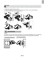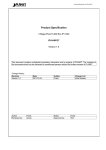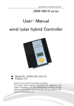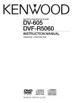
1
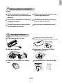
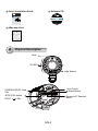
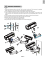
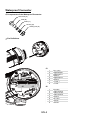
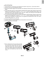
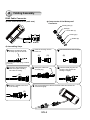
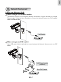
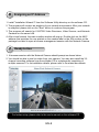
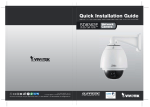
IP8372
Bullet
Network Camera
Quick Installation Guide
6F, No.192, Lien-Cheng Rd., Chung-Ho, New Taipei City, 235, Taiwan, R.O.C.
|T: +886-2-82455282| F: +886-2-82455532| E: [email protected]
繁中
Dansk
Indonesia
簡中
日本語
Français
Español
Deutsch
Português
Italiano
Outdoor • Day & Night • Weather-proof • IP67 •
Cable Management
P/N:625018900G Rev. 1.0
All specifications are subject to change without notice.
Copyright c 2012 VIVOTEK INC. All rights reserved.
VIVOTEK INC.
English
VIVOTEK USA, INC.
2050 Ringwood Avenue, San Jose, CA 95131
|T: 408-773-8686| F: 408-773-8298| E: [email protected]
Türkçe
Polski
Русский
Česky
Svenska
Nederlands
English
Warning Before Installation
Power off the Network Camera as
soon as smoke or unusual odors are
detected.
Refer to your user's manual for the
operating temperature.
Do not place the Network Camera on
unsteady surfaces.
Do not touch the Network Camera
during a lightning storm.
Do not insert sharp or tiny objects
into the Network Camera.
Do not drop the Network Camera.
1
Package Contents
IP8372 with an RJ45 Cable
Sun Shield / Wrench / RJ45 Female /
Female Coupler / Double-sided Tape / Screws
Wall Mount Bracket
Waterproof Connector for RJ45
Ethernet Enclosure
Waterproof Connector (for backup
use)
Alignment Sticker / Desiccant Bag
EN-1
Quick Installation Guide
IP8361
Network Bullet Camera
English
Français
Software CD
Quick Installation Guide
繁中
簡中
日本語
Español
Deutsch
Português
Italiano
Türkçe
Polski
Русский
Česky
Svenska
2MP • Outdoor • Day & Night
Cable Management
5 1 0 0 0 02 2 1 G
Warranty Card
2
Physical Description
Lens
IR LED
Light Sensor
Auto Focus
Reset Button
SD/SDHC/SDXC Card
Slot
NTSC-PAL switch
NTSC
General I/O Terminal
Block
PAL
EN-2
English
3
Hardware Installation
1.Attach the alignment sticker to the wall. Drill four holes into the wall. Then hammer the supplied
plastic anchors into the holes and secure the plate with supplied screws.
2.Fix the intersection bracket to the side of the Network Camera with two screws.
3.Feed the RJ45 cable through the front opening of the wall mount bracket. (If you want to use
external devices such as sensors and alarms, please refer to the assembling steps on the next
page.)
4.Push the spring mortise and hook the bracket onto the groove of the wall mount bracket.
5.Secure the two screws on the other side of the wall mount bracket.
6. Hang the wall mount bracket to the mounting plate.
7.Fix the wall mount bracket with the supplied screw.
8. Adjust the angle of the wall mount bracket to aim at the shooting area.
1
2
3
5
4
6
8
7
EN-3
Waterproof Connector
Components of the Waterproof Connector
Screw Nut (A)
Seal (B)
Seals (C)
Housing (D)
Sealing Nut (E)
Pin Definitions
Fix
n
Alig
J3
8
J6
1
8
1
J3
1
1
2
3
4
5
6
7
8
Do+ (12V)
Digital Output
Digital Input 1
Ground
Digital Input 2
Ground
TV Out +
TV Out -
1
2
3
4
5
6
7
8
Ext. MIC
Audio Ground
Audio Line out
Audio Ground
Ground
DC 12V+
AC24VAC24V+
J6
EN-4
English
Assembling Steps
1. Disassemble the components of the waterproof connector into part (A) ~ (E) as shown above.
2. Open the rear cover of the Network Camera.
3. Remove the rubber stopper from the bottom of the Network Camera and secure the screw nut (A)
tightly.
4. If you need extra power for external devices, please feed the power cable through the wall mount
bracket and the waterproof connector (E --> D --> B --> A) as the illustration shown below. Then
connect the power cord to the socket. Note: There are 7 holes on the seal (B), and the widest hole
with a crack on the side is specific for power cord.
5. If you have external devices such as sensors and alarms, feed the cables through the wall mount
bracket and the waterproof connector (E --> D --> B --> A) as the illustration shown below. Then
refer to the pin definition to connect them to the general I/O terminal block. Note: The recommended cable gauge is 2.0 ~ 2.8 mm.
6. Push the seal (B) into the housing (D).
7. Insert the seals (C) into the empty holes on the seal (B) to avoid moisture.
8. Secure the sealing nut (E) tightly.
5
7
(A)
3
6
(B)
(D)
(C)
(B)
(D)
4
(E)
8
4
(E)
9-1
9-2
9. Open the aluminum foil vacuum bag and take
out the desiccant bag. Attach the desiccant
bag to the inner side of the rear cover, to
under the insulation pad, and then tighten the
rear cover. (Please replace the desiccant bag
with a new one whenever you open the rear
cover.)
EN-5
9-2
4
Cabling Assembly
RJ45 Cable Connector
Components of the Waterproof
Connector
RJ45 Cable Dimension (unit: mm)
Sealing Nut (A)
Seal (B)
Screw Nut (C)
Housing (D)
Gasket (E)
Assembling Steps
1
Prepare an Ethernet cable
and strip part of the sheath.
2
Insert the housing into the
screw nut.
(C)
3
(D)
Insert the seal into the housing.
(B)
Recommended cable gauge: 24AWG
(0.51 mm)
4
Insert the stripped Ethernet
cable through the sealing
nut and the housing.
5
Clamp the cable with
an RJ45 plug.
6
Push the RJ45 plug into the
housing, then secure the
sealing nut tightly.
(A)
7
Attach the gasket to the front
of the housing.
8
Connect the Ethernet cable to the RJ45 cable and secure the
connectors tightly.
(E)
EN-6
English
5
Network Deployment
Power over Ethernet (PoE)
When using a PoE-enabled switch
The Network Camera is PoE-compliant, allowing transmission of power and data via a single
Ethernet cable. Follow the below illustration to connect the Network Camera to a PoE-enabled
switch via Ethernet cable.
PoE Switch
POWER
COLLISION
1
2
3
4
5
LINK
RECEIVE
PARTITION
When using a non-PoE switch
Use a PoE power injector (optional) to connect between the Network Camera and a non-PoE
switch.
PoE Power Injector
(optional)
Non-PoE Switch
POWER
COLLISION
EN-7
1
2
3
4
5
LINK
RECEIVE
PARTITION
6 Assigning an IP Address
1.Install "Installation Wizard 2" from the Software Utility directory on the software CD.
2.The program will conduct an analysis of your network environment. After your network
is analyzed, please click on the "Next" button to continue the program.
3.The program will search for VIVOTEK Video Receivers, Video Servers, and Network
Cameras on the same LAN.
4. After a brief search, the main installer window will pop up. Double-click on the MAC
address that matches the one printed on the camera label or the S/N number on the
package box label to open a browser management session with the Network Camera.
7
Ready to Use
1. A browser session with the Network Camera should prompt as shown below
2.You should be able to see live video from your camera. You may also install the 32channel recording software from the software CD in a deployment consisting of
multiple cameras. For its installation details, please refer to its related documents.
For further setup, please refer to the user's manual on the software CD.
EN-8
English
NOTE:
If you want to use the supplied sun shield for outdoor environments, please follow the steps below to
install:
1. Tighten the supplied two hex couplers.
2. Attach the supplied sun shield to the Network Camera and slide it to the desired position.
3. Fix the sun shield with the supplied two screws.
2
1
3
8
Accessories
VIVOTEK also provides other accessories for versatile applications as the following
illustrations. Please visit VIVOTEK's official website for more purchase information.
Corner Mount Bracket
Pole Mount Bracket
EN-9
IP8372
Bullet
Network Camera
Quick Installation Guide
6F, No.192, Lien-Cheng Rd., Chung-Ho, New Taipei City, 235, Taiwan, R.O.C.
|T: +886-2-82455282| F: +886-2-82455532| E: [email protected]
繁中
Dansk
Indonesia
簡中
日本語
Français
Español
Deutsch
Português
Italiano
Outdoor • Day & Night • Weather-proof • IP67 •
Cable Management
P/N:625018900G Rev. 1.0
All specifications are subject to change without notice.
Copyright c 2012 VIVOTEK INC. All rights reserved.
VIVOTEK INC.
English
VIVOTEK USA, INC.
2050 Ringwood Avenue, San Jose, CA 95131
|T: 408-773-8686| F: 408-773-8298| E: [email protected]
Türkçe
Polski
Русский
Česky
Svenska
Nederlands