1
T
OFFICIAL USE
for ASC & Sales Shop
ECHNICAL INFORMATION
Model No.
Description
PRODUCT
W
EA3200S, EA3201S,
EA3202S, EA3203S
Petrol Chain Saws
P 1/ 15
H
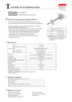
CONCEPT AND MAIN APPLICATIONS
L
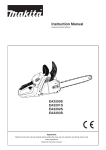
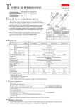
Models EA3200S, EA3201S, EA3202S and EA3203S are entry class
petrol chain saws equipped with 32cc 2-stroke engine, featuring:
• Easy start, On-off choke combination switch and Primer pump
for providing higher maneuverability
• Compact and lightweight body for better handling
• Equipped with catalytic muffler to comply with all known exhaust
emission regulations (for EA3200S and EA3201S only)
(The image above is EA3201S.)
Dimensions: mm (")
EA3200S, EA3201S,
Model
EA3202S EA3203S
Length (L)
405 (16)
Width (W) 250 (9-7/8) 269 (10-5/8)
Height (H)
273 (10-3/4)
These products are available in the following variations.
Saw chain
Catalytic
Guide bar
length: mm
muffler
cutter type
gauge
3/8"
EA3200S30A/ EA3202S30A
Yes/ No
300
90SG-46E
No
3/8"
EA3200S35A/ EA3202S35A
Yes/ No
350
90SG-52E
No
3/8"
EA3200S40B/ EA3202S40B
Yes/ No
400
91VG-56E
No
EA3201S30A/ EA3203S30A
Yes
Yes/ No
300
90SG-46E
3/8"
EA3201S35A/ EA3203S35A
Yes
Yes/ No
350
90SG-52E
3/8"
EA3201S40B/ EA3203S40B
Yes
Yes/ No
400
91VG-56E
3/8"
The models also includes the accessories listed below in "Standard equipment".
Model No.
Tool-less tension
adjustment of
saw chain
Specification
Specifications
Type
Model
Displacement: cm³ (cu.in.)
Engine
Fuel
Max. output: kW (PS)
Max. torque: N.m
Speed at no load: min.-1 = rpm
In compliance with exhaust emission regulations;
EPA Phase 2, EU Stage 2
Fuel tank capacity: mL (US oz)
Chain oil tank capacity: L (US oz)
Carburetor
Ignition type
Starting Easy start (Spring-assisted recoil starter)
system Decompression valve
Primer pump
Clutch
Rotation limiter
Dry weight*: kg (lbs)
EA3200S/ EA3201S
EA3202S/ EA3203S
2-stroke
32 (2.0)
Mixed gasoline
(Mixture ratio of 50:1 [JASO FC or ISO EGD] )
1.35 (1.9) at 10,000 rpm
1.6 at 7,000 rpm
12,800
Yes
(Catalytic converter)
0.4 (13.5)
No
0.28 (9.5)
Diaphragm
Digital CDI
Yes
No
Yes
Yes
Yes
4.1/ 4.2 (9.0/ 9.3)
4.0/ 4.1 (8.8/ 9.0)
* without Guide bar, Saw chain
Standard equipment
Guide bar cover .............. 1
Socket wrench ................ 1
Screwdriver .................... 1
Note: The standard equipment for the tool shown above may vary by country.
Optional
accessories
Saw chains
Guide bars (Sprocket nose type)
Chain oil
Engine oil
P 2/ 15
Repair
CAUTION: Repair the machine in accordance with “Instruction manual” or “Safety instructions”.
[1] NECESSARY REPAIRING TOOLS
Code No.
Description
Use for
1R186
T-type hexalobular wrench
removing/ assembling H.L. (Hexalobular) tapping screw
1R090
1R366
Round bar of copper ø10-180
Feeler gauge set
removing Flywheel
adjusting a proper gap between Flywheel and Ignition coil
1R223
Torque wrench shaft 20-90N.m
1R254
1R220
1R222
134873-0
1R290
1R372
1R396
1R070
1R127
1R181
1R199
Torque wrench shaft 2-6N.m
Ratchet head 9.5
Socket adapter
Bit adapter ass’y
Hexalobular socket head bit
VT-27 (6.35mm)
Crank shaft lock bolt M10
Clutch extractor
Tachometer for engine chain saw
Air density tester
Ignition checker
Spring fixing jig
removing/ assembling Hexalobular tapping screw
using with 1R223/ 1R254 when removing/ assembling Hexalobular
socket head bolt
locking Crank shaft
removing/ assembling Clutch
Checking rpm of engine
Checking the sealing performance of Carburetor and Tank assembly
checking ignition
removing Tension spring 10
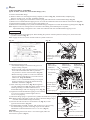
[2] DISASSM|BLY/ ASSEMBLY
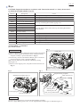
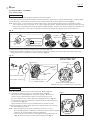
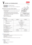
[2]-1. Chain tensioner
Fig. 1
DISASSEMBLING
(1) Remove Sprocket guard, Guide bar and Saw chain from machine.
(2) Remove Guide plate from Guide bar bolts of Engine housing
complete carefully to prevent deformation. (Fig. 1)
(3) If necessary, turn the slotted head of Helical gear 18 clockwise
until 3x10 Tapping screw is appeared. (Fig. 2)
Note: Tension slide can be moved back and forth by turning
Helical gear 18.
(4) Remove 3x10 Tapping screw, and pull out Chain tenstioner set.
(Fig. 3)
Guide plate
Guide bar bolts of
Engine housing complete
Fig. 2
Fig. 3
Slotted head of Helical gear 18
Engine housing complete
Chain tensioner set
Clamp screw
bedding
3x10 Tapping screw
Tension slide
O ring 7
Helical gear 18
Helical gear 11
Gear cover professional
Tension slide
3x10 Tapping screw
ASSEMBLING
Assemble the components by reversing the disassembling procedure.
Be sure to apply Makita grease N No. 2 on the engaged teeth of Helical gear 18 and Helical gear 11.
P 3/ 15
Repair
[2] DISASSEMBLY/ ASSEMBLY
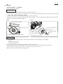
[2]-2. Clutch drum section
DISASSEMBLING
(1) Remove Sprocket guard, Guide bar and Saw chain from machine.
(2) Insert Small-slotted screwdriver into the gap between Crank shaft and Retaining ring E type 6, and then twist Retaining
ring E type 6 using the slotted blade. (Fig. 4)
(3) Remove Flat washer 8 and Retaining ring E type 6 from Crank shaft.
(4) Release chain brake by turn Hand guard toward Tubular handle to remove Clutch drum assemble.if chain brake works.
(5) Remove Clutch drum assembly. (Fig. 5)
Fig. 4
Fig. 5
Small-slotted screwdriver
• Chain-sprocket portion
Retaining ring E type 6
Flat washer 8
• Inside of Clutch
drum assembly
Crank shaft
Flat washer 8
Retaining ring E
type 6
• Needle bearing portion
ASSEMBLING
(1) Check that the following portions of Clutch drum assembly do not have damage/ wear. (Fig. 5)
• Inside
• Chain-sprocket portion
• Needle bearing portion
If there is damage/ wear on Clutch dram assembly, replace it to new one.
(2) Apply a little amount of Makita grease N No. 2 to the needle bearing portion of Clutch drum assembly.
(3) Set Clutch drum assembly, Flat washer 8 and Retaining ring E type 6 in place.
Note: Be sure to use the new Retaining ring E type 6.
P 4/ 15
Repair
[2] DISASSEMBLY/ ASSEMBLY
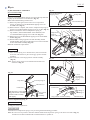
[2]-3. Chain brake section
Note: Wear gloves for safety.
Fig. 6
DISASSEMBLING
(1) Remove Sprocket guard, Guide bar and Saw chain from machine.
(2) Remove Clutch drum assembly. (Figs. 4 and 5)
(3) Turn Hand guard toward Chain bar top side to operate Chain brake.
Note: This allows the tension of Brake guard to be relaxed.
(4) Remove two 3x10 Tapping screws and Brake cover from Engine
housing complete. (Fig. 6)
(5) Lift the round portion of Brake band in the direction of the arrow.
(Fig. 7) And then, remove the hooked end portion of Brake band.
Brake band is removed from brake mechanism.
(6) Hold Machine so as not to be moved.
(7) Pull and remove Tension spring 10 with 1R199 in the direction of
the arrow drawn in Fig. 8.
Fig. 7
Brake cover
3x10 Tapping
screw (2 pcs.)
Engine housing complete
Hand guard
4.7x16 Hexalobular
tapping screw
Pin B of Engine
housing complete
Compression
spring 6
4mm
Pin A of Engine
housing complete
Flat washer 5
[viewed from Chain bar installation side]
Pin A of Engine
housing complete
Spacer sheet
metal
Pin B of Engine
housing complete
Tension spring 10
Stop ring E-4
Link plate complete
Bush 6 (2 pcs.)
Spacer sheet metal
Stop ring E-4
Engine housing complete
Round portion of Brake band
Bush Link plate complete
Hand guard guide
Hooked end portion
of Brake band
Bush
Brake band
Fig. 8
(8) Remove Starter complete. Refer to [2]-7 “Recoil starter section”.
(9) Remove 4.7x16 Hexalobular tapping screw and Flat washer 5 from
Tension spring 10
1R199
Starter complete installation side on Hand guard. (Fig. 7)
(10) Remove Stop ring E-4 from Pin A of Engine housing complete. (Fig. 7)
(11) Lift up the Pin A side of Spacer sheet metal, and then lower it a little
to remove the Pin B side of Spacer sheet metal from Pin B.
Remove Spacer sheet metal from Engine housing complete completely.
(12) Remove Bush 6 from Pin A/ B (one each). (Fig. 7)
(13) Cover Engine housing complete with cloths, and hold them in Vise.
(14) Remove Link plate complete from Engine housing complete
in the horizontal direction of Pin A/ B. (Fig. 7)
(15) Remove Muffler section. Refer to [2]-4 “Muffler section”.
(16) Remove the recoil starter side end of Hand guard in the direction of Muffler installation side, then move the chain bar
side end of Hand guard back and forth lightly to remove from Pin B of Engine housing complete.
ASSEMBLING
Assemble the components by reversing the disassembling procedure.
Note: • Be sure to apply Makita grease N No. 2 on the engaged teeth of Helical gear 18 and Helical gear 11.
• Make sure that Hand guard guide is not unhooked. Push it back into position that is 4mm distance from Pin B
using Screwdriver so that Hand guard guide and Hand guard can be set in place.
• Be sure to use the new Stop ring E-4.
P 5/ 15
Repair
[2] DISASSEMBLY/ ASSEMBLY
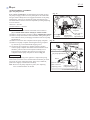
[2]-4. Muffler section
Note: • Wear gloves for safety.
• Be careful that Muffler stays very hot for a while after running the engine.
DISASSEMBLING
(1) Remove Sprocket guard, Guide bar and Saw chain from machine.
(2) Unscrew M5x40 Hexalobular socket head bolt and two M5x16 Hexalobular socket head bolts as drawn in Fig. 9,
and then disassemble Muffler section as drawn in Fig. 10.
Fig. 9
*Muffler (Inner)
*Muffler (Center)
*The components of
Muffler complete
(Refer to Fig. 10.)
*Muffler (Outer)
M5x40 Hexalobular
socket head bolt
*Spark arrester screen
M5x16 Hexalobular
socket head bolt (2 pcs.)
Fig. 10
Muffler complete
M5x16 Hexalobular
socket head bolt (2 pcs.)
Cooling plate
Connecting link
Gasket
Muffler section
ASSEMBLING
Assemble the components of Muffler section by reversing the disassembling procedure.
Be careful to each direction.
P 6/ 15
Repair
[2] DISASSEMBLY/ ASSEMBLY
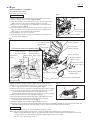
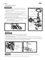
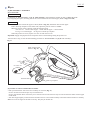
[2]-5. Clutch section
DISASSEMBLING
(1) Remove Sprocket guard, Guide bar and Saw chain from machine.
(2) Pull Hand guard toward Tubular handle to release Chain brake. Then, remove “Clutch drum assembly”. Refer to [2]-2.
(3) Set 1R396 on Clutch and turn it clockwise using Cordless impact driver with 19mm Socket bit. (Fig. 11)
Note: In most cases, it can be loosen by Cordless impact driver without removing Spark plug as Crank shaft is locked
with compression force in Cylinder. If not, remove Spark plug and set 1R372 in the hole for Spark plug after moving
Piston to the lower dead point (visible through the exhaust opening). And then, turn 1R396 by hand tool because use of
Cordless impact driver may cause Crank shaft lock bolt to hit and possibly damage the top surface of Piston.
Fig. 11
1R396
Cordless
impact driver
ø35mm
ø3-25mm
19mm width
across flats
Socket bit
19mm width
across flats
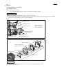
(4) Remove Flat washer 10 (large) and Flat washer 10 (small). (Fig. 12)
(5) Push out Clutch driver carefully so as not to pinch your finger. It is tightly fit in between two Clutch shoes with strong
spring reaction force worked by two Tension springs 5. (Fig. 12)
Fig. 12
[Clutch complete viewed
from Flat washer side]
Clutch driver
Clutch driver
Clutch
shoe
(2 pcs.)
Crank shaft
Marks
Flat washer 10 (small)
Flat washer 10 (large)
Tension spring 5 (2 pcs.)
Clutch complete
Push this area of Clutch driver.
Note: Do not push out Clutch driver to your side.
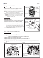
ASSEMBLING
Note: Be careful to each direction of the components. Refer to Fig. 12.
Fig. 13
(1) Assemble two Tension springs 5 to two Clutch shoes. (Fig. 13)
Be careful to the hooking direction of Tension springs 5. When one of
Tension spring 5 has a damage, replace two Tension springs 5 with
the new at the same time. Do not replace the damaged one only. (Fig. 13)
Fit one of Clutch shoe to Clutch driver, and then hook the other Clutch shoe
to Clutch driver. (Fig. 13)
Push Clutch driver until it stops to assemble Clutch complete securely.
(2) Set Flat washers 10 (large, small) and Clutch complete in place by reversing
the disassembling procedure.
Note: • The fastening torque of Clutch complete has to be 35 ± 2.5 N·m.
When Clutch complete is fastened to Crank shaft, remove Starter complete
in advance to prevent Ratchets from being damaged.
• Face the marks on Clutch driver to the opposite of Large flat washer 10.
(Fig. 12) Face the marks to Clutch drum assembly side. (Fig. 5)
P 7/ 15
Repair
[2] DISASSEMBLY/ ASSEMBLY
[2]-6. Oil pump section
Refer to Figs. 14 and 15 for the mechanism of Oil pump section.
Oil pump to supply Chain oil runs by Pump drive on Crank shaft.
The gear teeth of Pump drive are engaged with those of Oil pump,
and therefore, Chain oil is supplied to Chain when Engine runs.
The fluid amount of Chain oil can be adjusted by turning Adjusting
screw as follows:
clockwise = increase
counterclockwise = decrease
Fig. 14
Pump drive
DISASSEMBLING
Oil pressure line
complete
(1) Remove Clutch drum section and Clutch section. Refer to
[2]-2 “Clutch drum section” and [2]-5 “Clutch section”.
Gear teeth of
4.7x16
(2) Remove Tension spring 10. Refer to [2]-3 “Chain brake section”.
Adjusting screw Hexalobular
Oil pump
(3) Remove Pump drive from Crank shaft while sliding Pump drive
for oil fluid
tapping screw adjustment set
back and forth slowly to disengage with Gear teeth of Oil pump
adjustment set.
(4) Remove Oil suction line complete from Oil pump complete. Fig. 15
(5) Remove Oil pump complete from Engine housing complete
Pump drive Oil suction line complete
by unscrewing 4.7x16 Hexalobular tapping screw.
(6) Oil suction line complete is in Engine housing complete
with Oil pump complete and Chain oil tank connected. And
Oil pressure
Oil pump complete
therefore, pull Oil suction line complete carefully out of
line complete
Engine housing complete, then remove Oil suction line
Body
complete from Oil pump complete as drawn in Fig. 15.
Oil pump adjustment set
ASSEMBLING
While pushing Adjusting screw against its compression spring
reaction force, turn the screw counterclockwise until the pin ends
are fit into two slits of Oil pump body. If this way is difficult,
push Piston slightly in the direction of Body.
Note: When set Oil pump complete in place, turn Adjusting
screw counterclockwise to the full.
Piston
Pin ends
Slits
Pass Pin ends through
Slits to remove
Adjusting screw with
Adjusting screw. compression spring
4.7x16 Hexalobular tapping screw
P 8/ 15
Repair
[2] DISASSEMBLY/ ASSEMBLY
[2]-7. Recoil starter section
Fig. 17 (The components of Starter complete)
DISASSEMBLING
Refer to Figs. 16 and 17 for the mechanism of Recoil starter section.
Air guide plate
(1) Remove three 5.5x16 Hexalobular tapping screws and Housing of
Starter complete. (Fig. 16)
(2) Remove Air guide plate. and then loosen the force of Rewind spring
5x12 Tapping screw
as follows:
After making the slack of rope between Starter grip and Reel,
Cam plate
put the slack into the groove of Reel and pull the starter grip lightly.
Note: Be sure to loosen the spring force before the step (3).
Torsion spring 20
(3) Remove 5x12 Tapping screw, and then separate Cam plate and Torsion
Rewind spring set Reel
spring 20 from the center pin of Housing.
(factory-assembled)
(4) Remove Reel from the center pin of Housing.
(5) Remove Rewind spring set from Housing by rotating Housing carefully.
Note: Rewind spring may pop out of Housing, and therefore, wear goggles
Spring
for eye protection and gloves.
cassette
If Rewind spring popped out, reset it in Spring cassette.
Rewind
Refer to “Rewind spring set” in Fig. 17.
spring
Fig. 16
(Housing of Starter
Housing of
complete)
Starter complete
Center pin of
Housing
Square washer 4
Starter rope
5.5x16 Hexalobular tapping screw (4 pcs.)
Starter grip
[2]-8. Flywheel
DISASSEMBLING
(1) Remove Sprocket guard, Guide bar and Saw chain from the machine.
(2) Remove “Recoil starter section”. See [2]-7 “Recoil starter section”.
(3) Remove Spark plug and set 1R372 into the hole for Spark plug to prevent Crank shaft from being turned together with
M8x1 Hex nut in the next step.
(4) Remove M8x1 Hex nut by turning it counterclockwise with Socket wrench, and then remove Spring washer 8. (Fig. 18)
(5) While holding the machine by hand or securing it on workbench with soft cloths seated on, tap Crank shaft end with 1R090.
Flywheel is removed from the taper portion of Crank shaft by the shock. (Fig. 19)
Fig. 18
Fig. 19
M8x1 Hex nut
Spring washer 8
(between M8x1
Hex nut and
Flywheel complete)
Socket wrench
Flywheel
complete
1R090
Hold the machine.
ASSEMBLING
Set Flywheel to the taper of Crank shaft, and place Spring washer 8. Then, tighten M8x1 Hex nut to fastening torque
20 ± 5 N·m.
Note: The taper portion of Crankshaft must always be degreased before assembly.
P 9/ 15
Repair
[2] DISASSEMBLY/ ASSEMBLY
[2]-9. Ignition coil
Fig. 20
Flag terminal
of cable harness
DISASSEMBLING
(1) Remove Sprocket guard, Guide bar and Saw chain from
the machine.
(2) Remove “Recoil starter section”. See [2]-7.
(3) Remove Flag terminal on one of cable end from Ignition coil.
Note: The other cable end cannot be removed from Ignition coil
because they are integrated as a Cable harness.
(4) Remove two M5x20 Hexalobular socket head bolts. (Fig. 20)
Ignition coil with Cable harness is removed from Flywheel.
(Fig. 21)
Note: Do not lose two Isolating washers between Cylinder
and Ignition coil. (Fig. 21)
M5x20
Hexalobular
socket head
bolt (2 pcs.)
Ignition coil
0.25 to 0.3mm
Flywheel
Fig. 21
ASSEMBLING
Refer to Figs. 20 and 21.
(1) Insert two Isolating washers into two seated holes of Cylinder.
(2) Pretighten Ignition coil in place by tightening two M5x20
Hexalobular socket head bolts through Isolating washers.
(3) Insert 1R366 between Ignition coil and Flywheel and adjust
the clearance of 0.25 to 0.3mm as follows:
• Once unscrewing two M5x20 Hexalobular socket head bolts,
Push Ignition coil toward Flywheel carefully and check the
clearance. If the above clearance is obtained, tighten the bolts
to fastening torque 5 ± 0.5 N·m.
(4) Connect Flag terminal of Cable harness to Ignition coil.
Flag terminal of Cable harness
for connecting with Ignition
M5x20
Hexalobular
socket head
bolt (2 pcs.)
Ignition coil
Cable harness
Isolating washer (2 pcs.)
Cylinder
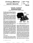
[2]-10. Air filter, Carburetor, Intermediate flange
DISASSEMBLING
Note: Drain Fuel tank before disassembling Carburetor.
See Fig. 22. (1) Remove Hood.
(2) Turn Choke lever to the position of “STOP”.
(3) Remove two M4x40 Hexalobular socket head bolt on Intake manifold.
(4) Remove Air filter cover, Air filter, and Intake manifold.
(5) Remove one end of Tube 3-70 and one end of Tube 2.5-72 from Carburetor. (Fig. 23)
Note: Gasoline is left in Tube 3-70, and therefore, clean the gasoline with a cloth.
(6) Remove Carburetor from Throttle linkage.
Note: When setting Carburetor in place, hook Throttle linkage to the hole of Lever-throttle (designated by Black arrow in
Fig. 22).
Fig. 22
Fig. 23
Tube 3-70
removed from
Carburetor
5.5x16 Hexalobular
tapping screw (2 pcs.)
Air filter
cover
Tube 2.5-72 removed from
Carburetor
Intermediate
flange
Air filter
Intake
manifold
Stop
mark
Choke
lever
Cable harness
3x10 Tapping
screw
Contact spring
5.5x16 Hexalobular
tapping screw (2 pcs.)
P 10/ 15
Repair
[2] DISASSEMBLY/ ASSEMBLY
[2]-10. Air filter, Carburetor, Intermediate flange (cont.)
To remove Intermediate flange:
(1) Remove Choke lever from Engine housing complete (as drawn in Fig. 25), Tubular handle, and Spark plug.
Remove Air filter cover, Air filter, and Intake manifold.
(2) Remove 3x10 Tapping screw that fastens Contact spring and Cable harness to Intermediate flange. (Fig. 23)
(3) Remove four 5x40 Hexalobular tapping screws on Crank case underside located on the bottom of the machine. (Fig. 24)
(4) Turn Flywheel carefully so as not to touch it with Ignition coil.
(5) Remove the assembled part of Cylinder, Intermediate flange, and Ignition coil from the machine by pulling them. (Fig. 25)
Note: Replace Crank case sealing with new one before reassembling the assembled part of Cylinder,
Intermediate flange, and Ignition coil to Crank case underside with four 5x40 Hexalobular tapping screws.
ASSEMBLING
(1) Move Piston to the upper dead point. While holding the position of Piston parallel to Piston pin 8, insert Piston into
Cylinder as drawn in Fig. 25.
Note: Supply 2stroke oil to Piston and the inside of Cylinder in advance.
Fig. 24
Fig. 25
Crank case underside
5x40
Hexalobular
tapping screw
(4 pcs.)
Piston
Choke lever removed
from Engine housing
complete
Fig. 26
(2) Check the following points.
Tube 2.5-72
Guide pin of
Tube 3-70
• Intermediate flange is inserted into the groove on
removed from
Engine housing
removed from
Engine housing complete.
Carburetor
Carburetor
complete
• When Cylinder comes into Engine housing complete, 3x10 Tapping screw
Pulse tube end and Red tube end are placed on
the position to connect with Carburetor. (Fig. 26)
Intermediate
flange
• Before fastening Cylinder to Crank case underside,
the wire end of Cable harness is put in the notch of
Choke lever. (Figs. 26 and 25)
• Tube 2.5-112 is routed behind Guide pin of Engine
housing complete to prevent the Tube from being
Grounding wire
attached to Carburetor. (Fig. 26)
of Cable harness
(3) After connecting Choke lever (Fig. 25) and Ignition
coil with Cable harness (Fig. 21), fasten Contact spring Notch of Choke
and the grounding wire end of Cable harness to
lever
5.5x16 Hexalobular
Tube 2.5-112
Intermediate flange with 3x10 Tapping screw. (Fig. 26)
Contact
spring
tapping
screw
(2
pcs.)
to Fuel nipple
(4) Tighten four 5x40 Hexalobular tapping screws manually
in a criss-cross pattern, and then tighten them to
Fig. 27
10 ± 0.5 N·m properly.
Carburetor
(5) Check that Ring spring 8 is put between Cylinder and Intake hose properly.
Tube 2.5-112
Note: Before setting Carburetor in place, be sure to check that Flange ring is
mounted on Intermediate flange horizontally.
(To Cylinder)
(6) Connect the ends of Tube 2.5-72 and Tube 3-70 (Fig. 27) to each
Tube 2.5-55
pipe-end of Carburetor. (Fig. 26)
Tube 2.5-72
(7) Assemble Intake manifold, Air filter, and Air filter cover by reversing
Tube 3-70
the disassembling procedure. Fastening torque for each M4x40
Primer
pump
Hexalobular socket head bolt has to be 3 ± 0.5 N·m. (Fig. 23)
O ring 11.5
Important:
Fuel nipple
Fuel line (in Fuel tank)
When assembling Fuel suction Tube 3-70 to Fuel nipple, make sure
the insertion is perfect. (Fig .27)
(connected to Gasoline filter)
P 11/ 15
Repair
[2] DISASSEMBLY/ ASSEMBLY
[2]-10. Air filter, Carburetor, Intermediate flange (cont.)
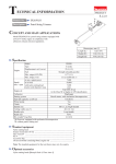
Fig. 28
Needle adjustment
(S)
L
See Figs. 28 and 29 for the positions of Needle-idle (L) and Needle-high speed (H).
Carburetor has two different specifications (Walbro-made and ZAMA-made).
After tightening each Needle to the full, loosen them as listed below.
Walbro
L-needle 1-1/2
H-needle 4-1/4
H
ZAMA
1-1/4
2
Note: Adjust the rpm from the above setting positions with 1R070.
Pressure test
Fig. 29
(1) Connect 1R127 to Carburetor. (Fig. 29)
(2) Push up the air pressure until the pressure gauge indicates
Carburetor
0.05 Mpa.
Connect 1R127
(3) The carburetor is in order if the air pressure can be kept for
to the fuel nipple.
10 seconds.
Note: If the air pressure drops, check the following conditions.
• Valve-inlet needle: if necessary, Spring, Lever-metering,
Pin-metering lever, and Plug-welch have to be replaced
together. (Fig. 30)
• Dirt/ deposits on the top of Valve-inlet needle: clean it.
• Gasket pump and Diaphragm-pump: replace them
Fig. 30
with the new ones.
Screw-idle adjustment (S)
General check
1R127
• Inlet screen should be clean.
• Pulse hole should be clean.
Pulse hole
Check around Valve-inlet needle and Lever-metering
Gasket pump
Refer to Figs. 30 and 31.
Check that the tip of Valve-inlet needle is not worn.
Replace it the new one if it looks worn.
Check that Lever-metering is not worn and it is assembled
properly as drawn in Fig. 31.
Note: Low position of Control lever causes;
• Insufficient fuel circulation
• No maximum power
High position of Control lever causes;
• Carburetor flooding
• Starting problems
• Poor idling
• Poor acceleration
If necessary, reassemble them properly / replace them with
the new ones.
Diaphragm-pump
Needle-idle
L
Inlet screen
Needle-high speed
H
Spring
Lever-metering
Pin-metering lever
Plug-welch
Gasket-metering
diaphragm
Diaphragm
assembly-metering
Check Diaphragm-pump
• When Diaphragm-pump is dented, torn, or creased,
• When the valve flaps of Diaphragm-pump are bent,
replace Diaphragm-pump and Gasket-pump with new ones.
Push
Valve-inlet needle
Fig. 31
(Position of Lever-metering)
Check Diaphragm assembly-metering
• (i) When Diaphragm assembly-metering is dented, hardened,
or torn,
(ii) If there is a visible wear on the button of Diaphragm
assembly-metering
• If Diaphragm assembly-metering lacks elasticity, replace
Diaphragm assembly-metering and Gasket-metering diaphragm
with new ones.
Correct
Too high
Too low
P 12/ 15
Repair
[2] DISASSEMBLY/ ASSEMBLY
[2]-11. Tank assembly
Fig. 32
5.5x16 Hexalobular
tapping screw
DISASSEMBLY
Catch lever
Unscrew 5.5x16 Hexalobular tapping screw and pull Grip shell half
slightly up and toward the screw hole side. (Fig. 32)
Note: When disassembling Throttle lever:
(1) Remove Sprocket guard, then remove two Compression
springs 12 and four 5.5x16 Hexalobular tapping screws on
A and B sides. (Fig. 33)
Fig. 33
(2) Remove Starter complete, then remove Compression spring 12
and two 5.5x16 Hexalobular tapping screws on C side. (Fig. 33) Tubular handle Cup washer 6
(3) Remove Hood, then remove Compression spring 12,
Cup washer 6, M5x16 Hexalobular socket head bolt, and
Compression
spring 12
5.5x16 Hexalobular tapping screw on D side. (Fig. 33)
(4 pcs/ A,B,C,D)
(4) Remove four 5.5x16 Hexalobular tapping screws and Tubular
handle. (Fig. 34)
C
(5) Pull the sides of the grip portion of Tank assembly toward
outside slightly and swing up Throttle lever to remove Throttle
section from Tank assembly. (Fig. 35)
Note: Be careful not to pull Tubes.
Grip shell
Throttle lever
M5x16 Hexalobular
socket head bolt
D
A
ASSEMBLY
(1) Place Torsion spring 10 on Throttle lever, then turn Throttle
lever 180° and set them in place on the grip portion of Tank
assembly.
(2) Set Catch lever to the hinge position of Tank assembly.
(Fig. 35)
Note: Torsion spring 10 has to be hooked with Throttle lever
as drawn in Fig. 36.
B
5.5x16 Hexalobular
tapping screw (7 pcs.)
Fig. 34
Tubular handle
Fig. 35
Grip shell
Torsion spring 10
Throttle lever
Catch lever
Pull the hinges 1 and 2
(Fig. 36) of Tank assembly
toward outside carefully
and slightly.
5.5x16
Hexalobular
tapping screw
(4 pcs.)
Grip portion
of Tank
assembly
Fig. 36
Torsion spring 10
Catch lever
Hinge 1
Hinge 2
Grip portion of Tank assembly
Throttle lever
[2]-12. Compression spring 12
DISASSEMBLING
See Fig. 33 and the explanation.
ASSEMBLING
Assemble four Compression springs 12 by reversing the disassembling procedure.
Note: Be sure to set Cup washer 6 between Tubular handle and Compression spring 12 as drawn in D side in Fig. 33,
and then screw M5x16 Hexalobular socket head bolt to Cylinder 38.
P 13/ 15
Repair
[2] DISASSEMBLY/ ASSEMBLY
[2]-13. Fuel tank
DISASSEMBLY
(1) Referring to “DISASSEMBLY of [2]-11. Tank assembly”, disassemble the machine as drawn in Figs. 34 and 33.
(2) Using long-nose pliers, carefully pull out the one end of Fuel line from Fuel nipple. (Refer to Figs 37 and 28)
ASSEMBLY
Note: Connect the one end of Fuel nipple to 1R127 (Refer to Fig. 29), and fill the other of Fuel nipple.
Fasten Tank cap complete to Fuel Tank. Then, adjust the pressure value to 0.03MPa.
When the pressure value is descent, check the following parts:
• Air valve set • Ends of Fuel nipple • Intake of Fuel nipple • Gasoline filter
• O ring 11.5 on Fuel nipple • O ring 29.5 of Tank cap complete
When the pressure is ascent, replace Air valve set with the new one.
Important: Supply Soap liquid onto the suspicious surface of Fuel leakage during the pressure test.
After the above steps, reverse the disassembling procedure of “DISASSEMBLY of [2]-11 Tank assembly”.
Fig. 37
Fuel nipple
Ends of Fuel nipple
(Refer to Fig. 27)
Air valve set
Gasoline filter
Tank cap complete
[2]-14. How to remove Gasoline filter/ Fuel line
• Pick up Gasoline filter with a bent wire carefully out of Tank. (Fig. 37)
Do not use Pliers because the tips may scratch Fuel line.
Do not pull Gasoline filter/ Fuel line by force without care because Fuel line may be removed from the intake of Fuel nipple
inside Tank.
• Turn Fuel nipple slightly counterclockwise and then remove it from Tank assembly with small-slotted screwdriver carefully.
Note: Do not lever Nipple at the ends on the top. They may be broken off.
P 14/ 15
Repair
[2] DISASSEMBLY/ ASSEMBLY
[2]-15. Cylinder, Piston
DISASSEMBLY
(1) Remove “Air filter, Carburetor, and Intermediate flange” as mentioned in [2]-10. (Figs. 22, 23, 24, and 25)
(2) Piston set can be separated from Crank shaft by removing Ring spring 8 from Piston with Long-nose pliers. (Fig. 38)
ASSEMBLY
Note: Supply 2-stroke engine oil to Piston and the inside of Cylinder in advance.
Important: See Figs. 38 and 39.
• Set Piston in place with the arrow marking faced to Muffler side.
• Face the gap of Piston ring 38 to Carburetor side. Make sure that a small projection in Piston groove comes
in the gap of Piston ring 38.
• Ring spring 8 and Piston pin 8 have to be installed into Piston through Needle cage 810 and Crank shaft from
Guide bar side.
• Be sure to use New Gasket (Fig. 10) and New Crank case sealing.
• When replacing Ball bearing 6201, press-fit the inner ring portion to Crank shaft using the same size pipe
and a block for placing the counterweights without bending.
After the above steps, reverse the disassembling procedure of “DISASSEMBLING of [2]-11. Tank assembly.
Fig. 38
Fig. 39
Piston ring 38
Small projection
in the groove of
Piston
[Carburetor side]
Cylinder
piston set
Arrow marking
on Piston
Piston pin 8
[Carburetor side]
[Guide bar side]
Piston set
[Guide bar side]
Piston ring 38
Piston pin 8
Ring spring 8
Ring spring 8
Crank shaft set
Crank shaft
Needle cage 810
Counterweights
Ball bearing 6201
Needle cage 810
Crank case sealing
Crank case underside
Bush 6 (4 pcs.)
5x40 Hexalobular
tapping screw (4 pcs.)
(See Fig. 24.)
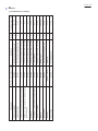
M5x16 Hexalobular socket head bolt
M5x40 Hexalobular socket head bolt
266605-8
266606-6
266631-7
264053-5
266651-1
Ignition coil assembly
Flywheel
Tubular handle
Contact spring
266421-8
168599-2/ 168401-9
168607-9
Clutch (M10 -1.0 thread pitch/ Left hand thread)
Spark plug
266604-0
Carburetor
Muffler cover (the component of Muffler complete)
and Cooling plate
M5x16 Hexalobular socket head bolt
266605-8
Muffler base (the component of Muffler complete)
3x10 Tapping screw
Spark plug
5.5x16 Hexalobular tapping screw
M8x1 Hex nut
M5x20 Hexalobular socket head bolt
Clutch complete
M4x40 Hexalobular socket head bolt
5.5x16 Hexalobular tapping screw
266651-1
Intermediate flange
5x40 Hexalobular tapping screw
Description
266608-2
Part No. of Screw/ Bolt/ Clutch
Crank case underside
Fastening for
1
1
4
1
2
1
2
1
2
2
2
4
Quantity
1 ± 0.2
11 ± 2
4 ± 0.5
22.5 ± 2.5
5 ± 0.5
35 ± 2.5
3 ± 0.5
8±1
8±1
8±1
4 ± 0.5
10 ± 0.5
Fastening torque (N.m.)
Repair
P 15/ 15
[3] TIGHTENING TORQUE