1
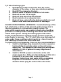
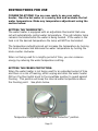
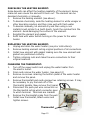
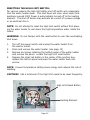
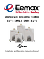
Electric Mini Tank Water Heaters EMT1 - EMT2.5 - EMT4 - EMT6 Installation and Operating Instruction Manual Table of Contents Important Safety Instructions Technical Data 2 3-4 General Information 5 Technical Description 6 Installation Instructions 6-10 Plumbing Connections 7 Temperature & Pressure Relief Valve Filling The Water Heater 7-8 9 Electrical Connections 10 Instructions For Use 11 Maintenance Instructions 12-14 Trouble Shooting 15 Schematic Disassembly & Parts List 16 Warranty 17-18 Page 1 IMPORTANT SAFETY INSTRUCTIONS WARNING: When using electrical appliances, safety precautions to reduce the risk of fire, electric shock or injury to persons should be followed, including: 1. READ ALL INSTRUCTIONS BEFORE USING THIS WATER HEATER. 2. This water heater must be grounded. Connect only to properly grounded outlet. See “GROUNDING INSTRUCTIONS” found on page 10. 3. Install or locate this water heater only in accordance with the provided installation instructions. 4. Use this water heater only for its intended use as described in this manual. 5. Do not use an extension cord set with this water heater. If no receptacle is available adjacent to the water heater, contact a qualified electrician to have one properly installed. 6. As with any appliance, close supervision is necessary when used by children. 7. Do not operate this water heater if it has a damaged cord or plug, if it is not working properly, or if it has been damaged or dropped. 8. This water heater should be serviced only by qualified service personnel. Contact nearest authorized service facility for examination, repair, or adjustment. SAVE THESE INSTRUCTIONS The manufacturer and/or distributor is not responsible for damages caused by improper installation, or by non observance of the instructions in this manual. A QUALIFIED, LICENSED TECHNICIAN MUST ALWAYS INSTALL THE WATER HEATER AND CONDUCT ALL SUBSEQUENT SERVICE WORK AND/OR MAINTENANCE. IMPORTANT!!! NEVER TURN THE WATER HEATER POWER ON UNTIL THE TANK IS COMPLETELY FULL AND WATER IS FLOWING OUT OF THE HOT WATER FAUCET. Page 2 Technical Data MODEL EMT1 EMT2.5 EMT4 EMT6 Capacity gallons 1.3 2.5 4.0 6.0 Voltage Vac 110-120 110-120 110-120 110-120 Watts 1440 1440 1440 1440 Max. Water Pressure psi 150 150 150 150 Weight (empty) lbs. 12.5 20 24 26 Amps 12 12 12 12 1 1 1 1 Power at 120 Vac Amperage Phases Temperature and Pressure Relief Valve Water outlet Water inlet Assembly Figure water inlet water outlet Water Flow Figure Page 3 & Dimensions Model EMT1 EMT2.5 EMT4 EMT6 A (inch) 12 1/2” 14 1/2” 19 1/4” 18” B (inch) 11” 11 3/4” 11 3/4” 15 3/4” C (inch) 10” 10 3/8” 10 3/8” 15 1/2” $ % Schematic Construction Heating element Switch Wiring Diagram Thermostat Indicate Light Heating Element Power Plug 1 / Overheat Limiter Switch Switch ( 1 / Wire Support Page 4 GENERAL INFORMATION The Eemax Mini Tank water heaters can be used in most under the counter, point of use applications. EMT models are designed to supply hot water for all hand wash and kitchen sinks in a residential, commercial or industrial environment. EMT models can replace traditional central hot water heaters thereby conserving water and reducing energy waste. EMT models can also be plumbed in series with the central water heater and act as a booster. The Eemax Mini tank water heaters are lightweight and compact and manufactured for easy installation. EMT models are designed to be mounted on the wall. EMT models are designed to operate at 150 psi maximum water pressure. Install a pressure reducing valve if your water pressure is greater than 150 psi. CAUTION!: The manufacturer cannot be responsible for the damage caused by improper installation or by failure to follow instructions in this manual. Comply with the Installation Instructions before connecting to electrical outlet. CAUTION!: The thermostat has been pre-set at the factory between 41C (105F) and 45C (113F). CAUTION!: Hydrogen gas can be produced in a hot water system served by this heater that has not been used for a long period of time (generally 2 weeks or more). Hydrogen gas is extremely flammable. To reduce the risk of injury under these conditions, it is recommended that the hot water faucet be opened for several minutes at the nearest and most distant sink being served by this water heater before using any electrical appliance connected to the hot water system i.e. Dishwasher. If hydrogen gas is present, there will probably be an unusual sound such as air escaping through the faucet as the water begins to flow. There should be no smoking or open flame near the faucet at this time. WARNING: Installer should review the contents of this manual with the owner upon completion of the installation, and the manual should remain with the owner and placed in a location close to the water heater. Page 5 TECHNICAL DESCRIPTION There are four Eemax Mini tank models, a 1.3 gallon, a 2.5 gallon, a 4 gallon and a 6 gallon model. The pressure vessel (water tank) is welded, glass lined steel and is equipped with an anode rod. The water heater is equipped with a thermostat and a high limit temperature switch. A temperature/pressure relief valve is supplied with the unit. INSTALLATION INSTRUCTIONS EMT1 - EMT2.5 - EMT4 - EMT6 The installation must be completed by a licensed professional. All state and local codes must be adhered to. The manufacturer will not be liable for any damages because of failure to comply with these installation instructions or because of improper installation performed by an unqualified installer. CHOOSE A LOCATION that allows ease of access for maintenance or servicing, ideally installed at least 8” to 9” from the ceiling (inside top of cabinet) or any adjacent walls. WALL MOUNTING Fasten the supplied mounting bracket to the wall. Use screws that are suitable for the wall material and the weight of the water heater filled to capacity (EMT1 = 24 lbs. - EMT2.5 = 41 lbs. - EMT4 = 57 lbs. - EMT6 = 76 lbs.). Hang the water heater on the bracket and pull downwards on the water heater to insure that both “fingers” of the bracket are seated in the mounting slots. Confirm your water piping orientation (hot and cold) before wall mounting. ONLY INSTALL IN VERTICAL POSITION. Heater can sit on the floor. Confirm water piping orientation before finalizing on floor. ONLY INSTALL IN VERTICAL POSITION! EMT models can be installed under the sink. Page 6 PLUMBING CONNECTIONS Connect the cold water inlet pipe to the inlet nipple (marked with a blue ring) and the hot water outlet pipe to the outlet nipple (marked with a red ring). IMPORTANT: If Water pipes are copper or bronze, use dielectric connections to prevent corrosion. Failure to provide dielectric insulation may result in premature tank or nipple failure and may void your warranty. Insure that the water heater is installed in a level position. Install a shut off valve on the cold water side of the water heater. The valve is for servicing and the valve should be in the open position when the water heater is in operation. In order to protect the water heater from heat damage due to soldering, solder a piece of tubing to a threaded UNION fitting before screwing the UNION to the tank. DO NOT APPLY HEAT DIRECTLY TO INLET OR OUTLET CONNECTIONS. TEMPERATURE AND PRESSURE RELIEF VALVE: CAUTION!: Install the Temperature/Pressure Relief Valve supplied with the water heater! Install a discharge pipe from the temperature/pressure relief valve terminating at a sink or drain. DO NOT CAP OR PLUG THE END OF THE DISCHARGE PIPE. THE DISCHARGE PIPE MUST BE UNOBSTRUCTED AND FULL SIZED. The T/P valve is certified by a nationally recognized test lab that maintains periodic inspections of the listed equipment and meets the requirements for relief valves and automatic shut off devices for hot water supply systems ANSI 121.22-1979. The T/P valve is marked with a maximum pressure, which does not exceed the maximum working pressure of the water heater (150 PSI). Install the T/P valve into the threaded opening at the top of the water heater and orient the discharge tubing so that any discharge from the valve will exit within 6 inches above, or at any distance below the structural floor, and cannot contact any live electrical part. Page 7 T/P Valve Discharge pipe: 1. Must NOT be smaller in diameter than the outlet diameter of the valve, or have any reducing couplings. 2. Must NOT be plugged or blocked. 3. Must be made of suitable material for hot water. 4. Must not be over 15’ in length. 5. Must not have more than two elbows. 6. Must terminate at an adequate drain. 7. Must not have a shut off valve between relief valve and tank or relief valve and termination of discharge. CLOSED SYSTEM THERMAL EXPANSION: Periodic discharge of the T/P relief valve or failure of the element gasket may be due to thermal expansion in a closed water supply system. The water utility supply meter may contain a check valve, backflow preventer or water pressure reducing valve which will create a closed water system. During the heating cycle of the water heater, the heated water expands causing pressure inside the water heater to increase. The T/P relief valve may discharge hot water under these conditions which results in a loss of energy and a build up of lime on the relief valve seat. To prevent this from happening, there are two recommendations: 1. Install a diaphragm-type domestic hot water expansion tank (suitable for potable water) on the cold water supply line. The expansion tank must have a minimum capacity of 1.5 U.S. gallons for every 50 gallons of stored water. 2. Install a 125 PSI pressure relief valve in the cold water supply line. Make sure the discharge of this valve is directed to an open drain and protected from freezing. Contact your local water utility or plumbing inspector for information on how to control this situation. Never plug the outlet of the relief valve. Page 8 FILLING THE WATER HEATER CAUTION!: Before plugging the water heater electric cord into an outlet, be sure that the system is completely charged with water and ALL AIR IS REMOVED. Before connecting the power, fill the tank and system with water and check for leaks. To be sure that all air is out of the water system, open the hot water faucets on your fixtures until constant water flows from them. Otherwise any air remaining in the tank will cause the water heater element to self destruct. Filling the water heater: 1. Open the hot water faucet. 2. Open the cold water supply valve. 3. When continuous water flows out of the faucet, the tank is filled. 4. Close the hot water faucet. 5. Check entire system for leaks. Using the Supplied Aerator (EMT1 model only) Model EMT1 is supplied with a .5 GPM faucet mounted aerator. It is highly recommended that the aerator be used together with model EMT1. The purpose of the aerator is to restrict the amount of water flow exiting the EMT1 which allows the water heater to produce hot water for a longer duration. If the aerator is not used the 1.3 gallon capacity of the EMT1 will be depleted quickly. Page 9 ELECTRICAL CONNECTIONS To be certain that all of the air is out of the water heater, open the HOT water faucet on your fixtures until constant water flows from them. If air remains in the tank, the element will be damaged when the electric cord is plugged in. Connect the water heater to a GROUNDED OUTLET. The water heater is fitted with a power cord that is intended to plug into a grounded 110-120 V/AC receptacle. Adhere to all pertinent State and local codes. Install the correct size circuit breaker into the master panel. The Eemax EMT water heater was manufactured and wired in accordance with UL requirements. The water heater is equipped with an overheat limiting device with a manual reset. Also known as the temperature high limit, this device has been factory installed to interrupt the power supply in the event of a thermostat failure. This water heater is designed for ONLY 110-120V electrical service!!!!! DO NOT CONNECT TO HIGHER OR LOWER VOLTAGE. Failure to use proper voltage may result in personal injury and/or property damage. If the supplied electrical power cord is either damaged or not long enough, do NOT use an extension cord. Have a licensed electrician replace the power cord. Page 10 INSTRUCTIONS FOR USE CONGRATULATIONS! You are now ready to use your water heater. Run the hot water at a nearby sink and evaluate the hot water temperature. Make any temperature adjustment using the section below: SETTING THE THERMOSTAT: The water heater is equipped with an adjustable thermostat that once set will automatically control water temperature. The red indicator lamp remains illuminated while the water is being heated. If the water in the tank is at the desired temperature the lamp will NOT be illuminated. The temperature adjusting knob will increase the temperature by turning the knob clockwise and decrease the water temperature by turning the knob counter clockwise. When not being used for a lengthy period of time, you can conserve energy by reducing the water temperature setting. SETTING THE FREEZE PROTECTION: When the water heater is not being used for an extended period of time and there is a risk of freezing, either unplug and drain the water heater OR turn the thermostat knob to the snowflake position to guard against freezing. This position will keep the internal water temperature above the freezing point. See photo below. Temperature adjusting knob in “Freeze Protection” position Page 11 MAINTENANCE INSTRUCTIONS Do not attempt to repair this water heater yourself. Call a service person (plumber or electrician) for service assistance. Always unplug the power supply cord when the water is turned off or when servicing or draining the water heater. Before calling for service, first confirm that the water heater is properly filled and that 110VAC power has not been interrupted. WARNING: Before servicing or cleaning the water heater, turn off the POWER switch and disconnect the power cord from the electrical outlet. NOTE: For most maintenance operations, the water heater will be drained. In all cases before draining first turn off the POWER switch and then unplug power cord. DRAINING AND REMOVING THE WATER HEATER: 1. Unplug the water heater. 2. Open a hot water faucet to let hot water run out. Allow water to flow until water is no longer hot. 3. Turn off the cold water supply to the water heater. 4. Close the hot water faucet. 5. Disconnect the water heater from both the hot and cold water connections. 6. If possible siphon out remaining water. 7. Carefully detach the water heater from the wall. 8. Tilt the water heater to drain remaining water out of the heater. REMOVING THE HEATING ELEMENT: 1. Turn off power supply, unplug water heater power cord and drain (see above). 2. Remove cover. 3. Remove all the line wires from the heating element. 4. Unscrew the heating element retaining nuts. 5. Remove the element. Page 12 DESCALING THE HEATING ELEMENT: Scale deposits can affect the heating capability of the element. Heavy scale can even cause the element to burn out. The element can be descaled chemically or manually. 1. Remove the heating element (see above). 2. To descale chemically, soak the heating element in white vinegar or other descaling solution and then rinse well with fresh water. 3. To descale manually, let element dry and then using a non metallic brush similar to a tooth brush; brush the residue from the element. Avoid damaging the surface of the element. 4. Reinstall the element and gasket. 5. Refill tank with water before turning on the power to the water heater. REPLACING THE HEATING ELEMENT: 1. Unplug and drain the water heater (see prior instructions). 2. Remove heating element noting original positions of all connections. 3. Install new element with gasket making sure the new element and gasket are positioned correctly. 4. Tighten retaining nuts and make the wire connections to their original locations. CHANGING THE THERMOSTAT: 1. Turn off the power switch and unplug the water heater from the electric outlet. 2. Drain and remove the water heater. (see page 12) 3. Remove six screws retaining the bottom panel of the water heater and remove the panel. 4. Remove thermostat knob and unscrew two retaining screws. It may be necessary to pry the knob off of the thermostat spindle. Now remove front panel. 5. Disconnect the push-pull wire connectors on the thermostat noting which connector goes to which terminal. Terminals are marked. 6. Remove the thermostat probe from the well. 7. Install new thermostat, attach wires and tighten screws. Thermostat Page 13 RESETTING THE HIGH LIMIT SWITCH: For various reasons the high limit safety shut off switch will occasionally shut the water heater down. This shut down will occur when water temperatures exceed 190F. Power is automatically turned off to the heating element. The shut off device may activate as a result of a power outage or an electrical storm. NOTE: Do not attempt to reset the high limit switch without first allowing the water heater to cool down the high temperature water inside the heater. WARNING: Do not tamper with the reset button to over ride overheating shut down. 1. 2. 3. 4. Turn off the power switch and unplug the water heater from the electric outlet. Drain and remove the water heater. (see page 12) Remove six screws retaining the bottom panel of the water heater and remove the panel. Locate the high limit reset button. Depress the small red button in the center of the junction box, replace the bottom panel and place the water heater back into service. NOTE: A lower temperature setting saves energy and reduces the risk of scalding. CAUTION!: Call a technician if the high limit needs to be reset frequently. High Limit Reset Button Heating Element Page 14 TROUBLE SHOOTING PROBLEM: Water does not get hot 1. Make sure the power supply is on and working. 2. If light does not come on, check that the reset button is pushed in; follow steps from previous section. 3. If the indicator light is illuminated, but water temperature does not get hot at the sink, test for a plumbing crossover as follows; shut off cold water supply to water heater and open hot water tap. There should be no water flowing. Any continuous flow indicates a cross over which will effect the temperature and will need to be corrected. 4. If there is no crossover, then replace the heating element (see previous sections). PROBLEM: Indicator light not on 1. If the light does not come on, but water gets hot, check for faulty bulb. 2. Check reset button; follow steps from previous section. PROBLEM: Brown water 1. Brown or rusty water indicates a “spent” anode rod. Replace anode rod. PROBLEM: Odor in water 1. Smelly water could be due to an unusual reaction between local water and the heater’s anode rod. Check anode rod. PROBLEM: Water is too hot 1. Turn the temperature knob counter clockwise to a lower temperature setting. If temperature does not lower within 60 minutes, then replace thermostat. PROBLEM: Water is not hot enough 1. Under Instructions for Use, see “Setting the thermostat”. PROBLEM: Water is leaking 1. Turn off power switch and unplug water heater from 110 VAC outlet. 2. Check water fittings and T&P fitting in the top of the tank. 3. Remove cover and inspect heating element gasket. Page 15 Schematic Disassembly EMT1 - EMT2.5 - EMT4 - EMT6 3 17 8 19 28 22 10 21 9 37 2 1 16 30 18 33 25 29 20 12 14 11 32 31 27 15 34 36 26 35 13 6 4 5 24 23 7 Parts List EMT1 - EMT2.5 - EMT4 - EMT6 No. Name of Part Qty. No. Name of Part Qty. 1 Tank Component 1 20 Back Cover 1 2 Thermostat 1 21 Power Switch 1 3 Temp. Adjust Panel 1 22 Power Switch Box 1 4 Inside Wiring Assembly 1 23 Power Cord 1 5 Cross Screws 6 24 Screw 2 6 Inside Cover 1 25 Blue Circle 1 7 Bottom Cover 1 26 Power Cord Sheath 1 8 Indicate Light Cover 1 27 Power Cord Sheath Press 1 9 Power Indicate Light 1 28 Cross Screw 2 10 Support 1 2 29 Connect Plate 1 11 Support 2 2 30 Cross Screw 1 12 Thermal Block 1 31 Flat Gasket 4 13 Wire Press Plate 1 32 Copper Screw 4 14 Heating Element 1 33 Aluminium Anode Rod 1 15 Over Heat Limiter 1 34 Bolt 1 16 Heating Element Gasket 1 35 Cross Screw 1 17 Temp. Control Knob 1 36 Cross screw 2 18 Red Circle 1 37 Red Thread Cover 1 19 Front Cover 1 38 Blue Thread Cover 1 Page 16 38 Limited Warranty Information – Eemax Electric Mini Tank Water Heaters Subject to the terms and conditions set forth in this limited warranty, each Eemax Mini Tank Water Heater is warranted to the original owner (“Owner”) against (i) mechanical or electrical failure of any component solely due to defects in materials or Manufacturer’s workmanship for a period of two years from the date of original purchase and (ii) leaks solely due to defects in materials or Manufacturer’s workmanship for the later of (x) five years from the date of original purchase or (y) the date of Owner’s occupancy of a new dwelling in which the Eemax Mini Tank Water Heater is installed. However, if Owner cannot document the original date of purchase with the original sales receipt, then the limited warranty period begins on the date the Eemax Mini Tank Water Heater was manufactured. As Owner’s sole and exclusive remedy, Manufacturer shall, at Manufacturer’s sole election, either repair or replace the Eemax Mini Tank Water Heater or the defective portion of such product. Manufacturer is not liable for any costs incurred by Owner, including, without limitation, the cost of any labor. Manufacturer’s maximum liability is limited to the value of the water heater. This limited warranty shall be governed by the laws of the United States. THIS LIMITED WARRANTY SHALL BE THE EXCLUSIVE WARRANTY MADE BY MANUFACTURER AND IS MADE IN LIEU OF ALL OTHER WARRANTIES, STATUTORY, EXPRESSED OR IMPLIED (WHETHER WRITTEN OR ORAL), INCLUDING, BUT NOT LIMITED TO, WARRANTIES OF MERCHANTABILITY AND FITNESS FOR A PARTICULAR PURPOSE. MANUFACTURER EXPRESSLY DISCLAIMS THE IMPLIED WARRANTIES OF MERCHANTABILITY AND FITNESS FOR A PARTICULAR PURPOSE. OWNER’S SOLE AND EXCLUSIVE REMEDY IS PRODUCT REPAIR OR REPLACED, AS PROVIDED IN THIS LIMITED WARRANTY, AND ALL OTHER CLAIMS FOR DAMAGES ARE EXCLUDED. THE REMEDIES SET FORTH IN THIS LIMITED WARRANTY ARE THE ONLY REMEDIES AVAILABLE TO OWNER OR ANY PERSON FOR BREACH OF ANY COVENANT, DUTY OR OBLIGATION ON THE PART OF MANUFACTURER. MANUFACTURER IS NOT LIABLE TO OWNER OR ANY THIRD PARTY FOR ANY LOSS, PERSONAL INJURY OR PROPERTY DAMAGE, DIRECTLY OR INDIRECTLY, ARISING FROM THE EEMAX MINI TANK WATER HEATER. UNDER NO CIRCUMSTANCES IS MANUFACTURER LIABLE TO OWNER OR ANY THIRD PARTY FOR INCIDENTAL, CONSEQUENTIAL, SPECIAL, CONTINGENT, OR PUNITIVE DAMAGES OF ANY DESCRIPTION, WHETHER ANY SUCH CLAIM BE BASED UPON WARRANTY, CONTRACT, NEGLIGENCE, STRICT LIABILITY, OR OTHER TORT, OR OTHERWISE. SOME STATES DO NOT ALLOW THE EXCLUSION OR LIMITATION OF INCIDENTAL OR CONSEQUENTIAL DAMAGES, SO THE ABOVE LIMITATION OR EXCLUSION MAY NOT APPLY TO OWNER. IN SUCH CASES, THE WARRANTY SHALL BE LIMITED TO ONE YEAR FROM THE ORIGINAL DATE OF PURCHASE OR DATE OF MANUFACTURE, AS PROVIDED IN THIS LIMITED WARRANTY, OR THE SHORTEST PERIOD ALLOWED BY LAW. THIS WARRANTY GIVES OWNER SPECIFIC LEGAL RIGHTS AND OWNER MAY ALSO HAVE OTHER RIGHTS WHICH MAY VARY FROM STATE TO STATE. Page 17 Exclusions of Coverage from this Limited Warranty 1. Manufacturer is not liable for any water damage or other damages arising, directly or indirectly, from any defect in the Eemax Mini Tank Water Heater component part(s) or from its use. 2. Manufacturer is not liable under this limited warranty or otherwise if: a. The water heater or any of its component parts have been subject to misuse, alteration, neglect or accident; or b. The water heater has not been installed in accordance with the applicable local plumbing and/or building code(s) and/or regulation(s); or c. The water heater has not been installed or maintained in accordance with Manufacturer’s printed instructions, or installed with improper orientation, improper fastening, improper use of pipe dope/plumbers putty or with the use of any non Manufacturer approved sealant; or d. The water heater has not been continuously supplied with potable water or the water’s inlet temperature is above Manufacturer’s recommended maximum temperature; or e. The water heater experiences any water pressure or flow interruptions, normal inlet water pressure is outside of the published specification for the heater; is exposed to any condition that causes the heater to turn on before the air is purged from the heater also know as dry fire; or f. The water heater has been exposed to conditions resulting from floods, earthquakes, winds, fire, freezing, lightning, or circumstances beyond the Manufacturer’s control; or g. The water heater has been removed from its original installation location; or h. The water heater has been used for other than the intended purpose. 3. Owner, and not Manufacturer or its agent/representative, is liable for and shall pay for all field charges for labor or other expenses incurred in the removal and/or repair of the water heater or any expense incurred by Owner in order to repair the water heater. Subject to the terms and conditions set forth in this limited warranty, if the Eemax Mini Tank Water Heater fails or leaks because of defects in materials or Manufacturer’s workmanship during the applicable warranty period set forth above, Owner should contact Manufacturer for a Returned Merchandise Authorization (RMA). No returns will be accepted by Manufacturer without an RMA number and Manufacturer assumes no responsibility for a water heater returned without an RMA number. Water heaters should be wrapped and packaged securely to avoid shipping damage. All shipments of parts from the Manufacturer to the Owner to replace defective components shall be made via normal ground transportation. If expedited shipment is required, it will be provided at Owner’s additional cost. EX07000-05 1/18/11 Page 18 Eemax Inc. 353 Christian Street Oxford, CT 06478 toll free: 800 543 6163 fax 203 267 7975 web: www.eemax.com email: [email protected]