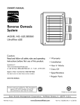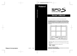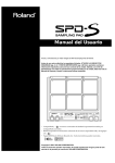
1
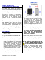
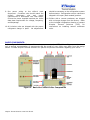
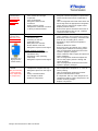
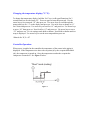
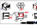
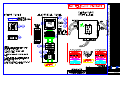
At Dimplex Thermal Solutions we are aware that our success depends on your satisfaction. We thank you for the confidence you have displayed in our company through your recent purchase of a Dimplex Thermal Solutions chiller. The unit is designed with your specific needs in mind to provide years of service and ongoing satisfaction. It has been thoroughly tested in our plant prior to shipping and stands ready to exceed expectations. Please thoroughly review the enclosed materials before installation or operation. These pages contain detail regarding suggested fluids, start-up/maintenance operation and controls applications. They will guide you through the important steps of making this purchase part of your process. As always, we stand by our product and should you require clarification or service please call us at: 1-800-YOU-KOOL (968-5665) or 269-349-6800 AIR COOLED CHILLER INSTALLATION and OPERATION MANUAL TABLE OF CONTENTS General Information 3 Installation 3 Basic Chiller Components 4 Pre-Startup Procedure 5 Initial Startup & Operation 5 Maintenance / Spare Parts 6 Fluid Recommendations 7 Troubleshooting 9 Warranty Procedures 11 Warranty 12 Unit Specific Information: 14 MSDS Temperature Controller Guide Drawings Dimplex Thermal Solutions 1800-YOU-KOOL GENERAL INFORMATION REGARDING DESIGN TEMPERATURE Our custom chiller systems are designed to maintain the temperature of cooling fluids within a selected temperature range. Each of our units is tested through monitored operation within design parameters. technicians This to enables calibrate our all experienced instrumentation precisely to the customers needs and verify that each individual unit will function as specified. Figure 1. Minimum Installation Clearances Supporting test data is enclosed either in digital 5. Connect fluid lines to the proper fittings from the process to the chiller marked “FLUID INLET TO CHILLER” and “FLUID OUTLET FROM CHILLER”. Make sure that the flow of fluid to and from the unit can not be shut off or blocked while the chiller is in operation. Piping size should be large enough to match the fluid flow conditions, generally the size of the fittings on the chiller. format or in print. The units are designed to operate efficiently within given parameters. Due to varying heat exchange rates outside of design temperature, it is highly recommended that the machine operate only at temperatures within 10°F of the specified temperature. Consult the factory if a process requires changes in excess of 10°F in either direction of design temperature. INSTALLATION: 1. Read and follow all information included with the chiller manual. 2. Read and understand all warning labels and tags on the chiller before installation. 3. Ensure the unit is placed on a flat, level, hard surface. Unless the chiller has been built for outdoor operation, it must be placed indoors. Space above and around the unit must be capable of dissipating the heat rejected by the chiller and allow room for servicing. Keep the unit at least 3ft away from walls or other objects and allow full access to all openings and electrical enclosures. At a minimum, 8ft of clearance is required above the unit for proper air circulation around the chiller as shown in Fig 1. 4. Chillers with solid feet should be secured using the provided mounting holes if possible. Units that have caster wheels should be locked to ensure the chiller does not move around. Dimplex Thermal Solutions 1800-YOU-KOOL 6. Fill the process plumbing and, if applicable, the chiller reservoir with the proper type and amount of fluid. Check with the manufacturer of the process equipment for specific fluid requirements. Refer to the “Process Fluid Recommendations” section of the manual for information on using water in the chiller. 7. Purge any air out of the fluid system to ensure that the pump suction is flooded. If possible, bleed any air trapped in the pump by opening the vent plug at the top of the pump until no more air comes out and fluid is present in the pump cavity. DO NOT ALLOW THE FLUID PUMP TO RUN DRY. THIS WILL DAMAGE THE PUMP SEALS AND WILL NOT BE COVERED UNDER WARRANTY. 8. Connect any communication wiring between the chiller and process equipment including remote controls and interlocks. All communication and remote wiring is to be provided by the customer. Refer to the chiller’s electrical prints for information on wiring locations. 9. Run power wiring to the chiller’s main disconnect. Conductor size should match the chiller’s disconnect size and power requirements in accordance with local codes. Ensure the power supplied matches the chiller data plate requirement for voltage, frequency, and amperage. 10. All inclusive units are shipped with the proper refrigerant charge in place. No adjustments should be necessary to the refrigeration system before startup. Refrigeration service valves are shipped in the open (back-seated) position. 11. Chillers with a remote condenser are shipped with a nitrogen charge from the factory. Refer to the included refrigeration drawing or contact Dimplex Thermal Solutions (DTS) for instructions on installing remote condenser units. BASIC COMPONENTS: Refer to Figure 2 for identification of the main parts on a standard DTS chiller. Please note that this is only a general representation of components and the model of your chiller may differ from the design shown. Contact Dimplex Thermal Solutions for specific component information regarding your chiller. Figure 2. Basic Air-Cooled Chiller Components Dimplex Thermal Solutions 1800-YOU-KOOL PRE-STARTUP PROCEDURE: 1. Complete all steps of the installation process before applying power to the chiller. 2. If the unit is equipped, ensure the system switch is in the OFF position, then turn on the main power disconnect. The temperature controller will turn on and automatically go into a self-test. When the self-test is complete, the controller will begin to monitor the process fluid. 3. For units that run on three-phase power, motor rotation must be checked and corrected to avoid damaging the chiller and voiding the warranty. If the chiller is equipped with a phase protector, the unit will not start up and may display a fault if phase rotation is not correct. Correcting phase rotation should make this fault go away. Single phase units will not be affected by any certain phase rotation and should continue on with step 4 of the pre-startup procedure. If the unit is equipped with a process fluid pump, phase rotation can be checked by briefly turning on the system and allowing the pump to energize. Watch the rotation of the cooling fan on the pump to see that it is turning in the direction indicated by the rotation arrow on the pump motor. Do not use condenser fans to judge phase rotation as many three phase units have single phase fans and will run correctly from DTS even with incorrect power phasing. If the unit does not have a pump or any other visual method of checking rotation, a phase checking device can be used to check power at the disconnect. All components of the chiller are wired to operate with a “right-hand” phase rotation. If you do not have a phase checking device, a certified refrigeration technician should be utilized to monitor refrigerant pressures as the chiller compressor comes online. All motors within the chiller are synchronized at the factory for proper rotation. If one motor is turning in the wrong Dimplex Thermal Solutions 1800-YOU-KOOL direction, all other motors will as well. DO NOT change the orientation of any motor leads within the chiller. If phase rotation is incorrect, shut off the power feed and change any two incoming power leads BEFORE the main disconnect. 4. Chillers two tons or larger are equipped with a compressor crankcase heater. These units must have power supplied to the unit with only the disconnect switch on for 8 hours prior to starting the chiller. This will raise the temperature of the compressor oil enough to vaporize any refrigerant that may be in the crankcase oil. Failure to allow this warm-up can result in compressor damage. 5. Ensure all process fluid lines and shutoff valves are open and the system is able to flow freely. Re-check the fluid level in the system before continuing with the startup. INITIAL STARTUP & OPERATING PROCEDURE: 1. Complete all steps of the pre-startup procedure before starting the chiller process. 2. Before turning on the chiller system, become familiar with the operation of the temperature controller on the chiller. Refer to the temperature controller guide in this manual for instructions. 3. Turn on the chiller process by moving the selector switch to either ON or LOCAL. If the unit is wired to start remotely, turn the selector switch to REMOTE and start the chiller from the other location. Chillers that do not have a process selector switch or remote control should begin the chilling process as soon as the disconnect switch is turned on. 4. If the unit is equipped with a process pump, it will energize and produce flow as soon as the chiller is turned on. Monitor any system pressure gauges and make note of initial pressures. The pump may need to run for several minutes to allow any air to be worked out of the system before regular flow is established. Any fluid bypass valves in the system should be factory set according to customer specifications but may need slight adjustment in the field. Consult the factory before making any adjustments to the system. 5. Check the entire fluid system for leaks and ensure there is flow throughout the system. 6. After the pump turns on, the temperature controller will then analyze the process fluid temperature and determine whether or not cooling is needed. If the fluid temperature is above setpoint, the refrigerant compressor will commence and begin cooling the fluid. 7. Monitor the chiller to ensure it is performing as designed. The chiller should be able to maintain the desired fluid setpoint under a full load from the process. Slight adjustments may be necessary according to your specific process. Please consult a technician at Dimplex Thermal Solutions before making any changes to the unit. 8. To turn off the chiller process, move the selector switch to the OFF position. With the selector OFF, the temperature controller display will be on to monitor the process, but indicate the system is off. Keep the chiller’s main power-disconnect ON even when the chiller is not in use, unless it is used to turn the chiller process off and on. This keeps the power to the crankcase heater and prevents compressor damage when starting again. If the unit is equipped with a fluid maintenance heater, the heater will operate if the fluid falls below the factory setpoint and will operate with the selector switch off. Dimplex Thermal Solutions 1800-YOU-KOOL MAINTENANCE AND SPARE PARTS: Proper maintenance is the key to extending the life of your chiller. Routine checks and a watchful eye will minimize costly repairs and down time. Establish a regular schedule of maintenance depending on the amount the chiller is used and the environment in which it is used. Environments that are very dirty or dusty will require more attention than ones that maintain a cleaner atmosphere. This list of maintenance items will help to ensure an operational chiller: 1. Inspect and clean condenser / air filters Excessive buildup of dirt, oil, and other debris on the condenser coil will cause refrigerant pressures to increase and not allow the unit to perform to its full capacity. Ensure the fins of the condenser are clean and not damaged to keep airflow at a maximum. Use compressed air at no more than 30PSI to blow out the condenser in the opposite direction of air flow. If the unit is equipped with air filters, clean them with compressed air or wash them out with water and allow drying before reinstallation. 2. Check water quality/glycol mixture The process fluid should be clean and free of contaminants. If the chiller has a reservoir, check for debris or contaminants which could reduce the efficiency of your chiller. Check for normal inlet and outlet fluid pressures through the chiller. A large pressure differential could indicate a plugged heat exchanger or dirty tank. Test the process fluid to ensure proper freeze and corrosion protection in accordance with original design specifications. Do not test the process fluid from the sight glass due to the lower turnover at that location. 3. Inspect fluid filters Fluid filters should be clean enough to allow for proper flow and pressure in the system. An increased fluid pressure on the system may indicate a dirty filter. Replacement of fluid filters should be done at regular intervals to keep the fluid system clean and free flowing. Inspect fluid filters shortly after initial start-up of the chiller and establish a basis for how frequently they may need to be changed in the future. 4. Inspect fluid system Visually check for fluid leaks throughout system. Physically check for loose pipe fittings or hoses. Ensure that no plumbing parts are wearing, cracking, or chafing. 5. Check voltage & amp draws Check for proper incoming voltage and current draws on all motors and heaters. Refer to the chiller’s electrical schematics or the motor nameplate for proper voltage and amperage ratings. Readings should be within +/- 10% of the nameplate and have a maximum difference of +/- 2% between each phase. 6. Inspect mechanical components Check mechanical components of the chiller for signs of wear or over-heating. Metallic sounds or other excessive noise could indicate a problem with the chiller. Discolored paint or metal could be a sign of a motor under excessive load and over-drawing current. Keep all components with lubrication fittings properly filled according to the nameplate data or information tag. 7. Check all wiring Ensure the chiller’s main power disconnect is OFF. Check the electrical box and all junction boxes for any loose or damaged wiring. Replace any wiring that could cause problems with shorting or unintentional grounds. 8. Inspect/test refrigeration system Check the inside of the chiller for evidence of refrigerant leaks. Spots of oil inside of the chiller or refrigeration lines covered in oil could indicate a possible leak. Have a certified refrigeration technician check the refrigeration system for proper operation. The technician should leak check the unit, monitor operating pressures, and adjust as needed. For more information, contact the DTS Service Department 24 hours a day at 1800-YOU-KOOL. Be sure to have model and serial number ready when calling. To purchase spare parts and regular maintenance items for your chiller, contact our Parts department at 1-800-YOU-KOOL. PROCESS FLUID RECOMMENDATIONS: Dimplex Thermal Solutions 1800-YOU-KOOL For recommendations on the correct process fluid to use in your chilling system, refer to the manufacturer of the equipment served by the chiller. Most manufacturers have a specified type of fluid for correct system operation. This document should serve as a guide only when using a glycol and water mixture for the heat transfer fluid. USING WATER FOR CHILLER PROCESS: Dimplex Thermal Solutions recommends the use of an industrial inhibited glycol and water mixture in its water chiller systems. The main job of glycol is to prevent freezing of the process fluid and ensure consistent flow at the operating temperature. Inhibited glycols will also prevent formation of scale and corrosion while protecting metals such as brass, copper, steel, cast iron, and aluminum. Water systems treated with inhibited glycol will also be protected from algae and bacteria that can grow and degrade the fluid system performance. Ethylene and Propylene are the two standard types of inhibited glycols that can be used in DTS chillers. Do not mix different types or brand names of glycol as this can result in some inhibitors precipitating out of the solution. Do not use automotive grade anti-freeze in the chiller process. These types of glycols are not designed for industrial applications and may cause problems with heat transfer or fluid flow. Many automotive glycols contain silicate-based inhibitors that can coat heat-exchangers, attack pump seals, or form a flow restricting gel. Check state and local codes when selecting the process fluid. Certain areas may have environmental regulations concerning the use and disposal of glycol or other additives. ETHYLENE GLYCOL: Ethylene glycol is the standard heat-transfer fluid for most industrial applications. This type of glycol can be used in any application where a low-toxicity content is not required. Ethylene glycol has moderately acute oral toxicity and should not be used in processes where the fluid could come in contact with potable water, food, or beverage products. PROPYLENE GLYCOL: Propylene glycol maintains generally the same freeze protection, corrosion and algae prevention as ethylene glycol, but has a lower level of toxicity. This type of glycol is more readily disposable than ethylene and safer to handle. Propylene glycol is commonly used in the food industry and in applications where the user may come in frequent contact with the fluid. Dimplex Thermal Solutions recommends the use of K-Kool Glycols in its units. WATER: When selecting the water to mix with the glycol, use a good quality, filtered source that meets the requirements of the process machine manufacturer. Dimplex Thermal Solutions recommends the use of distilled or reverseosmosis water for the water / glycol mixture. De-ionized water can be used to fill the chiller process initially, but should not be maintained to a de-ionized state thereafter. Unless the chiller has been ordered and designed for the use of water that is continually de-ionized, the fluid will actually attack certain metals within the chiller and cause damage to some components. Damage caused by the use of maintained de-ionized water in a chiller not designed for it will not be covered under warranty. Consult DTS before continuously using de-ionized water to check for compatibility. The use of regular tap water is not recommended. Water from the “city” or “ground” contains deposits and additives which can decrease component life and increase maintenance time. GLYCOL / WATER MIXTURES: The location of the chiller and environmental concerns must be taken into account when selecting the proper mixture of glycol and water for the chiller process. A process which is located completely indoors and has no chance of freezing will require less glycol than a system located outdoors where low temperatures can cause the fluid to freeze and piping to burst. Applications that have a low operating temperature (below 30°F) should use a glycol mixture equivalent to an outdoor system. After selecting the proper glycol and water types, use the following chart to determine the recommended mixture depending on application and location of the process. The glycol percentage figures in the chart below will apply to any brand of ethylene or propylene glycol. APPLICATION GLYCOL % WATER % FREEZE PROTECTION* BURST PROTECTION* Indoor chiller and process 30 70 5°F / -15°C -20°F / -29°C Outdoor chiller / Low fluid temperature system (<30°F) 50 50 -35°F / -37°C -60°F / -60°C * Figures based on performance of DTS “K-Kool-E” brand of Ethylene Glycol. FLUID MAINTENANCE / FILTRATION: Maintaining clean process water and the proper glycol content will extend the life of the system and reduce costly down-time. If the chiller was not equipped with a fluid filter from the factory, it is highly recommended to install some sort of filtering system to remove unwanted dirt and debris. Refer to the Chiller Maintenance section of the manual for water and filter maintenance information. Dimplex Thermal Solutions 1800-YOU-KOOL TROUBLESHOOTING GUIDE: This guide should serve as a general outline for troubleshooting issues with all Dimplex Thermal Solutions chillers. Due to the various models of DTS chillers, the items listed in possible causes may not apply to every DTS chiller. Contact the DTS customer service department for assistance at 1-800-YOU-KOOL Refer to the Warranty Procedures section of this manual before having any work performed on units that are under warranty. PROBLEM POSSIBLE CAUSE CORRECTIVE ACTION Chiller will not turn on. (No display on temperature controller) Chiller turns on but nothing happens. (Display is on but no pump or cooling cycle) No power to chiller. Main disconnect turned off. Blown fuses. Tripped starter overloads. Check power feed to chiller. Turn on main disconnect. Check for and replace blown fuses. Reset any tripped overloads. Selector switch not turned on. Remote signal not active. Fault present within chiller. Fluid pump not operating. Blown fuses. Phase rotation incorrect. Fluid pump is on but does not create required pressure or flow. (Flow fault) No fluid present at pump suction. Pump discharge closed or blocked. Fluid is dirty / dirty filters. Fluid line size too small. Pump / fluid system is air-bound. Phase rotation incorrect. Fluid temp is below setpoint. Inadequate fluid flow. Low refrigerant pressure. High refrigerant pressure. Compressor overload tripped. Compressor lube protector tripped (If equipped). Blown fuses to compressor. Faulty temp controller output. Bad compressor. Fault present within chiller. Phase rotation incorrect. Fluid or heat exchanger is dirty. Loss of flow or fluid level. Low refrigerant pressure. Ambient temperature too high. Heat load exceeds chiller’s capacity. Turn selector switch to ON or LOCAL. Check remote connection for signal. Determine fault and clear if possible. Check pump overload and power to contactor. Check and replace fuses. Correct phase rotation at main disconnect. Check fluid level and ensure there is fluid at the pump’s suction. Ensure all fluid lines are open to flow. Clean fluid and change filters. Up-size fluid lines outside of chiller. Vent pump cavity to flood the suction. Correct phase rotation at main disconnect. Allow fluid system to increase in temperature. Correct fluid system to establish flow. SEE “Low refrigerant fault” section. SEE “High refrigerant fault” section. SEE “Compressor overload” section. Reset lube protector. Check and replace blown fuses. Consult DTS customer service department. Consult DTS customer service department. Determine fault and clear if possible. Correct phase rotation at incoming power. Replace fluid and clean fluid system. Check fluid system for free flow and ensure chiller has adequate fluid level. Restart chiller or clear fault on controller. SEE “low refrigerant fault” section. Ensure chiller is operating within its designed ambient temperature specification. Reduce heat load to chiller if possible. Check the factory specifications to ensure the chiller is not being operated more than +/- 10°F of the original temperature setpoint or fluid flow. Fluid pump is operational but the refrigerant compressor will not run. Chiller is running but does not maintain the desired fluid temp. Dimplex Thermal Solutions 1800-YOU-KOOL Low refrigerant pressure fault (Automatically reset when satisfied with pressure) Low ambient air temperature. Loss of fluid flow through evaporator. Loss of refrigerant. Refrigerant solenoid not functional. Faulty pressure switch. Compressor crankcase not warm or faulty crankcase heater. AIR COOLED CHILLERS: Air filters dirty. Condenser dirty. Incoming air too hot. Inoperative fans. Back panel out of chiller. Phase rotation incorrect. Refrigerant system overcharged. High refrigerant pressure fault (Manually reset inside of chiller) (Example of a high pressure switch shown) Compressor overload (May be manually or automatically reset, depending on compressor) WATER COOLED CHILLERS: Low water flow to condenser. Condenser dirty. Regulating valve operating incorrectly. Refrigerant system overcharged. Compressor running too hot. Temperature setpoint too high. Refrigerant pressures too high or low. Faulty overload module. Low voltage to chiller. Defective compressor. Dimplex Thermal Solutions 1800-YOU-KOOL Ensure chiller is operating within its designed ambient temperature specification. Check fluid flow and ensure evaporator is clean. Have a refrigerant technician leak check unit and charge with the appropriate refrigerant. Check wiring to solenoid or replace valve. Replace pressure switch. Ensure main power disconnect has been on for at least 8 hours prior to use. Replace crankcase heater if faulty. Clean filters (See maintenance section). Clean condenser (See maintenance section). Ensure the chiller is properly ventilated with fresh air not exceeding 90°F, unless designed for high-ambient temperature operation. Check for blown fan fuses. Ensure all covers and panels are in chiller. Correct phase rotation at incoming power. Have a refrigeration technician ensure the system is properly charged. Check condenser water supply and pressure. Clean condenser. Have a refrigeration technician adjust the valve to the proper pressure setting and check operation. Have a refrigeration technician ensure the system is properly charged. Allow compressor to cool, then restart unit. Move temperature setpoint to +/- 10°F of factory setting. Have a refrigeration technician monitor pressures and determine cause. If compressor will run, check amp draw on compressor leads to verify compressor is ok. Correct incoming voltage. Replace compressor. GENERAL WARRANTY PROCEDURES: WARRANTY WORK: Before doing any work on a chiller covered under warranty, call Dimplex Thermal Solutions (DTS) and explain the problem to one of our service technicians who can then determine the best course of action. DTS will not be obligated to pay for warranty service performed without our prior approval. Refer to the Warranty section of this manual on the specific terms of warranty for your chiller. Please Note: It is the service contractor’s responsibility to enclose a service report/work order with each invoice. Unless pre-authorized for special circumstances, DTS will not honor invoices for work done by two or more people at a time, or for overtime labor charges. If the customer requests work that falls into either of these categories, the customer is responsible for the extra charges incurred. WARRANTY PARTS: All replacement parts under warranty must come from Dimplex Thermal Solutions. When it is necessary for DTS to replace parts which are under warranty, we will issue a Returned Goods Authorization (RGA) for all parts we wish to have shipped back to our factory, freight prepaid. RGA’s are valid for a period of thirty (30) days. If DTS has not received the requested parts by the expiration date, the customer will be invoiced for the replacement cost at that time. Please Note: While DTS is willing to pay freight charges one way for replacement parts, special freight charges such as next day service, Saturday delivery, etc, are not included. If the customer requests one of these special services, they are responsible for the charges incurred. ______________________________________ DIMPLEX THERMAL SOLUTIONS 2625 Emerald Drive Kalamazoo, MI 49001 1-800-YOU-KOOL (1-800-968-5665) Dimplex Thermal Solutions 1800-YOU-KOOL WARRANTY WARRANTY OF WORKMANSHIP AND MATERIALS THE IMPLIED WARRANTIES OF MERCHANTABILITY AND OF FITNESS FOR A PARTICULAR PURPOSE AND, EXCEPT AS SPECIFICALLY SET FORTH HEREIN, ALL OTHER WARRANTIES AND REPRESENTATIONS, EXPRESSED OR IMPLIED, ARE HEREBY DISCLAIMED AND EXCLUDED BY THIS AGREEMENT. THERE ARE NO WARRANTIES THAT EXTEND BEYOND THE DESCRIPTION HEREOF. SELLER’S WARRANTIES HEREIN APPLY ONLY TO THE ORIGINAL PURCHASER AND DO NOT EXTEND, EXPRESSLY OR BY IMPLICATION, TO ANY OTHER PERSON OR PERSONS. Seller guarantees all North American installed equipment and materials of its manufacture or start-up services performed by Seller against defects in workmanship and material—under normal and intended use, service, maintenance and proper installation—for a period of twelve (12) months as to Schreiber Brand Chillers and eighteen (18) months for Koolant Kooler Brand Chillers from date of shipment. Equipment installed outside of North America will be warranted for parts only, standard delivery shipment. The Seller obligation under this agreement is limited solely to repair or replacement at Seller’s option, in Seller’s factory or in the field, with Seller approval, within said warranty period. If the equipment is returned to Seller’s factory, the unit must be returned freight prepaid, with prior approval from Seller, with Buyer having obtained a returned goods authorization (RGA) number from Seller. Seller will make any needed repairs at no charge to Buyer if the damage is determined not to be the fault of the Buyer. Seller will then return the equipment to Buyer freight prepaid; in other words, Seller will be responsible for one leg of the transportation costs. The above warranty shall not apply to any equipment, or components thereof, which have been subject to abnormal or improper use, negligence (including failure to maintain the equipment as recommended in writing by Seller) or accident or which have been altered or repaired by other than Seller or Seller’s authorized representative. Nothing shall be construed as an additional warranty unless specifically designated as such in writing and signed by Seller (“Additional Warranty”). The Additional Warranty shall be subject to the provision of this document as to duration and limitation of remedy, unless the Additional Warranty expressly amends such provisions. The above warranty shall not apply to any parts sold independently of the unit sold. All parts sales are subject to ninety (90) day warranty. (Effective Date 7-5-2012) The solution to all your cooling needs 2625 Emerald Drive, Kalamazoo, MI 49001 www.dimplexthermal.com Phone: 800.968.5665 or 269.349.6800 Fax: 269.349.8951 DuPont Chemicals 2187FR Revised 12-APR-1996 Printed 19-AUG-1997 "SUVA" 134A CHEMICAL PRODUCT/COMPANY IDENTICICATION Material Identification Corporate MSDS Number CAS Number Formula CAS Name Tradenames and Synonyms HCF 134A VT1505 DU000693 811-97-2 CH2FCF3 " SUVA " 134A Company Identification MANUFACTURER / DISTRIBUTOR DuPont 1007 Market Street Wilmington, DE 19898 PHONE NUMBERS Product Information Transport Emergency Medical Emergency 1-800-441-7515 CHEMTREC: 1-800-424-9300 1-800-441-3637 COMPOSITION/INFORMATION ON INGREDIENTS Components Material CAS Number % *ETHANE, 1 , 1 , 1 , 2-TETRAFLUORO- 811-97-2 100 (HFC-134a). (Continued) 1 HAZARDS IDENTIFICATION Potential Health Effects INHALATION ETHANE, 1,1,1,2-TETRAFLUOROGross overexposure may cause: Central nerous system depression with dizziness, confusion, incoordination, drowsiness or unconsciousness. Inhalation of high concentrations of vapor is harmful and may cause heart irregularity unconsciousness or death. Intentional misuse or deliberate inhalation may cause death without warning. Vapor reduces oxygen available for breathing and is heavier than air. Liquid contact can cause frostbite. HUMAN HEALTH EFFECTS: SKIN CONTACT ETHANE, 1,1,1,2-TETRAFLUOROImmediate effects of overexposure may include frostbite. If liquid or escaping vapor contacts he skin. Frostbite-like effects may occur if the liquid or escaping vapors contact the eyes. Inhalation may include temporary nervous system depression with anesthetic effects such as dizziness, headache, confusion, incoordination, and loss of consciousness. Higher exposures may lead to temporary alteration of the heart's electrical activity with irregular pulse, palpitations, or inadequate circulation. Fatality may occur from gross overexposure. Individuals with preexisting diseases of the central nervous or cardiovascular system may have increased susceptibility to the toxicity of excessive exposures. CARCINAGENICITY INFORMATION None of the components present in this material at concentrations equal to or greater than 0.1% are listed by IARC, NTP, OSHA or ACGIH as a carcinogen. FIRST AID MEASURES First Aid INHALATION If inhaled, immediately remove to fresh air. Keep person calm. If not breathing, give artificial respiration. If breathing is difficult, give oxygen. Call a physician. SKIN CONTACT In case of contact, immediately flush area with plenty of lukewarm water for at least 15 minutes, while removing contaminated clothing and shoes. Call a physician. Wash contaminated clothing before reuse. Treat for frostbite if necessary by gently warming affected area. EYE CONTACT In case of contact, immediately flush eyes with plenty of water for at least 15 minutes. Call a physician. 2 (2008FR) (continued) FIRST AID MEASURES CONTINUED, INGESTION Ingestion is not considered a potential route of exposure. Notes to Physicians Because of possible disturbances of cardiac rhythm catecholamine drugs, such as epinephrine should only be used with special caution in situations of emergency life support. FIRE FIGHTING MEASURES Flammable Properties Flash Point LEL UEL Autoignition Will not burn Not Applicable Not Applicable >743 C (>1369 F) HFC-134A is not flammable at ambient temperatures and atmospheric pressure. However, HFC134A has been shown in tests to be combustible at pressures as low as 5.5 psig at 177 C (351 F) when mixed with air at concentrations of 60 volume % air. At lower temperatures, higher pressures are required for combustibility. Experimental data have also been reported which indicate combustibility of HFC 134A in the presence of certain concentrations of chlorine. FIRE AND EXPLOSION HAZARDS: Cylinders may rupture under fire conditions. Decomposition may occur. Contact of welding or soldering torch flame with high concentrations of refrigerent can result in visible changes in the size and color of the torch flame. This flame effect will only occur in concentrations of product well above the recommended exposure limit, therefore stop all work and ventilate the area before proceeding. Use forced ventilation to disperse refrigerant vapors from the work area before using any open flames. Extinguishing Media As appropriate for combustibles in area. Extinguishant for other burning material in area is sufficient to stop burning. Fire Fighting Instructions Cool tank/container with water spray. Self-contained breathing apparatus (SCBA) is required if cylinders rupture or contents are released under fire conditions. 2008FR (Continued) 3 ACCIDENTAL RELEASE MEASURES Safeguards (Personnel) NOTE: Review FIRE FIGHTING MEASURES and HANDLING (PERSONNEL) sections before proceeding with clean up. Use appropriate PERSONAL PROTECTIVE EQUIPMENT during clean up. Accidental Release Measures Ventilate area, especially low or enclosed places where heavy vapors might collect. Remove open flames. Use self-contained breathing apparatus (SCBA) for large spills or releases. HANDLING AND STORAGE Handling (Personnel/Physical Aspects) Use with sufficient ventilation to keep employee below recommended limits. HFC-134A should not mixed with air for leak testing. In general it should be used or allowed to be present with high concentration air above atmospheric pressure. See Flamable Propertiessaction. Contact with chlorine or other strong oxidizing agents should also be avoided. Storage Store in a Clean, dry area. Do not heat above 52 C (126 F) EXPOSURE CONTROLS/PERSONAL PROTECTION Engineering Controls Normal ventilation for standard manufacturing procedures is generally adequate. Local exhaust should be used when large amounts are released. Mechanical ventilation should be used in low or enclosed places. Refrigerant concentration monitors may be necessary to determine vapor concentrations in work areas prior to use of torches or other open flames, or if employees are entering enclosed areas. PERSONAL PROTECTIVE EQUIPMENT Impervious gloves and chemical splash goggles should be used when handling liquid. Under normal manufacturing conditions, no respiratory protection is required when using this product. Selfcontained breathing apparatus (SCBA) is required if a large release occurs. EXPOSURE GUIDELINES EXPOSURE LIMITS “SUVA” 134A PEL (OSHA) TLV (ACGIH) AEL * (DuPont) WEEL (AIHA) None Established None Established 1,000 ppm, 8 & 12 Hr. TWA 1000 ppm, 8 Hr. TWA * AEL is DuPont's Acceptable Exposure Limit. Where governmentally imposed occupational exposure limits which are lower than the AEL are in effect, such limits shall take precedence. 2008FR (Continued) 4 PHYSICAL AND CHEMICAL PROPERTIES PHYSICAL DATA Boiling Point Vapor Pressure Fl Vapor Density Fl % Volatilize Solubility in Water Odor Form Color Liquid Density -26.5 C (15.7 F) @ 736 mm Hg 96 psig @ 25 C (77 F) 3.6 (Air=l.O) @ 25 C (77 F) 100 WT% 0.15 WT%, @ 25 C (77 F) @ 14.7 psia Slight ethereal Liquefied Gas. Clear, Colorless. 1.21 g/cm3 @ 25 C (77 F) STABILITY AND REACTIVITY CHEMICAL STABILITY Material is stable. However, avoid open flames and high temperatures. CONDITIONS TO AVOID Avoid open flames and high temperatures. INCOMPATIBILITY WITH OTHER MATERIALS Incompatible with alkali or alkaline earth metals- powdered Al, Zn, Be, etc. DECOMPOSITION Decomposition Products are hazardous. HCFC-134A can be decomposed by high temperatures (open flames, glowing metal surfaces, etc.) forming hydrochloric and hydrofluoric acids, and possibly carbonyl halides. POLYMERIZATION Polymerization will not occur. TOXICOLOGICAL INFORMATION ANIMAL DATA ETHANE, 1,1,1,2-TETRAFLUORO INHALATION: 4 hour, ALC, rat: 567,000 ppm. SKIN: The compound is a skin irritant and a slight eye irritant but is not a skin sensitizer in animals. EYE: A short duration spray of vapor produced very slight eye irritation. Effects from single high exposures include central nervous system depression, anesthesia, rapid breathing, lung congestion and microscopic liver changes. Cardiac sensitization occurred in dogs at 50,000 ppm or greater from the action of exogenous epinephrine. 5 No toxic effects or abnormal histopathological observations occurred in rats repeatedly exposed to concentrations ranging from 10,000 to 50,000 ppm (v/v). Long-term exposures to 50,000 ppm (v/v) of vapors produced organ weight increases and a decrease in body weight gain, but no increased mortality or adverse hematological effects, In chronic inhalation studies, HCFC-22, at a concentration of 50,000 ppm (vlv), produced a small, but statistically significant increase of lateoccurring tumors involving salivary glands in male rats, but not female rats or male or female mice. In the same studies, no increased incidence of tumors was seen in either species at concentrations of 10,000 ppm or 1,000 ppm (v/v). Long-term administration in corn oil produced no effects on body weight or mortality. HCFC-22 was mutagenic in some strains of bacteria in bacterial cell cultures, but not mammalian cell cultures or animals. It did not cause heritable genetic damage in (Continued) 2008FR (Continued) TOXICOLOGICAL INFORMATION (Continued) mammals. Single exposure caused: Cardiac sensitation, a potentially fatal disturbance of heart rhythm associated with a heightened sensitivity to the action of epinephrine. Lowest-Observed-AdverseEffect-Level for cardiac sensization: 75,000 ppm. Single exposure caused: Lethargy. Narcosis. Incrased respiratory rates. These effects were temporary. Single exposure to near lethal doses caused: Pulmonary edema. Repeated exposure to caused: Increased adrenals, liver, spleen weight. Decreased uterine, prostate weight. Repeated dosing of higher concentrations caused: the following tempoerary effects- Tremors. Incoordination. CARCINOGENIC, DEVELOPMENTAL, REPRODUCTIVE, MUTAGENIC EFFECTS: In a two-year inhalation study, HFC-134A, at a concentration of 50,000 ppm, produced an increase in late-occuring benign testicular tumors, testicular hyperplasia and esticular weight. The no-effectlevel for this study was 10,000 ppm. Animal data show slight fetoxicity but only ECOLOGICAL INFORMATION ECOTOXICOLOGICAL INFORMATION Aquatic Toxicity: HCFC-22 48 hour EC50 - Daphnia magna: 433 mgiL DISPOSAL CONSIDERATIONS WASTE DISPOSAL 6 Comply with Federal, State, and local regulations. Reclaim Comply with Federal, State, and local regulations. Red by distillation or remove to a permitted waste disposal facility. TRANSPORTATION INFORMATION SHIPPING INFORMATION DOT/IMO Proper Shipping Name Hazard Class UN No. DOT/IMO Label CHLORDDIFLUOROMETHANE 2.2 1018 NONFLAMMABLE GAS Shipping Containers Tank Cars. Tank Trucks. Cylinders. (Continued) 2008FR (Continued) REGULATORY INFORMATION U.S. FEDERAL REGULATIONS TSGA Inventory Status Reported/Included. TITLE III HAZARD CLASSIFICATIONS SECTIONS 311, 312 Acute : Yes Chronic : No Fire : No Reactivity : No Pressure : Yes HAZARDOUS CHEMICAL LISTS SARA Extremely Hazardous Substance CERCLA Hazardous Substance SARA Toxic Chemical : : - See Components Section 7 No No OTHER INFORMATION NFPA NPCA-HMIS NPCA HMIS Health Flammability Reactivity 1 O 1 Personal Protection rating to be supplied by user depending on use conditions. The data in this Material Safety Data Sheet relates only to the specific material designated herein and does not relate to use in combination with any other material or in any process. Responsibility for MSDS Address Ø Ø Telephone : DuPont Chemicals : Engineering a Product Safety : P.O. Box 80709, Chestnut Run : Wilmington, DE 19880-0709 : (302) 999-4946 # Indicates updated section. End of MSDS 2008FR 8 Controller Operation Guide (S-Series) Keypad Functions: Figure 1 Button 1 (Up Arrow): Button 2 (Set): Button 3 (Down Arrow): Pressing this button raises the selected value. Pressing this button for 1 second allows access to the “setpoint” of the chiller. Pressing this button for 3 seconds will allow access to the “set-point differential”, “password” and “ºC/ ºF” of the chiller. Pressing this button lowers the selected value. *Note 1: Password is used to access additional parameters in the controller. This should only be accessed by a certified technician. Changing the “set-point”: To change the “set-point”, hold the “Set” key (see Keypad Functions) for 1 second until you see the letters ‘st’. Then press the set key again to access the set-point. Use the “Up Arrow” and “Down Arrow” keys to change the value. Once to the desired value, press the “Set” key again to store the value. *Note 2: The set-point can be set between 50ºF and 90 ºF Changing the “set-point differential”: To change the “set-point differential”, hold the “Set” key (see Keypad Functions) for 3 seconds until you see the letters ‘Ps’ (See Note 1: password is needed to save changes). The use the arrow keys to scroll through the menus until you see the letters ‘rd’. Then press the set key again to access the set-point differential. Use the “Up Arrow” and “Down Arrow” keys to change the value. Once to the desired value, press the “Set” key again to store the value. *Note 3: The set-point differential should be set between 3ºF and 10 ºF Changing the temperature display (ºC/ ºF): To change the temperature display, hold the “Set” key (see Keypad Functions) for 3 seconds until you see the letters ‘Ps’. Press set again to enter the password. Use the arrow keys to set password “22” then press set. Use arrow keys to scroll through the menus until you see ‘/5’ on the display and press set. Use arrow keys to change to “0” for Celsius and press set. Use arrow keys to scroll to “r1” and press set. Use arrow keys to set to “10” then press set. Next Scroll to “r2” and press set. Use arrow keys to set to “32” and press set. To exit settings mode hold set button. Next Hold set button until set temp is displayed. Use arrow keys to set the new temp and then press set. *Note 4: 0 = ºC, 1 = ºF Controller Operation: When power is applied to the controller the temperature of the sensor in the piping is displayed. If the temperature rises above the set-point (st) by the set-point differential (rd), the compressor is turned on. Once the temperature reaches the set-point the compressor is turned off. See Figure 2 below: Figure 2 Dimplex KOOLANT KOOLERS Thermal Solutions SCHREIBER CHILLERS Dimplex KOOLANT KOOLERS Thermal Solutions SCHREIBER CHILLERS Dimplex KOOLANT KOOLERS Thermal Solutions SCHREIBER CHILLERS Dimplex KOOLANT KOOLERS Thermal Solutions SCHREIBER CHILLERS Dimplex KOOLANT KOOLERS Thermal Solutions SCHREIBER CHILLERS Dimplex KOOLANT KOOLERS Thermal Solutions SCHREIBER CHILLERS