1
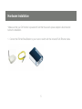
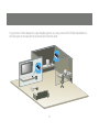
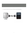
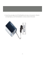
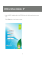
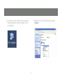
Installation Guide
DVI Net ShareStation
1
GDIP201
PART NO. M1048
2
Table of Contents
Package Contents
4
GDIP201 Configuration - Vista
Hardware Installation
5
Connect to DVI Net ShareStation – Vista
52
USB Server software installation - XP
10
Video Mode configuration - Vista
54
DisplayLink software installation XP
14
Disconnect the GDIP201 in - Vista
59
GDIP201 Full Software Installation - XP
18
Setting Polling Interval - XP
60
Windows XP utility Setup
21
Web Management Interface
61
Connecting to a DVI Monitor - XP
25
Upload Firmware
64
Video Mode configuration - XP
28
68
Disconnecting the GDIP201 - XP
34
Federal Communications Commission
(FCC) Statement
USB Server Software Installation - Vista
35
CE Statement
70
DisplayLink software installation - Vista
GDIP201 Full Software installation - Vista
39
43
3
48
Limited Warranty
71
Contact
72
Package Contents
Verify that nothing is missing from the package by using the checklist below. Please contact
your dealer if anything is missing or damaged. All packing materials are recyclable. Please
confirm the items in the package below:
1 x DVI Net ShareStation
1 x RJ45 Ethernet Cable
1 x USB Cable
1 x User Manual
1 x Installation CD
1 x Warranty/Registration Card
1 x Power Adapter
1 x US-Euro Prong Changer
1 x DVI to VGA Adapter
4
Hardware Installation
*Make sure that your DVI monitor is powered off and that the server’s power adapter is disconnected
before the installation.
1. Connect the DVI Net ShareStation to your router or switch with the included RJ45 Ethernet cable.
5
If your home or office already has a pre-installed network, you may connect the DVI Net ShareStation to
the RJ45 jack on the wall with the included RJ45 Ethernet cable.
DSL MODEM
6
2. Connect the DVI cable of the DVI monitor to the DVI port on the DVI Net ShareStation.
7
3. Connect the power adapter to the DVI Net ShareStation and make sure it is powered on. When the
Link indicator lights up, the DVI Net ShareStation is correctly connected to the network.
8
Before you start the software installation,
If this is the first time you are installing the GDIP201 software please proceed to page 18
If you had purchased the IOGEAR GUC2020D and installed DisplayLink software, then you will only need
to install the IOGEAR USB Server software.
• Please see page 10 for Windows XP installation.
• Please see page 35 for Windows Vista installation.
If you had purchased the IOGEAR GUIP201 and installed the IOGEAR USB Server software installed, then
you will only need to install the DisplayLink software.
• Please see page 14 for Windows XP installation.
• Please see page 39 for Windows Vista installation.
9
USB Server Software Installation - XP
1. Insert the GDIP201 installation disk into the CD-ROM drive, which will bring up the auto run screen
menu.
Click the Exit button to close the auto run screen.
10
2. Go to My Computer which can be located by
double clicking on the My Computer icon on
your desktop.
3. Right click on the CD-ROM drive and select
Explore.
11
4. Double click on the folder that corresponds
to your operating system.
Double click on the setup icon to install the
IOGEAR utility.
12
5. The installation wizard will start the
installation process, click “Next” to
continue.
6. When the installation completes, click
“Finish” to close the installation wizard.
13
DisplayLink- software installation XP
2. Go to My Computer which can be located by
double clicking on the My Computer icon on
your desktop.
1. Insert the GDIP201 installation disk which will
bring up the auto run screen menu.
Click the Exit button to close the auto run
screen.
14
3. Right click on the CD-ROM drive and select
Explore.
4. Double click on the DL_Driver folder
15
6. The installation program will start, click
I Accept to continue
5. To start the DisplayLink software installation
you will need to double click on the Setup
icon.
16
7. The DisplayLink software is now installing
17
GDIP201 Full Software Installation - XP
2. The installation wizard will start the
installation process, click “Next” to
continue.
This section will guide you through the
complete GDIP201 software installation.
1. Insert the Software CD into your computer.
A splash screen should appear with a
menu of options. Click on “Windows
XP installation” to set up the DVI Net
ShareStation’s control center software.
18
3. When the installation completes, click
“Finish” to close the installation wizard
19
DisplayLink installation
4. To start the DisplayLink installation, click
I Accept to continue
5. The DisplayLink software is now installing
20
Windows XP Utility Setup
1. Once you have completed both the IOGEAR
and the DisplayLink software installation you
will be ready to use the GDIP201.
You will find a new icon on your desktop called
“Launch IOGEAR USB server”, double click
the icon and it will bring up the IOGEAR USB
server configuration utility.
21
3. Click on “Install the software automatically (Recommended)” and click Next to
continue.
2. Once the IOGEAR utility is launched,
Windows will prompt you with a “Found
New Hardware Wizard” window. You will
need to complete the wizard so that you will
be able to use the DVI Net ShareStation on
your computer
Select “No, not this time” and click on
Next to continue.
22
4. Windows will install the necessary drivers for
the DVI Net ShareStation.
5. Select Finish to complete the wizard.
23
6. Once you are finished with the Found New
Hardware Wizard, the IOGEAR utility will
show up and display the active GDIP201
DVI Net ShareStations connected on your
network. In this screen, you will see the
product listed as “IOGEAR GDIP201 –
334458 (192.168.10.74)”. The “334458” is
the last 6 digits of the device’s MAC address,
and the “192.168.10.74” is the device’s IP
address.
24
Connecting to a DVI Monitor - XP
1. The GDIP201 DVI Net ShareStation will
show up on the IOGEAR USB Server utility
software. Underneath the GDIP201, there
will be a green icon indicating that the DVI
Net ShareStation is available and ready to
be connected. If for any reason the GDIP201
device does not show up, please click the
SEARCH button to refresh the utility.
Note: If the DVI Net ShareStation does not show
up on the list, please try to disconnect and
reconnect the device.
25
2. Select “DisplayLink USB Display Adapter
(DVI)” and click the “Connect” button.
3. Once connected, the green icon will turn
orange to indicate that the connection has
been established.
26
4. After you have connected the GDIP201, the DisplayLink icon will show up in the taskbar, as shown
27
Video Mode Configuration – XP
When the DVI adapter first connects, the default setting is in extension mode. You may change the
screen mode and the operation mode under the Windows display properties.
Go to Control Panel and double click “Display.”
Choose “Settings” tab.
There are two options to adjust the Resolution, Color Quality, Screen Rotation, and Extended or Mirror
Mode. One is to click on the DisplayLink icon in the task bar another is to go to Control Panel, double
click on “Display,” then choose settings tab.
28
Note: If no output is seen on the monitor connected to the DVI adapter, it may be in a mode which cannot
be displayed by the monitor. This can happen if the monitor does not have its supported modes to the
DVI adapter. Reduce the resolution of the primary display until an image is shown.
29
Mirror Mode
Mirror mode duplicates the primary display to
the monitor connected to the DVI adapter. To
set up the mirror mode,
1. Go to the “Settings” tab of the Display
Properties page
2. Click on the Monitor connected to the
“GDIP201”
3. Ensure that the “Extend my Windows
desktop onto this monitor” is unchecked
4. Click “Apply”
30
The resolution, color dept and refresh rate of the
primary screen will be replicated to the monitor
connected to the DVI adapter. If the monitor
connected to the DVI adapter supports a lower
resolution than the primary display, then only
a part of the screen is shown on the mirrored
display. As the mouse is moved around the
screen, the DVI adapter display will scroll to the
current area.
31
Extended Mode
Extended mode extends the desktop across
multiple monitors. To set up extended mode,
1. Go to the “Settings” tab of the Display
Properties page
2. Click on the Monitor connected to the
“GDIP201”
3. Ensure that the “Extend my Windows
desktop onto this monitor” is checked
4. Click “Apply”
32
To adjust the refresh rate of the extended
screen, click on “Advanced” and then the
“Monitor” tab.
33
Disconnecting the DVI Net ShareStation - XP
1. To Disconnect the DVI Net ShareStation from
your computer simply select the DisplayLink
USB Display adapter and click on the
Disconnect button at the bottom.
34
USB Server Software Installation - Vista
1. Insert the GDIP201 installation disk on the
CD-ROM drive, which will bring up the auto
run screen menu
2. Go to My Computer which can be located by
double clicking on the My Computer icon on
your desktop.
Click the Exit button to close the auto run
screen.
35
3. Right click on the CD-ROM drive and select
Explore.
4. Double click on the Vista folder.
36
6. Click OK to start the installation process
5. To start the Vista installation, double click on
the setup icon.
37
7. During the driver installation a Windows Vista
security message will appear. Select “Install
this driver software anyway” to continue.
8. Click on Finish to complete the
installation process.
38
DisplayLink- software installation Vista
1. Insert the GDIP201 installation disk which will
bring up the auto run screen menu.
2. Go to My Computer which can be located by
double clicking on the My Computer icon on
your desktop.
Click the Exit button to close the auto run
screen.
39
3. Right click on the CD-ROM drive and select
Explore.
4. Double click on the DL_Driver folder
40
5. To start the DisplayLink software installation
you will need to double click on the Setup
icon.
6. The installation program will start, click I
Accept to continue
41
7. The DisplayLink software is now installing
8. Once the DisplayLink installation has been
completed you will be asked to restart your
computer. Click YES to restart.
42
GDIP201 Full Software Installation – Vista
This section will guide you through the complete GDIP201 software installation.
1. Insert the Software CD into your computer. A splash screen should appear with a menu of options.
Click on “Windows Vista Installation” to set up the DVI Net ShareStation’s control center software.
43
2. Click OK to start the installation process
44
3. During the driver installation a Windows Vista
security message will appear. Select “Install
this driver software anyway” to continue.
4. Click on Finish to complete the
installation process.
45
5. The installation program will start, click I
Accept to continue
6. The DisplayLink software is now installing
46
7. Once the DisplayLink installation has been
completed you will be asked to restart your
computer. Click YES to restart.
47
GDIP201 Configuration -Vista
1. Once the installation process has been
completed you will need to go to the
Network window to configure the DVI Net
ShareStation. To do so, click on the Vista
logo on the lower right corner of your screen
and select Network from the right hand side
of the menu.
48
3. To turn Network Discovery on, right click
on the message, then select “Turn on
network discovery and file sharing” from
the list. Once Network Discovery has been
enabled you will be able to see the DVI Net
ShareStation icon under Other Devices.
2. The DVI Net ShareStation icon will appear
under other devices on the Network
window. If the DVI Net ShareStation or any
other network icons in the network window
do not appear, then a message will show up
across the network screen indicating that
Network Discovery is turned off.
Note: If you are prompted by a User
Account Control message notifying you
that “Windows needs your permission to
continue” screen please click on Continue
to proceed.
49
4. Select “Yes, turn on network discovery and
file sharing for all public networks”.
5. Right click on the DVI Net ShareStation
“IOGEAR GDIP201…” icon, and select
“Install” to begin using the DVI Net
ShareStation.
50
7. After the driver installation has been completed the “IOGEAR GDIP201…” icon will
change to a new product image. If the new
product image icon does not change, press
“F5” to refresh the Network window.
6. Click on the blinking window at the system
tray which is prompted by the “User
Account Control” permission window.
Click Continue to proceed with the
installation.
Before installing the driver
After driver installation the device icon will change.
You are now ready to use the DVI Net ShareStation
51
Connect to DVI Net ShareStation – Vista
1. On the network window you find the DVI Net
ShareStation icon along with other network
devices that are connected on your network.
2. Right click on the IOGEAR DVI Net
ShareStation and select Connect
52
3. Once connected there will be a DisplayLink
icon on the task bar
53
Video Mode Configuration – Vista
When the DVI adapter first connects, the default
setting is in extension mode. You may change
the screen mode and the operation mode under
the Windows display properties.
Go to Control Panel and double click “Display.”
Choose “Settings” tab.
There are two options to adjust the Resolution,
Color Quality, Screen Rotation, and Extended or
Mirror Mode. One is to click on the DisplayLink
icon in the task bar another is to go to Control
Panel, double click on “Display,” then choose
settings tab.
Note: If no output is seen on the monitor
connected to the DVI adapter, it may be in a
mode which cannot be displayed by the monitor.
This can happen if the monitor does not have its
supported modes to the DVI adapter. Reduce the
resolution of the primary display until an image
is shown.
54
Mirror Mode
Mirror mode duplicates the primary display to
the monitor connected to the DVI adapter. To
set up the DVI connector to mirror the primary
display,
5. Go to the “Settings” tab of the Display
Properties page
6. Click on the Monitor connected to the
“GDIP201”
7. Ensure that the “Extend my Windows
desktop onto this monitor” is unchecked
8. Click “Apply”
55
The resolution, color dept and refresh rate of the
primary screen will be replicated to the monitor
connected to the DVI adapter. If the monitor
connected to the DVI adapter supports a lower
resolution than the primary display, then a part
of the screen is shown on the mirrored display.
As the mouse is moved around the screen, the
DVI adapter display will scroll to the current
area.
56
Mirror Mode
Extended mode extends the desktop across
multiple monitors.
To set up extended mode.
6. Go to the “Settings” tab of the Display
Properties page
7. Click on the Monitor connected to the “DVI
adapter”
8. Ensure that the “Extend my Windows
desktop onto this monitor” is checked
9. Click “Apply”
The orientation of the screens can also be
adjusted by dragging the location of the blue
screens to match the actual physical layout.
57
To adjust the refresh rate of the extended screen,
click on “Advanced” and then the “Monitor” tab.
58
Disconnecting the GDIP201 – Vista
To disconnect the DVI Net ShareStation
from your computer simply right click on the
GDIP201 icon on the network window and
select Disconnect.
The GDIP201 will no longer stay connected
on your computer. If you like to reestablish the
connection just right click on the GDIP201 icon
and select connect.
59
Setting the Polling Interval Widows -XP
The polling interval will allow the configuration
utility to pull information from your network to
find out the status of all the connected DVI Net
ShareStations and USB devices. By default,
this feature is not automatically configured. You
may set a time so that the server will perform
the polling automatically. To configure the polling
interval, in the IOGEAR USB Server utility, click
on File -> Settings -> Polling Interval.
You may set a number from 1 – 60 in the
“Seconds” box. Click on Submit to
allow the new interval setting to take effect.
Once you have set a number the utility will
automatically update any changes made to
server in the main dialog box.
60
Web Management Interface
To access web management interface in XP,
in the IOGEAR USB Server utility, select the
USB Server on the list, and click on the Config
button.
61
The left panel of the web management interface
provides a list of different options to choose
from.
To access web management interface in VISTA,
in the Network window, right click on the
“IOGEAR GDIP201…” icon, and select “View
device webpage.”
Device Status: Displays the current USB
device info and will tell you which computer a
USB device is connected to. The interface is
limited to support up to 4 USB devices.
62
Network: You can change the network settings
according to your network specifications. If
you would like to give the DVI Net ShareStation
a static IP address, you will need to Disable
DHCP in the “DHCP Setting” menu. Once
DHCP is disabled, enter the desired IP address
on the IP address field along with the subnet
mask and click the “Submit” button to reboot
the DVI Net ShareStation. Please note that if the
DVI Net ShareStation has a set password, you
will need to enter it into the password field box.
63
Upload Firmware
The firmware link will allow you to upload the
latest firmware on the DVI Net ShareStation
server. Click on “Browse” to specify the
firmware location on your PC. Once the
location path of the firmware has been set, click
“Submit” to begin the update.
For all the latest firmware updates, please visit
http://www.iogear.com/support/dm/
Please note that if the DVI Net ShareStation has
a set password, you will need to enter it into the
password field box.
64
Reset Device: The Reset Device window will
allow you to reboot the DVI Net ShareStation
server. Please note that if the DVI Net
ShareStation has a set password, you will need
to enter it into the password field box.
65
Factory Default: Allows you to restore the
DVI Net ShareStation back to factory default.
Please note that if the DVI Net ShareStation has
a set password, you will need to enter it into the
password field box.
66
Password Change: You can add or change an
existing password on the DVI Net ShareStation
in this window. By default the DVI Net
ShareStation does not come with a default
password.
67
Federal Communications Commission (FCC) Statement
15.21
You are cautioned that changes or modifications not expressly approved by the part responsible for compliance could void the user’s authority to operate the equipment.
15.105(b)
This equipment has been tested and found to comply with the limits for a Class B digital device, pursuant
to part 15 of the FCC rules. These limits are designed to provide reasonable protection against harmful
interference in a residential installation. This equipment generates, uses and can radiate radio frequency
energy and, if not installed and used in accordance with the instructions, may cause harmful interference
to radio communications. However, there is no guarantee that interference will not occur in a particular
installation. If this equipment does cause harmful interference to radio or television reception, which can be
determined by turning the equipment off and on, the user is encouraged to try to correct the interference
by one or more of the following measures:
•
•
•
•
Reorient or relocate the receiving antenna.
Increase the separation between the equipment and receiver.
Connect the equipment into an outlet on a circuit different from that to which the receiver is connected.
Consult the dealer or an experienced radio/TV technician for help.
68
Operation is subject to the following two conditions:
1. this device may not cause interference and
2. this device must accept any interference, including interference that may cause undesired operation of
the device.
FCC RF Radiation Exposure Statement:
This equipment complies with FCC radiation exposure limits set forth for an uncontrolled environment. End
users must follow the specific operating instructions for satisfying RF exposure compliance. This transmitter
must not be co-located or operating in conjunction with any other antenna or transmitter.
69
CE Statement
This device has been tested and found to comply with the requirements set up in the council directive on
the approximation of the law of member states relating to EMC Directive 89/336/EEC, Low Voltage Directive
73/23/EEC and R&TTE Directive 99/5/EC.
70
Limited Warranty
IN NO EVENT SHALL THE DIRECT VENDOR’S LIABILITY FOR DIRECT, INDIRECT, SPECIAL,
INCIDENTAL OR CONSEQUENTIAL DAMAGES RESULTING FROM THE USE OF THE PRODUCT,
DISK OR ITS DOCUMENTATION EXCEED THE PRICE PAID FOR THE PRODUCT.
The direct vendor makes no warranty or representation, expressed, implied, or statutory with respect to
the contents or use of this documentation, and especially disclaims its quality, performance,
merchantability, or fitness for any particular purpose.
The direct vendor also reserves the right to revise or update the device or documentation without
obligation to notify any individual or entity of such revisions, or updates. For further inquires please
contact your direct vendor.
71
Contact
IOGEAR, INC.
23 Hubble
Irvine, CA 92618
P 949.453.8782
F 949.453.8785
Visit us at:
www.iogear.com
©2008 IOGEAR. All Rights Reserved. PKG-M1048
IOGEAR and the IOGEAR logo are trademarks or registered trademarks of IOGEAR, Inc. Microsoft and Windows are registered trademarks of
Microsoft Corporation. IBM is a registered trademark of International Business Machines, Inc. IOGEAR makes no warranty of any kind with regards to
the information presented in this document. All information furnished here is for informational purposes only and is subject to change without notice.
IOGEAR, Inc. assumes no responsibility for any inaccuracies or errors that may appear in this document.
72
73
About Us
FUN
IOGEAR offers connectivity solutions that are innovative, fun, and stylish,
helping people enjoy daily life using our high technology products.
GREEN
IOGEAR is an environmentally conscious company that emphasizes the
importance of conserving natural resources. The use of our technology
solutions helps reduce electronic waste.
HEALTH
IOGEAR supports healthy and fit lifestyles. By integrating products with
the latest scientific developments, IOGEAR’s solutions enhance the life of
end-users.
© 2008 IOGEAR, INC.